
 My Inquiry
 My Account


Allegro MicroSystems A8586KLJTR-T-2
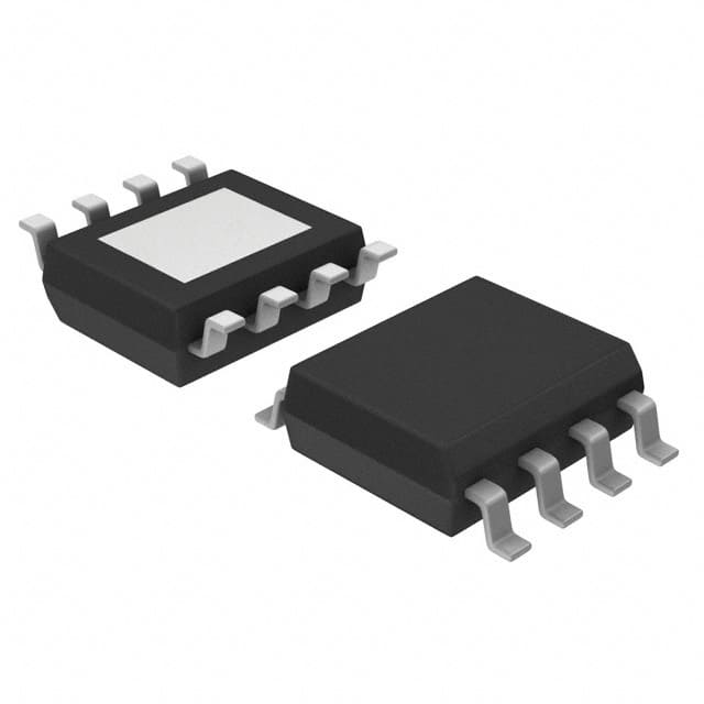
- Part No.:
- A8586KLJTR-T-2
- Manufacturer:
- Allegro MicroSystems
- Package:
- 8-SOIC (0.154", 3.90mm Width) Exposed Pad
- Datasheet:
-
 A8586KLJTR-T-2.pdf
- Description:
- IC REG BUCK ADJ 3.5A 8SOIC
- Quantity:
- Payment:

- Shipping:

Inventory:9,000
Please send an inquiry. Send us your inquiry, and we will respond immediately.
Product details
Overview
A8586KLJTR-T-2 from Allegro MicroSystems is a high-frequency, current-mode synchronous step-down DC/DC regulator with integrated 150 mΩ high-side MOSFET, delivering up to 3.5 A output current, adjustable 0.8–30 V output voltage, and programmable switching frequency up to 4 MHz - designed for automotive power conversion in 12 V/24 V battery systems.
For engineers reviewing the A8586KLJTR-T-2 datasheet, A8586KLJTR-T-2 pinout, A8586KLJTR-T-2 application, or A8586KLJTR-T-2 equivalent, key selection considerations include its AEC-Q100 qualification, PFM-disabled operation (A8586-2 variant), dither-enabled EMI reduction, 30 µA quiescent current, and SOIC-8 (LJ) thermal-pad package compatibility with industrial and automotive PCB layouts.
Technical Context
The A8586KLJTR-T-2 implements fixed-frequency PWM control with internal slope compensation enabling stable operation at duty cycles >50%, supports pre-biased startup, and features cycle-by-cycle overcurrent protection with hiccup-mode recovery. Its transconductance error amplifier (60 µA/V typ.) interfaces with external RC compensation on the COMP pin for loop stability across wide input/output conditions.
It integrates a 2.9 V internal LDO powered from VIN, bootstrap gate driver with BST-SW UVLO (1.8 V), and dual-stage soft-start (quarter-then-half-then-full frequency ramp). Frequency dithering (±8% around fSW, 12 kHz triangle modulation) is active per A8586-2 specification, reducing peak EMI emissions without requiring external components.
Key Specifications
| Parameter | Value and Actual Design Meaning |
|---|---|
| Input Voltage Range | 3.8 V to 36 V - supports direct connection to automotive battery rails including cold-crank (6 V) and load-dump (36 V) transients. |
| Output Current | Up to 3.5 A continuous - enabled by 150 mΩ RDS(on) MOSFET and SOIC-8 thermal pad (RθJA = 35 °C/W). |
| Switching Frequency | Programmable 0.2–4 MHz via RFREQ resistor - allows EMI band avoidance (e.g., AM radio, ADSL) and optimization of size vs. efficiency. |
| Quiescent Current | 30 µA typical - enables ultra-low-power standby in always-on automotive modules (e.g., telematics, body control units). |
| Feedback Reference | 0.792 V ±1.6% - sets output voltage accuracy; used with external resistor divider (e.g., RFB2 = 40.2 kΩ) for precise 3.3 V or 5 V regulation. |
| Protection Features | Pulse-by-pulse OCP, hiccup-mode short-circuit, BOOT open/short detection, VIN UVLO (3.0 V start), thermal shutdown (170 °C), and freewheel diode fault sensing. |
| EMI Mitigation | Frequency dithering (±8%), controlled switch-node slew rates, and soft freewheel diode turn-off - reduces conducted/radiated emissions without added filtering. |
Pinout & Package
Package: 8-pin SOIC with exposed thermal pad (suffix LJ), RoHS-compliant, JEDEC-standard footprint. Thermal pad must be soldered to PCB ground plane for optimal thermal performance (RθJA = 35 °C/W).
| Pin/Terminal | Circuit Role | Design Meaning |
|---|---|---|
| SW | Switch node | Source of internal high-side MOSFET; connects directly to inductor and freewheel diode cathode - requires minimal trace length and high-current routing. |
| EN | Enable input | High-voltage logic input (rated to 40 V); pulls up internally with 1 µA; enables automatic VIN-based startup when tied to VIN. |
| COMP | Error amplifier output | Connects to external RZCZ compensation network; clamped between 0.75 V and 1.5 V; pulled low during faults. |
| FB | Feedback input | Senses divided output voltage; regulates to 0.792 V reference; supports pre-biased startup and OVP monitoring. |
| GND | Power and signal ground | Common return for control circuitry, power stage, and thermal pad - must be low-impedance connection to minimize noise coupling. |
| FREQ | Frequency setting | Connects to GND via RFREQ resistor (e.g., 45.3 kΩ for 2 MHz); sets oscillator frequency with ±10% tolerance over temperature. |
| VIN | Main power input | Supplies control circuits and MOSFET drain; requires local 10 µF ceramic capacitor; UVLO activates below 3.0 V. |
| BST | Bootstrap supply | Connects to SW via 100 nF ceramic capacitor; generates gate drive voltage >VIN for high-side MOSFET; includes 1.8 V UVLO. |
Key Features
| Feature | Design Value |
|---|---|
| Integrated Power Stage | 150 mΩ high-side N-channel MOSFET eliminates external switch and reduces BOM count and layout area. |
| PFM Disable (A8586-2) | Eliminates light-load frequency modulation - ensures constant switching frequency for predictable EMI and reduced output ripple. |
| Dither-Enabled EMI Reduction | ±8% triangular frequency modulation at 12 kHz sweeps fundamental harmonics, lowering peak radiated emissions by up to 10 dB. |
| Ceramic-Capacitor Stable | No minimum ESR requirement - supports low-profile, high-reliability MLCCs instead of bulkier electrolytics or tantalums. |
| Automotive-Grade Protection | AEC-Q100 Grade 1 (−40°C to +125°C), pin-to-ground short tolerance, BOOT/freewheel diode fault detection, and thermal hysteresis (20°C). |
Applications
| Automotive Body Control Module | Industrial PLC I/O Power |
|---|---|
Use Scenario: Powering microcontrollers, CAN transceivers, and sensor interfaces in door modules, seat controllers, and lighting ECUs. IC Role / Device Role / Timing Role: Primary 5 V/3.3 V buck converter supplying logic rails; operates continuously across battery voltage range (6–16 V) and load-dump events. Use Value: 30 µA quiescent current prevents battery drain during vehicle sleep mode; AEC-Q100 qualification ensures reliability over 15-year automotive lifecycle. |
Use Scenario: Generating isolated 12 V or 24 V auxiliary rails for analog input conditioning, relay drivers, and fieldbus interface ICs in factory automation systems. IC Role / Device Role / Timing Role: High-input-voltage step-down regulator accepting 24–48 V DC industrial bus; delivers stable 12 V @ 2 A with <10 mV ripple. Use Value: Programmable 2–4 MHz switching enables compact magnetics; dithering meets CISPR 22 Class B conducted emission limits without ferrite beads. |
| Telematics Head-End Unit | 12 V Battery-Powered Test Equipment |
Use Scenario: Supplying 3.3 V to LTE modem, GNSS receiver, and secure MCU in connected car gateways operating under stop-start and cold-crank conditions. IC Role / Device Role / Timing Role: Main system power regulator with pre-biased startup and fast transient response (<10 µs) to handle burst data transmission loads. Use Value: 3.8–36 V input range accommodates 12 V battery dips to 6 V and surges to 36 V; hiccup-mode OCP prevents thermal runaway during antenna fault events. |
Use Scenario: Portable handheld test instruments requiring long runtime from single 12 V Li-ion pack while maintaining clean analog supply for ADC references. IC Role / Device Role / Timing Role: Efficient 3.3 V/5 V point-of-load regulator with low-noise output and minimal standby loss. Use Value: Ceramic-capacitor stability and dithering reduce output noise floor; 30 µA IQ extends battery life beyond 100 hours in measurement standby mode. |
Equivalent & Alternatives
The following parts are listed as comparable options for similar buck regulator applications.
| Alternative Part | Technical Difference | Application Difference | Selection Advice |
|---|---|---|---|
| LM61480RQWR | 40 V max input, 8 A output, no integrated BOOT diode; requires external bootstrap diode; no dithering; higher IQ (25 µA typ. but no sleep mode). | Targeted at higher-current industrial supplies; lacks AEC-Q100 rating and automotive fault diagnostics. | Choose LM61480RQWR only if >4 A output or 40 V absolute max input is required; not drop-in due to different pinout and compensation scheme. |
| MPQ4420AGL-A | 36 V max input, 2 A output, 170 mΩ RDS(on), no dithering, no PFM disable option, lower thermal performance (SOIC-8 RθJA ≈ 50 °C/W). | Cost-optimized for non-automotive consumer/industrial use; lacks hiccup-mode short-circuit recovery and BOOT fault detection. | MPQ4420AGL-A may serve as lower-cost alternative where AEC-Q100, EMI compliance, or 3.5 A capability are not required. |
Compared with LM61480RQWR and MPQ4420AGL-A, the A8586KLJTR-T-2 uniquely combines AEC-Q100 qualification, dither-enabled EMI control, PFM disable for deterministic frequency, and robust automotive-grade protection - making it the preferred choice for safety-critical, noise-sensitive, and long-lifecycle embedded power designs.
Availability
A8586KLJTR-T-2 is available at Aetrix Electronics and suitable for automotive body electronics, industrial PLC power supplies, and battery-powered telematics systems requiring stable component supply, long-term lifecycle support, and AEC-Q100-compliant sourcing.
Supply support for A8586KLJTR-T-2 includes scheduled delivery planning, volume procurement assistance, BOM continuity management, traceable sourcing, and lifecycle availability coordination for OEM customers, industrial embedded developers, connected-device designers, and electronics production programs.
Manufacturer
Allegro MicroSystems is a U.S.-based semiconductor company specializing in high-performance power ICs, magnetic sensors, and motor driver solutions for automotive and industrial markets.
The A8586 product line was developed specifically for demanding automotive power conversion applications - emphasizing AEC-Q100 reliability, EMI robustness, and wide-input-voltage operation in harsh electrical environments.
FAQ
What is the key functional difference between A8586KLJTR-T-2 and the base A8586 part?
The A8586KLJTR-T-2 is the A8586-2 variant, meaning it disables pulse-frequency modulation (PFM) while retaining frequency dithering. This ensures constant switching frequency across all load conditions - critical for EMI predictability and minimizing output voltage ripple in noise-sensitive applications. The base A8586 enables PFM at light loads to improve efficiency, whereas A8586KLJTR-T-2 prioritizes spectral consistency and low-ripple performance.
Does A8586KLJTR-T-2 require an external freewheeling diode?
Yes, A8586KLJTR-T-2 requires an external Schottky freewheeling diode connected between SW and GND. Although the IC integrates a high-side MOSFET, it does not include a synchronous rectifier; the diode provides the return path for inductor current during high-side switch off-time. The device monitors diode health and enters hiccup mode if the diode is open or shorted - confirming its functional necessity in the power stage.
What is the recommended layout practice for the BST capacitor on A8586KLJTR-T-2?
For A8586KLJTR-T-2, a 100 nF X7R ceramic capacitor must be placed directly between BST and SW pins with minimal trace length (<2 mm) and no series resistance. This ensures reliable bootstrap charging during each switching cycle. The capacitor must be rated for ≥16 V and located adjacent to the IC to avoid voltage droop or ringing that could cause high-side MOSFET turn-off failure or BOOT fault triggering.
Can A8586KLJTR-T-2 operate with a 5 V input supply?
No - A8586KLJTR-T-2 has a minimum input voltage of 3.8 V, but its internal LDO requires VIN > 3.0 V to regulate, and UVLO releases at ~3.0 V. However, stable operation at 5 V is fully supported: the device maintains regulation down to 0.8 V output, delivers full 3.5 A current, and retains all protections including thermal shutdown and overcurrent limiting. Input capacitance must still meet datasheet recommendations (≥10 µF ceramic).
How does the soft-start function behave during pre-biased output conditions in A8586KLJTR-T-2?
In A8586KLJTR-T-2, pre-biased startup is handled by holding COMP low and tri-stating SW until the internal soft-start voltage ramps above the existing FB voltage. This prevents reverse current flow into the output capacitors and avoids discharging the pre-charged rail. Once soft-start crosses VFB, normal PWM regulation resumes - ensuring safe, controlled ramp-up without output overshoot or inrush stress on downstream circuitry.
A8586KLJTR-T-2 Specifications
- Product attributes
- Attribute value
- Manufacturer:
- Allegro MicroSystems
- Series:
- -
- Package/Case:
- 8-SOIC (0.154", 3.90mm Width) Exposed Pad
- Packaging:
- Tape & Reel (TR)
- Product Status:
- Active
- Function:
- Step-Down
- Output Configuration:
- Positive
- Topology:
- Buck
- Output Type:
- Adjustable
- Number of Outputs:
- 1
- Voltage - Input (Min):
- 3.8V
- Voltage - Input (Max):
- 36V
- Voltage - Output (Min/Fixed):
- 0.8V
- Voltage - Output (Max):
- 30V
- Current - Output:
- 3.5A
- Frequency - Switching:
- 200kHz ~ 4MHz
- Synchronous Rectifier:
- No
- Operating Temperature:
- -40°C ~ 150°C (TJ)
- Grade:
- Automotive
- Qualification:
- AEC-Q100
- Mounting Type:
- Surface Mount
- Supplier Device Package:
- 8-SOIC-EP
A8586KLJTR-T-2 FAQ
1.How can I place an order for A8586KLJTR-T-2 through Aetrix?
Please submit a Request for Quotation (RFQ) for A8586KLJTR-T-2 on Aetrix. Our sales agent will provide a competitive quotation and guide you through the order confirmation once you accept the terms.
2.Are the price and stock information for A8586KLJTR-T-2 reliable?
The price and inventory of A8586KLJTR-T-2 are updated periodically and may fluctuate due to market conditions. Stock and pricing data are typically refreshed every 24 hours. Quotation validity for A8586KLJTR-T-2 is usually 5 days.
3.What payment methods are accepted for A8586KLJTR-T-2?
We accept Wire Transfer, PayPal, Credit Card, Western Union, MoneyGram, and Escrow for A8586KLJTR-T-2 transactions.
Note: Certain payment methods may incur a processing fee.
4.How is shipping managed for A8586KLJTR-T-2?
A8586KLJTR-T-2 orders can be shipped via leading logistics carriers, including DHL, UPS, FedEx, TNT, or Registered Mail.
Once your A8586KLJTR-T-2 order is processed, you will receive an email with the shipment details and tracking number.
Note: Tracking information may take up to 24 hours to appear. Express delivery typically takes 3–5 business days.
5.How can I obtain technical support or documentation for A8586KLJTR-T-2?
For technical support, including A8586KLJTR-T-2 datasheets, pinout diagrams, or application guidance, please contact our engineering support team. They can provide detailed documentation and assistance for your A8586KLJTR-T-2 requirements.
6.How does Aetrix verify that A8586KLJTR-T-2 is sourced from the original manufacturer or authorized distributors?
All A8586KLJTR-T-2 products on Aetrix are procured from qualified distributors and authorized channels. Our dedicated quality assurance team conducts strict verification, including traceability checks and, if necessary, third-party testing. This ensures that A8586KLJTR-T-2 meets industry standards.
7.What is the process for return or replacement of A8586KLJTR-T-2?
All A8586KLJTR-T-2 units undergo pre-shipment inspection (PSI). If there is an issue with A8586KLJTR-T-2, returns or replacements are accepted under the following conditions:
1.Quantity discrepancies, incorrect items, or visible external defects (such as breakage or corrosion), acknowledged by Aetrix.
2.The issue is reported within 90 days of delivery.
3.The A8586KLJTR-T-2 part is unused and in its original packaging.
Return procedure for A8586KLJTR-T-2:
1.Submit a request within 90 days.
2.Obtain a Return Material Authorization (RMA) from Aetrix.
A8586KLJTR-T-2 Tags
-
TPS562201DDCR
Texas Instruments

-
MC34063ABD-TR
STMicroelectronics
-
TPS561201DDCR
Texas Instruments

-
MC33063ADR
Texas Instruments
-
MC34063ADR
Texas Instruments

-
TPS560200DBVR
Texas Instruments
-
AP3012KTR-G1
Diodes Incorporated
-
TLV61048DBVR
Texas Instruments
-
AZ34063UMTR-G1
Diodes Incorporated
-
TPS562200DDCR
Texas Instruments
-
AP62300TWU-7
Diodes Incorporated
-
MC34063EBD-TR
STMicroelectronics
Tech Hub

A practical engineering and sourcing framework covering lifecycle verification, lifetime-buy calculations, replacement qualification, supplier checks and counterfeit-risk controls.

TTL and CMOS logic families differ in thresholds, loading, output drive, power and timing. This engineering guide compares 74HC and 74HCT, calculates noise margins and checks 3.3 V/5 V compatibility.

A practical engineering guide to 3.3V and 5V logic compatibility, input thresholds, resistor dividers, translator ICs, MOSFET level shifting, I2C pull-ups, timing limits and power-sequencing risks.

The 74HC595 uses push-pull logic outputs, while the TPIC6B595 uses 50 V open-drain DMOS sinks for higher-power loads. This guide compares timing, current limits, 3.3 V interfacing, load wiring, thermal…

The 74HC595 converts serial data into eight stable parallel outputs. This guide covers pin functions, shift and storage timing, OE and MR behavior, drive-current limits, cascading, voltage compatibilit…

A technical comparison of level-sensitive latches and edge-triggered flip-flops, covering timing windows, setup and hold limits, master–slave operation, time borrowing, race-through, HDL inference and…

A D latch stores one bit while Enable controls when data can pass. This reference covers gate-level operation, truth tables, transparency, setup and hold timing, LE versus OE, common ICs and practical …

An SR latch stores one bit through cross-coupled feedback. This engineering reference covers NOR and NAND implementations, truth tables, forbidden-state recovery, gated operation, switch debouncing, fa…

Latch circuits retain one bit through feedback. This technical reference covers SR and D latches, truth tables, transparency, timing limits, latch-versus-flip-flop behavior, applications and common log…

An engineering guide to LED driver operation, constant-current and constant-voltage outputs, linear and switching topologies, dimming, IC selection, calculations, replacement compatibility, and fault c…


