
 My Inquiry
 My Account


Allegro MicroSystems A8660KESTR-J
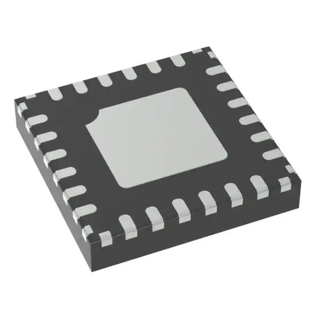
- Part No.:
- A8660KESTR-J
- Manufacturer:
- Allegro MicroSystems
- Category:
- Power Supply Controllers, Monitors
- Package:
- 20-WFQFN Exposed Pad
- Datasheet:
-
 A8660KESTR-J.pdf
- Description:
- SYNCHRONOUS BUCK CONTROLLER
- Quantity:
- Payment:

- Shipping:

Inventory:4,083
Please send an inquiry. Send us your inquiry, and we will respond immediately.
Product details
Overview
A8660KESTR-J from Allegro MicroSystems is a wide-input synchronous buck controller for automotive and industrial DC/DC conversion, featuring 3.0–45 V input range, adjustable 0.8–20 V output, 200 kHz–2.2 MHz programmable switching frequency, PWM frequency dithering (±10%), and integrated high-current gate drivers (HD/LD) with non-overlap logic. It delivers robust power control in infotainment systems and ADAS modules.
For engineers reviewing the A8660KESTR-J datasheet, A8660KESTR-J pinout, A8660KESTR-J application, or A8660KESTR-J equivalent, key selection considerations include its AEC-Q100 qualification, NPOR open-drain power-good output with adjustable delay, soft recovery from dropout, external compensation network support, and SYNCIN synchronization capability for AM-band interference avoidance.
Technical Context
The A8660KESTR-J implements peak current-mode control with internal slope compensation (16 mV), enabling stable operation up to 95% duty cycle across wide VIN/VOUT ratios and frequencies. Its error amplifier features dual-input "analog OR" logic between soft-start and regulation paths, with transconductance of 550–950 µA/V depending on FB voltage.
It integrates dual gate drivers: HD delivers ±0.8/±1.5 A (source/sink) referenced to BOOT–LX, LD delivers ±2.0/±1.8 A referenced to VREG–GND; both employ adaptive dead-time control (10–30 ns non-overlap). Protection includes pulse-by-pulse current limit (70 mV HS threshold), hiccup-mode short-circuit response (120-cycle counter), and thermal shutdown at 155–170°C.
Key Specifications
| Parameter | Value and Actual Design Meaning |
|---|---|
| Input Voltage Range | 3.0 V to 45 V - supports direct battery connection in 12 V/24 V automotive systems without pre-regulation. |
| Output Voltage Range | 0.8 V to 20 V - set via external resistor divider on FB pin; 800 mV ±1% reference enables precise low-voltage rail generation. |
| Switching Frequency | 200 kHz to 2.2 MHz - programmed via FSET pin resistor; allows optimization of size (high-freq) vs. efficiency (low-freq). |
| PWM Dithering | ±10% frequency spread at 12 kHz modulation - reduces EMI peak amplitude without altering average fOSC or requiring additional filtering. |
| Gate Drive Capability | HD: 0.8 A source / 1.5 A sink; LD: 2.0 A source / 1.8 A sink - drives large N-channel MOSFETs directly, minimizing external driver needs. |
| NPOR Output | Open-drain power-good signal with programmable rising delay via CPOR capacitor - enables sequenced power-up and fault-aware system reset. |
| Protection Features | VIN UVLO (3.4 V start), VOUT OVP (880 mV), thermal shutdown (170°C), hiccup-mode SC, BOOT open/short detection - ensures fail-safe operation in harsh environments. |
Pinout & Package
Package: 20-pin QFN (4 × 4 mm, ES variant) with exposed thermal pad and wettable flank - optimized for automotive PCB assembly and thermal dissipation (RθJA = 37°C/W, RθJC = 2°C/W).
| Pin/Terminal | Circuit Role | Design Meaning |
|---|---|---|
| 1 NPOR | Open-drain power-good output | Asserts low when FB voltage deviates >±2%; delay programmable via CPOR capacitor for controlled sequencing. |
| 3 FSET | Oscillator frequency programming | Resistor-to-ground sets base fOSC from 200 kHz to 2.2 MHz; enables precise EMI tuning and layout optimization. |
| 5 COMP | Error amplifier output | Drives external RZ/CZ/CP compensation network to stabilize loop across load/transient conditions. |
| 6 FB | Feedback input | Connects to resistor divider from VOUT; senses regulated output with 800 mV ±1% reference accuracy at 150°C. |
| 7 CS– / 8 CS+ | Differential current sense inputs | Monitor RSEN voltage drop; enable pulse-by-pulse current limiting and hiccup-mode fault detection. |
| 9 SYNC | External synchronization input | Accepts clock signal (1.2–1.5× fOSC) to shift harmonics away from AM band (<520 kHz designs). |
| 14 HD / 11 LD | High-side / low-side gate drivers | Drive external N-MOSFETs; HD referenced to BOOT–LX, LD referenced to VREG–GND; non-overlap prevents shoot-through. |
| 15 BOOT | High-side bootstrap supply | Charged by internal LDO during LX low phase; requires ceramic capacitor to LX for gate drive integrity. |
| 17 SS | Soft-start timing | Capacitor defines ramp time for monotonic VOUT rise, inrush control, and dropout recovery behavior. |
| 18 ENBAT / 19 EN | Ignition-key / logic enable inputs | ENBAT rated to 50 V for direct battery-switch interface; EN accepts 1.6 V logic-high for microcontroller control. |
Key Features
| Feature | Design Value |
|---|---|
| Automotive AEC-Q100 qualified | Rated for –40°C to +150°C junction temperature - validated for under-hood and instrument cluster deployment. |
| Soft recovery from dropout | Prevents VOUT overshoot during rapid VIN recovery (e.g., cold-crank to nominal battery) - avoids load damage and OV protection activation. |
| External compensation network | COMP pin supports full RZ/CZ/CP tuning - enables stability optimization across wide fOSC range and varying output capacitance. |
| Pre-bias startup | Allows monotonic VOUT ramp even when output capacitor is pre-charged - eliminates output reversal and system reset events. |
| Robust FMEA coverage | Detects pin opens/shorts, BOOT faults, LX shorts-to-GND/VIN, and component-level failures - meets ASIL-B functional safety readiness. |
Applications
| Infotainment Systems | ADAS Camera Modules |
|---|---|
|
Use Scenario: Powering SoC, display drivers, and audio codecs in head units with wide battery voltage swings (5–16 V) and strict EMI limits. IC Role / Device Role / Timing Role: Synchronous buck controller regulating 1.1 V core and 3.3 V I/O rails with dithered PWM to meet CISPR-25 Class 5 conducted emissions. Use Value: Eliminates need for external EMI filters due to ±10% frequency dithering, reducing BOM cost and board area while maintaining AEC-Q100 compliance. |
Use Scenario: Supplying image sensor and ISP in forward-facing camera with fast transient response and thermal resilience. IC Role / Device Role / Timing Role: High-current buck controller delivering 5 V @ 10 A with soft recovery to prevent VOUT overshoot during engine cranking dips. Use Value: Ensures uninterrupted imaging during 5 V battery sag to 6 V - avoids frame loss or sensor reset thanks to controlled recovery and pre-bias startup. |
| Instrument Clusters | Industrial HMIs |
|
Use Scenario: Generating 3.3 V and 5 V rails for TFT LCD, microcontroller, and CAN transceivers in digital dashboards. IC Role / Device Role / Timing Role: Dual-rail controller with NPOR sequencing and ENBAT ignition control - enables safe power-up/down synchronized with vehicle key state. Use Value: NPOR delay (programmable via CPOR) coordinates MCU boot with stable VOUT, preventing brown-out resets during cold-start sequences. |
Use Scenario: Providing isolated 12 V and 5 V supplies in factory-floor HMIs exposed to 45 V surges and ambient temperatures up to 85°C. IC Role / Device Role / Timing Role: Wide-VIN buck controller with 45 V absolute max rating and thermal shutdown at 170°C - sustains operation during line transients. Use Value: Withstands ISO 7637-2 Pulse 5a (75 V/350 ms) without latch-off, thanks to VIN UVLO hysteresis (800 mV) and robust overvoltage protection. |
Equivalent & Alternatives
The following parts are listed as comparable options for similar synchronous buck controller applications.
| Alternative Part | Technical Difference | Application Difference | Selection Advice |
|---|---|---|---|
| MPQ4333-AEC1 | Fixed 2.2 MHz fSW; no frequency dithering or SYNCIN; integrated MOSFETs (12 A); smaller 3 × 4 mm QFN. | Limited to mid-power applications (<12 A); lacks AM-band synchronization and programmable soft-start delay. | Choose for space-constrained, lower-current designs where EMI filtering is handled externally and VIN < 36 V. |
| LM5143A-Q1 | Two-phase controller; supports up to 60 V VIN; includes PMBus interface; no NPOR output; fixed 100 µs soft-start. | Targeted at high-power (>20 A), multi-phase systems; requires external DAC for VOUT adjustment; no dithering. | Choose when scaling beyond 15 A or requiring digital telemetry; avoid if NPOR sequencing or EMI-sensitive single-rail design is required. |
Compared with MPQ4333-AEC1 and LM5143A-Q1, the A8660KESTR-J uniquely combines AEC-Q100 qualification, ±10% PWM dithering, SYNCIN synchronization, and programmable NPOR delay - making it optimal for EMI-critical, single-phase automotive rails requiring precise power sequencing and robust dropout recovery.
Availability
A8660KESTR-J is available at Aetrix Electronics and suitable for automotive infotainment systems, ADAS camera modules, and industrial human-machine interfaces requiring stable component supply, long-term lifecycle support, and AEC-Q100-compliant performance.
Supply support for A8660KESTR-J includes scheduled delivery planning, volume procurement assistance, BOM continuity management, traceable sourcing, and lifecycle availability coordination for OEM customers, industrial embedded developers, connected-device designers, and electronics production programs.
Manufacturer
Allegro MicroSystems is a U.S.-based semiconductor company specializing in high-performance power ICs and magnetic sensors for automotive and industrial markets.
The A8660KESTR-J belongs to Allegro's automotive-grade synchronous buck controller product line, designed specifically for demanding DC/DC conversion in engine compartments, instrument clusters, and ADAS subsystems where reliability, EMI control, and wide input range are critical.
FAQ
What is the maximum input voltage rating for the A8660KESTR-J?
The A8660KESTR-J has an absolute maximum input voltage (VIN) rating of 50 V, with continuous operation specified from 3.0 V to 45 V. This wide range supports direct connection to 12 V and 24 V automotive batteries, including load-dump transients up to 45 V, and enables use in industrial 36 V systems without external clamping.
Does the A8660KESTR-J support synchronization to an external clock?
Yes, the A8660KESTR-J supports external synchronization via the SYNC pin. When an external clock is applied, it locks the internal PWM frequency to 1.2×–1.5× the base fOSC, enabling harmonic shifting to avoid AM-band interference in low-frequency designs (<520 kHz). PWM dithering is automatically disabled during synchronization.
How is the output voltage set on the A8660KESTR-J?
The output voltage of the A8660KESTR-J is set using an external resistor divider connected between VOUT, FB, and AGND. The internal 800 mV reference (±1% at 150°C) determines VOUT = 0.8 V × (1 + RFB1/RFB2). For example, RFB1 = 16.5 kΩ and RFB2 = 5.23 kΩ yields 3.3 V output, as shown in the typical application schematic.
What protection features does the A8660KESTR-J include?
The A8660KESTR-J includes pulse-by-pulse current limiting, hiccup-mode short-circuit protection, BOOT open/short detection, VIN undervoltage lockout (3.4 V start), VOUT overvoltage protection (880 mV), thermal shutdown (170°C), and robust FMEA coverage for pin faults. These ensure fail-safe operation in automotive environments subject to voltage transients and thermal stress.
Is the A8660KESTR-J pin-compatible with other Allegro buck controllers?
No, the A8660KESTR-J is not pin-compatible with earlier Allegro controllers such as the A8661 or A8662. Its 20-pin QFN (ES) package, pin assignments (e.g., dedicated ENBAT, ENBATS, CPOR), and internal architecture are unique. Migration requires PCB layout revision and compensation network re-optimization due to differences in gate drive structure and error amplifier behavior.
A8660KESTR-J Specifications
- Product attributes
- Attribute value
- Manufacturer:
- Allegro MicroSystems
- Series:
- -
- Package/Case:
- 20-WFQFN Exposed Pad
- Packaging:
- Tape & Reel (TR)
- Product Status:
- Active
- Programmable:
- Not Verified
- Applications:
- Consumer, Industrial
- Voltage - Input:
- 3V ~ 45V
- Voltage - Supply:
- -
- Current - Supply:
- 2.5 mA
- Operating Temperature:
- -40°C ~ 150°C (TJ)
- Grade:
- Automotive
- Qualification:
- AEC-Q100
- Mounting Type:
- Surface Mount, Wettable Flank
- Supplier Device Package:
- 20-QFN (4x4)
A8660KESTR-J FAQ
1.How can I place an order for A8660KESTR-J through Aetrix?
Please submit a Request for Quotation (RFQ) for A8660KESTR-J on Aetrix. Our sales agent will provide a competitive quotation and guide you through the order confirmation once you accept the terms.
2.Are the price and stock information for A8660KESTR-J reliable?
The price and inventory of A8660KESTR-J are updated periodically and may fluctuate due to market conditions. Stock and pricing data are typically refreshed every 24 hours. Quotation validity for A8660KESTR-J is usually 5 days.
3.What payment methods are accepted for A8660KESTR-J?
We accept Wire Transfer, PayPal, Credit Card, Western Union, MoneyGram, and Escrow for A8660KESTR-J transactions.
Note: Certain payment methods may incur a processing fee.
4.How is shipping managed for A8660KESTR-J?
A8660KESTR-J orders can be shipped via leading logistics carriers, including DHL, UPS, FedEx, TNT, or Registered Mail.
Once your A8660KESTR-J order is processed, you will receive an email with the shipment details and tracking number.
Note: Tracking information may take up to 24 hours to appear. Express delivery typically takes 3–5 business days.
5.How can I obtain technical support or documentation for A8660KESTR-J?
For technical support, including A8660KESTR-J datasheets, pinout diagrams, or application guidance, please contact our engineering support team. They can provide detailed documentation and assistance for your A8660KESTR-J requirements.
6.How does Aetrix verify that A8660KESTR-J is sourced from the original manufacturer or authorized distributors?
All A8660KESTR-J products on Aetrix are procured from qualified distributors and authorized channels. Our dedicated quality assurance team conducts strict verification, including traceability checks and, if necessary, third-party testing. This ensures that A8660KESTR-J meets industry standards.
7.What is the process for return or replacement of A8660KESTR-J?
All A8660KESTR-J units undergo pre-shipment inspection (PSI). If there is an issue with A8660KESTR-J, returns or replacements are accepted under the following conditions:
1.Quantity discrepancies, incorrect items, or visible external defects (such as breakage or corrosion), acknowledged by Aetrix.
2.The issue is reported within 90 days of delivery.
3.The A8660KESTR-J part is unused and in its original packaging.
Return procedure for A8660KESTR-J:
1.Submit a request within 90 days.
2.Obtain a Return Material Authorization (RMA) from Aetrix.
A8660KESTR-J Tags

-
UC3845AD8TR
Texas Instruments
-
UC2843AD8TR
Texas Instruments

-
LM3880MFX-1AE/NOPB
Texas Instruments
-
LM3880MFX-1AA/NOPB
Texas Instruments

-
INA234AIYBJR
Texas Instruments

-
INA700AYWFR
Texas Instruments
-
LM3880MF-1AE/NOPB
Texas Instruments
-
LM3880MF-1AA/NOPB
Texas Instruments

-
LM3881MM/NOPB
Texas Instruments
-
UCC2802DTR
Texas Instruments

-
NCP4305DMTTWG
onsemi

-
INA237AIDGSR
Texas Instruments
Tech Hub

A practical engineering and sourcing framework covering lifecycle verification, lifetime-buy calculations, replacement qualification, supplier checks and counterfeit-risk controls.

TTL and CMOS logic families differ in thresholds, loading, output drive, power and timing. This engineering guide compares 74HC and 74HCT, calculates noise margins and checks 3.3 V/5 V compatibility.

A practical engineering guide to 3.3V and 5V logic compatibility, input thresholds, resistor dividers, translator ICs, MOSFET level shifting, I2C pull-ups, timing limits and power-sequencing risks.

The 74HC595 uses push-pull logic outputs, while the TPIC6B595 uses 50 V open-drain DMOS sinks for higher-power loads. This guide compares timing, current limits, 3.3 V interfacing, load wiring, thermal…

The 74HC595 converts serial data into eight stable parallel outputs. This guide covers pin functions, shift and storage timing, OE and MR behavior, drive-current limits, cascading, voltage compatibilit…

A technical comparison of level-sensitive latches and edge-triggered flip-flops, covering timing windows, setup and hold limits, master–slave operation, time borrowing, race-through, HDL inference and…

A D latch stores one bit while Enable controls when data can pass. This reference covers gate-level operation, truth tables, transparency, setup and hold timing, LE versus OE, common ICs and practical …

An SR latch stores one bit through cross-coupled feedback. This engineering reference covers NOR and NAND implementations, truth tables, forbidden-state recovery, gated operation, switch debouncing, fa…

Latch circuits retain one bit through feedback. This technical reference covers SR and D latches, truth tables, transparency, timing limits, latch-versus-flip-flop behavior, applications and common log…

An engineering guide to LED driver operation, constant-current and constant-voltage outputs, linear and switching topologies, dimming, IC selection, calculations, replacement compatibility, and fault c…


