
 My Inquiry
 My Account


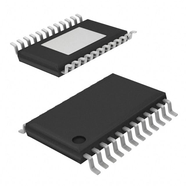
Allegro MicroSystems A8904SLPTR-T
- Part No.:
- A8904SLPTR-T
- Manufacturer:
- Allegro MicroSystems
- Category:
- Motor Drivers, Controllers
- Package:
- 28-TSSOP (0.173", 4.40mm Width) Exposed Pad
- Datasheet:
-
 A8904SLPTR-T.pdf
- Description:
- IC MOTOR DRVR 4.5V-5.5V 28TSSOP
- Quantity:
- Payment:

- Shipping:

Inventory:2,253
Please send an inquiry. Send us your inquiry, and we will respond immediately.
Product details
Overview
A8904SLPTR-T from Allegro MicroSystems is a 3-phase brushless DC motor controller/driver with integrated back-EMF sensing, linear current-mode speed regulation, and programmable serial interface. It delivers up to 1.2 A per phase via low-RDS(on) N-channel DMOS half-bridges, supports sensorless commutation, and operates with 4–14 V load supply and 4.5–5.5 V logic supply. It is used in high-speed spindle control for optical drives and precision cooling fans.
For engineers reviewing the A8904SLPTR-T datasheet, A8904SLPTR-T pinout, A8904SLPTR-T application, or A8904SLPTR-T equivalent, key selection criteria include its 28-pin TSSOP-LP package with exposed thermal pad, programmable transconductance gain (250/500 mA/V), FLL-based speed lock, dynamic braking capability, and real-time diagnostic data output via serial port multiplexer.
Technical Context
The A8904SLPTR-T implements adaptive commutation using dual delay capacitors (CD1/CD2) charged/discharged at controlled rates to synchronize switching with back-EMF zero crossings. Its frequency-locked loop (FLL) compares internally generated TACH (from FCOM transitions) or external sector pulses against a programmable REF counter to produce an analog error signal.
This error directly controls the FILTER terminal voltage, which-via transconductance stage (gm = 250 or 500 mA/V)-linearly regulates low-side MOSFET current. Start-up uses a dedicated CST oscillator and watchdog timing (CWD) to blank comparators during transients and force commutation until valid back-EMF is detected.
Key Specifications
| Parameter | Value and Actual Design Meaning |
|---|---|
| Output Current | ±1.2 A continuous per phase; enables direct drive of mid-power BLDC motors without external gate drivers |
| Load Supply Range | 4.0–14 V; compatible with 5 V and 12 V motor rails in optical storage and fan applications |
| Transconductance Gain | Selectable 250 mA/V or 500 mA/V; sets current-to-voltage conversion slope for precise linear current control |
| FLL Oscillator Max | 20 MHz; supports high-resolution speed reference generation for sub-1% speed regulation accuracy |
| Thermal Resistance | RθJA = 28 °C/W (4-layer PCB); enables sustained 1.2 A operation at 85 °C ambient with minimal heatsinking |
| Serial Port Speed | Up to 3.3 MHz clock; allows full 29-bit configuration within <10 μs for rapid mode switching |
| Brake Peak Current | ±3.0 A transient; provides strong dynamic braking by shorting all windings to ground via serial or BRAKE pin |
Pinout & Package
The A8904SLPTR-T is housed in a 28-pin thin-profile TSSOP (Package LP) with 0.65 mm pitch and an exposed thermal pad on the underside for enhanced heat dissipation. The package height is <1.2 mm, suitable for space-constrained optical drive assemblies.
| Pin/Terminal | Circuit Role | Design Meaning |
|---|---|---|
| 1 (ANALOG GROUND) | Analog reference return | Must be connected to power ground externally; separates analog noise from digital switching paths |
| 2 (FILTER) | Speed control integrator node | Voltage here sets motor current via transconductance stage; external RC filter shapes closed-loop response |
| 3 (SECTOR DATA) | External tachometer input | Accepts index/sector pulses for high-precision speed lock when internal back-EMF sensing is insufficient |
| 4 (LOGIC SUPPLY) | Digital core power rail | 5 V ±5%; powers serial interface, logic, and internal regulators; UVLO triggers at 3.6 V |
| 5 (OSCILLATOR) | Reference clock input | Drives internal speed reference counter; supports crystal or external clock up to 20 MHz |
| 6 (DATA OUT) | Multiplexed diagnostic output | Configurable via D22/D23 to output TACH, FCOM, SYNC, or thermal shutdown flag in real time |
| 15 (LOAD SUPPLY) | Motor power rail | 4–14 V input; powers DMOS half-bridges and charge pump; internal clamp diodes handle flyback energy |
| 20 (OUTA), 24 (OUTB), 25 (OUTC) | Half-bridge outputs | Drive motor phases A/B/C; each integrates N-channel source/sink DMOS with rDS(on) ≤1.4 Ω total |
| 26 (CENTERTAP) | Back-EMF reference node | Connects to motor star point; used as common-mode reference for differential back-EMF zero-crossing detection |
| 27 (BRAKE) | Dynamic brake enable | Active-low; initiates simultaneous sinking on all three outputs to short windings and dissipate kinetic energy |
| 28 (CRES) | Charge pump reservoir | External capacitor supplies boosted gate drive for high-side DMOS; critical for full 12 V motor operation |
Key Features
| Feature | Design Value |
|---|---|
| Sensorless back-EMF commutation | Eliminates Hall sensors or encoders; uses adaptive CD1/CD2 delay timing synchronized to FCOM zero crossings |
| Programmable transconductance gain | 250 mA/V or 500 mA/V selection via D28 bit; optimizes current resolution vs. bandwidth trade-off per motor winding resistance |
| Real-time diagnostic multiplexing | DATA OUT pin outputs TACH, FCOM, SYNC, or thermal fault without additional pins-reduces system BOM count |
| YANK speed-loop initialization | Pulls FILTER to threshold voltage at startup, forcing max current limit until first ERROR FAST signal-ensures reliable spin-up under load |
| Watchdog-enabled start-up recovery | If no valid back-EMF detected during blanking window, forces commutation until synchronization is achieved-prevents stall in moving-spindle scenarios |
Applications
| Optical Disk Drive Spindle Control | High-Speed Cooling Fan Regulation |
|---|---|
Use Scenario: Precise constant-angular-velocity (CAV) rotation of Blu-ray or DVD spindles across varying disc mass and friction loads. IC Role / Device Role / Timing Role: Primary motor controller executing sensorless commutation, FLL-based speed lock, and real-time current limiting. Use Value: Achieves <±0.5% speed stability over temperature and voltage variation using internal back-EMF sensing and programmable 14-bit REF counter. | Use Scenario: Low-noise, variable-speed airflow control in server chassis and telecom equipment requiring EMI-sensitive operation. IC Role / Device Role / Timing Role: Linear current-mode driver delivering smooth torque without PWM-induced acoustic noise. Use Value: Eliminates audible whine via analog current regulation-no switching artifacts-while maintaining 10:1 speed range via serial-programmed FLL setpoint. |
| Industrial Pump Motor Control | Medical Imaging Equipment Fans |
Use Scenario: Closed-loop flow-rate control in compact centrifugal pumps where motor inertia and fluid load vary dynamically. IC Role / Device Role / Timing Role: Sensorless BLDC controller with dynamic braking (BRAKE pin) and programmable overcurrent protection for surge suppression. Use Value: Enables instant stop-and-hold via 3.0 A peak brake current, preventing fluid backflow; current limit scaled per gm setting avoids false trips during startup surges. | Use Scenario: Ultra-reliable, low-vibration cooling in MRI and CT scanner gantries where electromagnetic interference must be minimized. IC Role / Device Role / Timing Role: Fault-tolerant motor driver with thermal shutdown reporting (DATA OUT), undervoltage lockout, and real-time FCOM monitoring. Use Value: Thermal fault flag on DATA OUT allows immediate system-level response before junction exceeds 150 °C; analog speed control avoids RF emissions from PWM switching. |
Equivalent & Alternatives
The following parts are listed as comparable options for similar 3-phase BLDC controller applications.
| Alternative Part | Technical Difference | Application Difference | Selection Advice |
|---|---|---|---|
| A8904SLBTR-T | Same die, 24-pin SOICW package with 4 fused leads; RθJA = 35 °C/W (4-layer PCB) | Better suited for through-hole assembly or higher-power derating with heatsink attachment | Select when board space permits larger footprint and thermal management favors SOIC mounting |
| DRV10983ZRTVT | Texas Instruments part; integrated gate drivers + current sense; no external CRES required; fixed 500 mA/V gain | Lacks programmable FLL, sector-data input, and real-time diagnostic multiplexing | Choose for cost-sensitive, lower-complexity fan control where external tach feedback and advanced diagnostics are unnecessary |
Compared with A8904SLBTR-T, the A8904SLPTR-T offers lower thermal resistance (28 vs. 35 °C/W) and thinner profile for slim optical modules; compared with DRV10983ZRTVT, it provides superior speed-lock flexibility (programmable REF counter + external sector input) and richer diagnostics (multiplexed DATA OUT), at the cost of requiring external CRES and tuning capacitors.
Availability
A8904SLPTR-T is available at Aetrix Electronics and suitable for optical drive spindle control, high-speed cooling fan regulation, and industrial pump motor applications requiring stable component supply, long-lifecycle support, and consistent parametric performance across production batches.
Supply support for A8904SLPTR-T includes scheduled delivery planning, volume procurement assistance, BOM continuity management, traceable sourcing, and lifecycle availability coordination for OEM customers, industrial embedded developers, connected-device designers, and electronics production programs.
Manufacturer
Allegro MicroSystems is a U.S.-based designer of high-performance magnetic sensing and power IC solutions, founded in 1989 and headquartered in Worcester, Massachusetts.
The A8904 product line was developed specifically for sensorless 3-phase BLDC motor control in space- and noise-constrained applications such as optical storage, precision cooling, and medical equipment-emphasizing analog-intensive mixed-signal integration in BCD process technology.
FAQ
What is the maximum continuous output current rating of the A8904SLPTR-T?
The A8904SLPTR-T delivers up to ±1.2 A continuous output current per phase under typical operating conditions (TA = 25 °C, 4-layer PCB). This rating assumes proper thermal management via the exposed thermal pad and adherence to the specified RθJA = 28 °C/W. At elevated ambient temperatures or with reduced copper area, the current must be derated per the Absolute Maximum Ratings table to ensure junction temperature remains below 150 °C. The A8904SLPTR-T also supports ±3.0 A peak brake current for dynamic stopping.
How does the A8904SLPTR-T achieve sensorless commutation without Hall sensors?
The A8904SLPTR-T uses back-EMF zero-crossing detection referenced to the motor centertap (CENTERTAP pin). During each commutation state, one phase is left floating (high-impedance), and its induced back-EMF voltage is compared to the centertap voltage. When they cross, the FCOM signal toggles-triggering an adaptive delay circuit (using CD1/CD2 capacitors) that determines optimal commutation timing. This eliminates need for external position sensors while maintaining synchronization across speed ranges. The A8904SLPTR-T also includes watchdog timing (CWD) to force commutation if valid back-EMF is not detected.
Can the A8904SLPTR-T be used with an external tachometer signal instead of internal back-EMF sensing?
Yes-the A8904SLPTR-T supports external speed feedback via the SECTOR DATA pin. When D19 = 1 is programmed via the serial port, the device accepts index or sector pulses (e.g., from an optical encoder disk) to generate the TACH signal. This overrides the internal FCOM-based TACH and allows higher-precision speed lock in applications where back-EMF amplitude drops at low speeds or under heavy load. The FLL still compares this external TACH to the programmable REF counter, preserving closed-loop regulation integrity.
What is the purpose of the CRES pin on the A8904SLPTR-T, and what capacitor value is recommended?
The CRES pin connects to an external reservoir capacitor that supplies boosted gate drive voltage for the high-side DMOS transistors via an internal charge pump. This enables full 12 V motor operation without external high-side drivers. Allegro recommends a 10 μF ceramic capacitor with X7R dielectric and low ESR, placed as close as possible to the CRES and LOAD SUPPLY (VBB) pins. Insufficient CRES capacitance causes high-side gate underdrive, increased rDS(on), and thermal stress-especially at 12 V operation. The A8904SLPTR-T datasheet specifies minimum 4.7 μF for reliable function.
Does the A8904SLPTR-T support dynamic braking, and how is it activated?
Yes-the A8904SLPTR-T supports dynamic braking through two independent methods: (1) asserting the BRAKE pin low, which simultaneously sinks all three outputs (OUTA/OUTB/OUTC) to ground, or (2) setting the brake bit (D29) in the serial port register. Both methods deliver up to ±3.0 A peak current for rapid kinetic energy dissipation. The BRAKE pin includes internal hysteresis and supports external RC timing for controlled brake duration. Braking is fully compatible with ongoing speed regulation-the FLL remains active and resumes control once braking ends.
A8904SLPTR-T Specifications
- Product attributes
- Attribute value
- Manufacturer:
- Allegro MicroSystems
- Series:
- -
- Package/Case:
- 28-TSSOP (0.173", 4.40mm Width) Exposed Pad
- Packaging:
- Tape & Reel (TR)
- Product Status:
- Obsolete
- Motor Type - Stepper:
- -
- Motor Type - AC, DC:
- Brushless DC (BLDC)
- Function:
- Controller - Commutation, Direction Management
- Output Configuration:
- Pre-Driver - Half Bridge (3)
- Interface:
- SPI
- Technology:
- CMOS, DMOS
- Step Resolution:
- -
- Applications:
- General Purpose
- Current - Output:
- -
- Voltage - Supply:
- 4.5V ~ 5.5V
- Voltage - Load:
- 4V ~ 14V
- Operating Temperature:
- -20°C ~ 85°C (TA)
- Grade:
- -
- Qualification:
- -
- Mounting Type:
- Surface Mount
- Supplier Device Package:
- 28-TSSOP-EP
A8904SLPTR-T FAQ
1.How can I place an order for A8904SLPTR-T through Aetrix?
Please submit a Request for Quotation (RFQ) for A8904SLPTR-T on Aetrix. Our sales agent will provide a competitive quotation and guide you through the order confirmation once you accept the terms.
2.Are the price and stock information for A8904SLPTR-T reliable?
The price and inventory of A8904SLPTR-T are updated periodically and may fluctuate due to market conditions. Stock and pricing data are typically refreshed every 24 hours. Quotation validity for A8904SLPTR-T is usually 5 days.
3.What payment methods are accepted for A8904SLPTR-T?
We accept Wire Transfer, PayPal, Credit Card, Western Union, MoneyGram, and Escrow for A8904SLPTR-T transactions.
Note: Certain payment methods may incur a processing fee.
4.How is shipping managed for A8904SLPTR-T?
A8904SLPTR-T orders can be shipped via leading logistics carriers, including DHL, UPS, FedEx, TNT, or Registered Mail.
Once your A8904SLPTR-T order is processed, you will receive an email with the shipment details and tracking number.
Note: Tracking information may take up to 24 hours to appear. Express delivery typically takes 3–5 business days.
5.How can I obtain technical support or documentation for A8904SLPTR-T?
For technical support, including A8904SLPTR-T datasheets, pinout diagrams, or application guidance, please contact our engineering support team. They can provide detailed documentation and assistance for your A8904SLPTR-T requirements.
6.How does Aetrix verify that A8904SLPTR-T is sourced from the original manufacturer or authorized distributors?
All A8904SLPTR-T products on Aetrix are procured from qualified distributors and authorized channels. Our dedicated quality assurance team conducts strict verification, including traceability checks and, if necessary, third-party testing. This ensures that A8904SLPTR-T meets industry standards.
7.What is the process for return or replacement of A8904SLPTR-T?
All A8904SLPTR-T units undergo pre-shipment inspection (PSI). If there is an issue with A8904SLPTR-T, returns or replacements are accepted under the following conditions:
1.Quantity discrepancies, incorrect items, or visible external defects (such as breakage or corrosion), acknowledged by Aetrix.
2.The issue is reported within 90 days of delivery.
3.The A8904SLPTR-T part is unused and in its original packaging.
Return procedure for A8904SLPTR-T:
1.Submit a request within 90 days.
2.Obtain a Return Material Authorization (RMA) from Aetrix.
A8904SLPTR-T Tags

-
DRV2603RUNR
Texas Instruments

-
DRV8837CDSGR
Texas Instruments

-
DRV8837DSGR
Texas Instruments
-
DRV8838DSGR
Texas Instruments

-
DRV8839DSSR
Texas Instruments

-
EMC2301-1-ACZL-TR
Microchip Technology
-
DRV8231ADSGR
Texas Instruments

-
EMC2302-2-AIZL-TR
Microchip Technology

-
DRV8800PWPR
Texas Instruments
-
DRV8835DSSR
Texas Instruments

-
EMC2303-1-KP-TR
Microchip Technology

-
DRV8876PWPR
Texas Instruments
Tech Hub

A practical engineering and sourcing framework covering lifecycle verification, lifetime-buy calculations, replacement qualification, supplier checks and counterfeit-risk controls.

TTL and CMOS logic families differ in thresholds, loading, output drive, power and timing. This engineering guide compares 74HC and 74HCT, calculates noise margins and checks 3.3 V/5 V compatibility.

A practical engineering guide to 3.3V and 5V logic compatibility, input thresholds, resistor dividers, translator ICs, MOSFET level shifting, I2C pull-ups, timing limits and power-sequencing risks.

The 74HC595 uses push-pull logic outputs, while the TPIC6B595 uses 50 V open-drain DMOS sinks for higher-power loads. This guide compares timing, current limits, 3.3 V interfacing, load wiring, thermal…

The 74HC595 converts serial data into eight stable parallel outputs. This guide covers pin functions, shift and storage timing, OE and MR behavior, drive-current limits, cascading, voltage compatibilit…

A technical comparison of level-sensitive latches and edge-triggered flip-flops, covering timing windows, setup and hold limits, master–slave operation, time borrowing, race-through, HDL inference and…

A D latch stores one bit while Enable controls when data can pass. This reference covers gate-level operation, truth tables, transparency, setup and hold timing, LE versus OE, common ICs and practical …

An SR latch stores one bit through cross-coupled feedback. This engineering reference covers NOR and NAND implementations, truth tables, forbidden-state recovery, gated operation, switch debouncing, fa…

Latch circuits retain one bit through feedback. This technical reference covers SR and D latches, truth tables, transparency, timing limits, latch-versus-flip-flop behavior, applications and common log…

An engineering guide to LED driver operation, constant-current and constant-voltage outputs, linear and switching topologies, dimming, IC selection, calculations, replacement compatibility, and fault c…


