
 My Inquiry
 My Account


Microchip Technology AC244047
- Part No.:
- AC244047
- Manufacturer:
- Microchip Technology
- Category:
- Programmers, Emulators, and Debuggers
- Package:
- Datasheet:
-
 AC244047.pdf
- Description:
- KIT PIC16LF1847-ICE EXTENSION
- Quantity:
- Payment:

- Shipping:

Inventory:4,697
Please send an inquiry. Send us your inquiry, and we will respond immediately.
Product details
Overview
AC244047 from Microchip Technology is a high-performance 8-bit RISC flash microcontroller featuring an enhanced mid-range CPU core, 8 KB program memory, 1024 bytes RAM, and 256 bytes data EEPROM. It integrates a 10-bit ADC with 12 channels, two rail-to-rail comparators, fixed voltage reference (1.024V/2.048V/4.096V), and dual ECCP modules for motor control. It targets low-power embedded applications such as sensor nodes and smart peripherals.
For engineers reviewing the AC244047 datasheet, AC244047 pinout, AC244047 application, or AC244047 equivalent, key selection considerations include its XLP ultra-low-power operation (20 nA Sleep current), flexible oscillator architecture (32 MHz internal ±1% calibrated), dual MSSP modules supporting I²C/SPI, EUSART with auto-baud, and mTouch™ capacitive sensing support across 12 channels.
Technical Context
The AC244047 implements an enhanced mid-range 8-bit CPU with 49 instructions, 16-level hardware stack with overflow/underflow detection, automatic interrupt context saving, and dual 16-bit File Select Registers enabling unified linear addressing of program and data memory up to 32 KB and 1 KB respectively.
Its peripheral set includes four independent timers (Timer0/1/2/4/6), two Enhanced CCP modules with PWM steering and auto-shutdown, two MSSP modules with SMBus/PMBus compatibility, and a Data Signal Modulator supporting carrier-based signal generation - all configurable via APFCON registers for flexible pin mapping.
Key Specifications
| Parameter | Value and Actual Design Meaning |
|---|---|
| Core Architecture | Enhanced mid-range 8-bit RISC CPU with 49 instructions and automatic interrupt context saving |
| Program Memory | 8,192-word (14-bit) Flash with self-programming capability under software control |
| Data Memory | 1024 bytes linear SRAM addressing; 256 bytes EEPROM with read/write endurance >1M cycles |
| ADC | 10-bit resolution, 12-channel SAR ADC with auto-acquisition and Sleep-mode conversion |
| Oscillator | Precision 32 MHz internal oscillator factory-calibrated to ±1% typical; supports PLL, fail-safe clock monitor, and two-speed start-up |
| Power Range | 1.8V–5.5V operation (PIC16F1847 variant); Sleep current 20 nA @ 1.8V, operating current 65 µA/MHz @ 1.8V |
| I/O Pins | 15 programmable I/O pins + 1 input-only pin; 25 mA sink/source drive strength; interrupt-on-change and weak pull-ups per pin |
Pinout & Package
AC244047 is available in 18-pin PDIP/SOIC, 20-pin SSOP, and 28-pin QFN/UQFN/VQFN packages. All variants share identical pin functionality mapping per Table 1-2 of DS40001453G, with peripheral functions remappable via APFCON registers.
| Pin/Terminal | Circuit Role | Design Meaning |
|---|---|---|
| RA0–RA7, RB0–RB7 | General-purpose I/O with analog/digital multiplexing | 16 total I/O lines; RA2–RA4, RB1–RB7 support analog inputs (ADC/CapSense/Comparator); RA5 = MCLR/VPP; RB6/RB7 = ICSPCLK/ICSPDAT |
| VDD / VSS | Power supply terminals | Dual VDD (pins 14/15/16 in 18-pin; 15/16/17/19 in 28-pin) and VSS (pins 5/6 in 18-pin; 3/5 in 28-pin) enable robust decoupling and noise immunity |
| OSC1/OSC2 | Crystal/resonator interface | Supports LP/XT/HS crystal modes up to 32 MHz; also accepts external clock on OSC1 (EC mode) |
| CCP1–CCP4, ECCP1–ECCP2 | PWM and capture/compare outputs | Four CCP modules including two enhanced variants with PWM steering, fault shutdown (FLT0), and complementary output control |
| MSSP1/MSSP2 | Synchronous serial interfaces | Dual master/slave SPI/I²C ports with 7-bit address masking, SMBus/PMBus compliance, and dedicated SDA/SCL/SDO/SDI pins |
Key Features
| Feature | Design Value |
|---|---|
| XLP Ultra-Low-Power Operation | 20 nA Sleep current @ 1.8V enables battery-powered operation for years in sensor wake-on-event designs |
| mTouch™ Capacitive Sensing | 12-channel hardware-accelerated touch sensing with no external components required |
| Flexible Peripheral Mapping | APFCON0/APFCON1 registers allow dynamic remapping of EUSART, MSSP, CCP, and timer outputs to multiple pins |
| Integrated Analog Subsystem | 10-bit ADC, dual rail-to-rail comparators with software-controllable hysteresis, FVR, and 5-bit DAC for closed-loop control |
| In-Circuit Debug & Programming | Two-pin ICSP™ and ICD support enable full debugging and firmware updates without removing the device from target PCB |
Applications
| Smart Home Sensor Node | Industrial Motor Control Interface |
|---|---|
Use Scenario: Battery-powered occupancy/motion sensor with ambient light and temperature monitoring. IC Role / Device Role / Timing Role: Central controller managing ADC sampling, capacitive touch buttons, EUSART communication to gateway, and low-power Sleep/Wake scheduling. Use Value: 20 nA Sleep current extends coin-cell life beyond 5 years; integrated mTouch eliminates external RC networks; 12-channel ADC supports multi-sensor fusion. |
Use Scenario: Compact BLDC motor driver board with hall-effect feedback and current sensing. IC Role / Device Role / Timing Role: Real-time PWM generator with dead-time insertion, fault monitoring (FLT0), and commutation logic using ECCP modules and SR latch. Use Value: Dual ECCP modules provide complementary PWM outputs with auto-shutdown on overcurrent; Timer1 gate control synchronizes switching to rotor position. |
| Medical Wearable Monitor | IoT Edge Gateway Peripheral Controller |
Use Scenario: Disposable pulse oximeter with LED drive, photodiode signal conditioning, and Bluetooth LE interface. IC Role / Device Role / Timing Role: Analog front-end controller handling ADC acquisition, comparator-based threshold detection, and modulated LED drive via Data Signal Modulator. Use Value: DSM module generates precise carrier-modulated drive signals; FVR provides stable ADC reference; 1.8V operation matches low-voltage sensor ICs. |
Use Scenario: Industrial gateway add-on board aggregating RS-485, I²C, and GPIO peripherals for PLC integration. IC Role / Device Role / Timing Role: Protocol bridge translating Modbus RTU (EUSART) to I²C sensor reads and SPI flash writes, with watchdog supervision. Use Value: Dual MSSP modules handle concurrent I²C sensor polling and SPI memory access; extended WDT (1ms–268s) ensures reliable recovery from bus lockups. |
Equivalent & Alternatives
The following parts are listed as comparable options for similar 8-bit microcontroller applications.
| Alternative Part | Technical Difference | Application Difference | Selection Advice |
|---|---|---|---|
| PIC16F1827-I/SS | 4 KB Flash, 384 bytes RAM, 16 I/O, same peripheral set but no ECCP2 or CCP4; lacks Data Signal Modulator | Suitable for simpler motor control or sensor interface where dual ECCP or carrier modulation is unnecessary | Select when cost sensitivity outweighs need for advanced PWM or signal modulation features |
| PIC16F18855-I/SP | 14 KB Flash, 1024 bytes RAM, 25 I/O, adds CIP (Configurable Logic Cell), PPS, and enhanced CLC peripherals | Better suited for complex digital logic integration (e.g., custom state machines, glue logic replacement) | Choose for next-generation designs requiring field-programmable logic alongside MCU functions |
Compared with PIC16F1827-I/SS, AC244047 delivers higher Flash/RAM and ECCP flexibility at similar price; versus PIC16F18855-I/SP, it trades CIP/PPS complexity for lower BOM cost and proven XLP power efficiency in constrained environments.
Availability
AC244047 is available at Aetrix Electronics and suitable for industrial sensor nodes, medical wearables, motor control interfaces, and IoT edge peripherals requiring stable component supply and long-term lifecycle assurance.
Supply support for AC244047 includes scheduled delivery planning, volume procurement assistance, BOM continuity management, traceable sourcing, and lifecycle availability coordination for OEM customers, industrial embedded developers, connected-device designers, and electronics production programs.
Manufacturer
Microchip Technology Inc. is a leading provider of microcontrollers, analog, FPGA, and connectivity solutions, serving automotive, industrial, consumer, and communications markets since 1989.
AC244047 belongs to the PIC16(L)F1847 family - a line of XLP-enabled 8-bit MCUs designed for ultra-low-power embedded control in space- and energy-constrained applications.
FAQ
What is the maximum operating frequency of the AC244047?
The AC244047 supports a maximum system clock frequency of 32 MHz, achievable via its internal precision oscillator (±1% typical calibration), external crystal (up to 32 MHz in HS mode), or external clock source. The 4× PLL allows multiplication of lower-frequency sources to reach full speed while maintaining timing accuracy and low jitter.
Does AC244047 support in-circuit debugging without additional hardware?
Yes, AC244047 supports full in-circuit debug (ICD) using only two pins - RB6 (ICSPCLK) and RB7 (ICSPDAT). No external debugger header is required; standard Microchip MPLAB® ICD 4 or PICkit™ 4 tools connect directly for breakpoints, register inspection, and real-time variable monitoring during development.
Can AC244047 operate from a single 1.8V supply?
Yes, AC244047 (as PIC16LF1847 variant) is fully specified for 1.8V–3.6V operation. At 1.8V, it delivers 20 nA Sleep current, 300 nA WDT operation, and 65 µA/MHz active current - making it suitable for coin-cell or energy-harvesting systems where ultra-low-voltage operation is mandatory.
How many PWM outputs does AC244047 provide, and what are their capabilities?
AC244047 provides four CCP modules (CCP1–CCP4), including two Enhanced CCP (ECCP1/ECCP2) units. Each ECCP supports complementary PWM with programmable dead time, auto-shutdown on fault (FLT0), and PWM steering - enabling full-bridge, half-bridge, and three-phase motor control topologies directly from the MCU.
Is the ADC in AC244047 capable of operating during Sleep mode?
Yes, the 10-bit ADC in AC244047 supports conversion during Sleep mode. This allows wake-on-threshold events - for example, waking from 20 nA Sleep upon detecting a voltage crossing via comparator or ADC result - minimizing system power while maintaining responsive sensing.
AC244047 Specifications
- Product attributes
- Attribute value
- Manufacturer:
- Microchip Technology
- Series:
- -
- Packaging:
- Bulk
- Product Status:
- Active
- Type:
- Debugger
- For Use With/Related Products:
- PIC16LF1847
- Contents:
- Board(s)
AC244047 FAQ
1.How can I place an order for AC244047 through Aetrix?
Please submit a Request for Quotation (RFQ) for AC244047 on Aetrix. Our sales agent will provide a competitive quotation and guide you through the order confirmation once you accept the terms.
2.Are the price and stock information for AC244047 reliable?
The price and inventory of AC244047 are updated periodically and may fluctuate due to market conditions. Stock and pricing data are typically refreshed every 24 hours. Quotation validity for AC244047 is usually 5 days.
3.What payment methods are accepted for AC244047?
We accept Wire Transfer, PayPal, Credit Card, Western Union, MoneyGram, and Escrow for AC244047 transactions.
Note: Certain payment methods may incur a processing fee.
4.How is shipping managed for AC244047?
AC244047 orders can be shipped via leading logistics carriers, including DHL, UPS, FedEx, TNT, or Registered Mail.
Once your AC244047 order is processed, you will receive an email with the shipment details and tracking number.
Note: Tracking information may take up to 24 hours to appear. Express delivery typically takes 3–5 business days.
5.How can I obtain technical support or documentation for AC244047?
For technical support, including AC244047 datasheets, pinout diagrams, or application guidance, please contact our engineering support team. They can provide detailed documentation and assistance for your AC244047 requirements.
6.How does Aetrix verify that AC244047 is sourced from the original manufacturer or authorized distributors?
All AC244047 products on Aetrix are procured from qualified distributors and authorized channels. Our dedicated quality assurance team conducts strict verification, including traceability checks and, if necessary, third-party testing. This ensures that AC244047 meets industry standards.
7.What is the process for return or replacement of AC244047?
All AC244047 units undergo pre-shipment inspection (PSI). If there is an issue with AC244047, returns or replacements are accepted under the following conditions:
1.Quantity discrepancies, incorrect items, or visible external defects (such as breakage or corrosion), acknowledged by Aetrix.
2.The issue is reported within 90 days of delivery.
3.The AC244047 part is unused and in its original packaging.
Return procedure for AC244047:
1.Submit a request within 90 days.
2.Obtain a Return Material Authorization (RMA) from Aetrix.
AC244047 Tags
-
STLINK-V3MODS
STMicroelectronics
-
STLINK-V3MINIE
STMicroelectronics
-
ESP-PROG
Espressif Systems

-
SC0889
Raspberry Pi
-
2548
Adafruit Industries LLC
-
PG164100
Microchip Technology
-
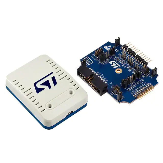
ST-LINK/V2
STMicroelectronics
-
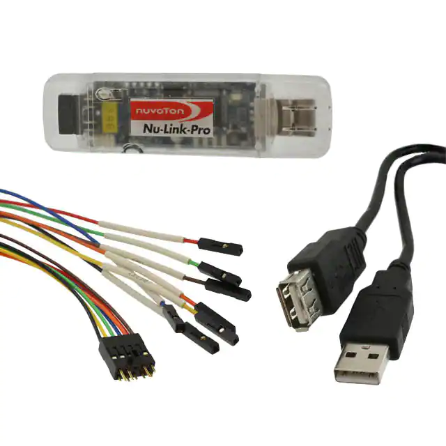
STLINK-V3SET
STMicroelectronics
-
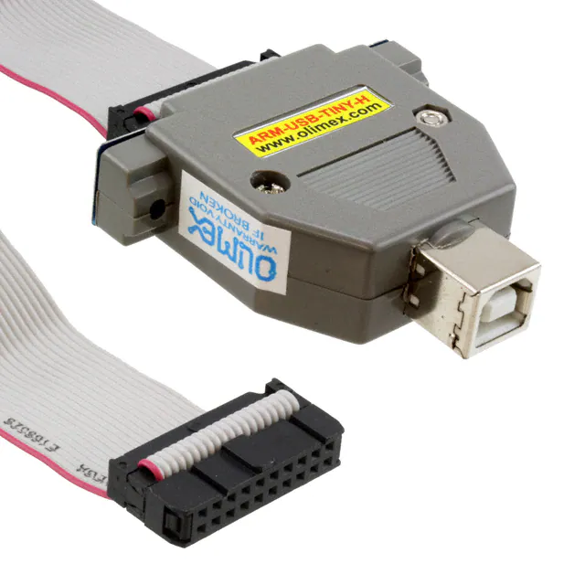
NU-LINK-PRO
Nuvoton Technology Corporation
-
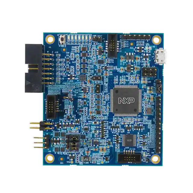
ARM-USB-TINY-H
Olimex LTD
-
MCU-LINK-PRO
NXP Semiconductors
-
410-308-B
Digilent, Inc.
Tech Hub

TTL and CMOS logic families differ in thresholds, loading, output drive, power and timing. This engineering guide compares 74HC and 74HCT, calculates noise margins and checks 3.3 V/5 V compatibility.

A practical engineering guide to 3.3V and 5V logic compatibility, input thresholds, resistor dividers, translator ICs, MOSFET level shifting, I2C pull-ups, timing limits and power-sequencing risks.

The 74HC595 uses push-pull logic outputs, while the TPIC6B595 uses 50 V open-drain DMOS sinks for higher-power loads. This guide compares timing, current limits, 3.3 V interfacing, load wiring, thermal…

The 74HC595 converts serial data into eight stable parallel outputs. This guide covers pin functions, shift and storage timing, OE and MR behavior, drive-current limits, cascading, voltage compatibilit…

A technical comparison of level-sensitive latches and edge-triggered flip-flops, covering timing windows, setup and hold limits, master–slave operation, time borrowing, race-through, HDL inference and…

A D latch stores one bit while Enable controls when data can pass. This reference covers gate-level operation, truth tables, transparency, setup and hold timing, LE versus OE, common ICs and practical …

An SR latch stores one bit through cross-coupled feedback. This engineering reference covers NOR and NAND implementations, truth tables, forbidden-state recovery, gated operation, switch debouncing, fa…

Latch circuits retain one bit through feedback. This technical reference covers SR and D latches, truth tables, transparency, timing limits, latch-versus-flip-flop behavior, applications and common log…

An engineering guide to LED driver operation, constant-current and constant-voltage outputs, linear and switching topologies, dimming, IC selection, calculations, replacement compatibility, and fault c…

Operational amplifier guide covering op amp basics, feedback, ideal vs real op amps, common configurations, buffer circuits, offset, bias current, gain-bandwidth, slew rate, rail-to-rail limits and sel…


