
 My Inquiry
 My Account


Analog Devices Inc. AD260AND-5
- Part No.:
- AD260AND-5
- Manufacturer:
- Analog Devices Inc.
- Category:
- Digital Isolators
- Package:
- 22-DIP Module
- Datasheet:
-
 AD260AND-5.pdf
- Description:
- DGTL ISO 1.75KV GEN PURP 22DIP
- Quantity:
- Payment:

- Shipping:

Inventory:1,580
Please send an inquiry. Send us your inquiry, and we will respond immediately.
Product details
Overview
AD260AND-5 from Analog Devices is a high-speed logic isolator with integrated 37 Vp-p isolated power transformer, designed for unidirectional field-to-system signal isolation in industrial control systems. It provides five isolated input channels (S0–S4), 20 MHz bandwidth, 14 ns propagation delay, and 3.5 kVrms isolation rating - enabling robust digital I/O isolation in PLC analog I/O cards and motor drive controls.
For engineers reviewing the AD260AND-5 datasheet, AD260AND-5 pinout, AD260AND-5 application, or AD260AND-5 equivalent, key selection criteria include its 5-input/0-output configuration, system-side three-state enable (ENABLESYS), field-side power supply generation capability (PWRxFLD pins), and compatibility with HCMOS/ACMOS logic levels across –25°C to +85°C.
Technical Context
The AD260AND-5 implements Analog Devices' IsoLogic™ architecture using capacitive-coupled data transmission across a 3.5 kVrms isolation barrier, with each of its five input lines featuring Schmitt-trigger inputs and latch-based continuous update circuitry. Its integral center-tapped transformer supports push-pull drive at 150–300 kHz to deliver up to 1.5 W of isolated field-side power.
Unlike optocouplers, the AD260AND-5 achieves nanosecond-level edge symmetry (±1 ns) and maintains output validity within 12 µs after power-up reset or fault recovery via background input polling every ~5 µs. All five inputs are unidirectional (S0–S4 → F0–F4), with no output drivers on the field side - confirmed by pin function table and AD260BND-5 schematic.
Key Specifications
| Parameter | Value and Actual Design Meaning |
|---|---|
| Isolation Rating | 3.5 kVrms test voltage (100% production tested); enables compliance with UL1950, IEC950, EN60950 safety standards. |
| Logic Bandwidth | 20 MHz minimum (NRZ data rate up to 40 Mbps); supports high-speed digital I/O in motor drives and DCS systems. |
| Propagation Delay | 14 ns typical (tPHL/tPLH); ensures tight timing alignment for time-critical PWM or encoder signals. |
| Edge Symmetry Error | ±1 ns max (tPHL vs. tPLH); preserves waveform fidelity for accurate isolation of timing-sensitive signals. |
| Input Threshold (VT+) | 2.7 V typical at +5 VdcSYS; compatible with standard 5 V HCMOS/ACMOS logic families. |
| Power Transformer Output | 37 Vp-p at 5 V push-pull drive; enables regulation to ±5 V, +24 V, or other field-side rails up to 1.5 W. |
| Common-Mode Transient Immunity | ≥10 kV/µs; prevents false triggering in noisy industrial environments like IGBT gate drive circuits. |
Pinout & Package
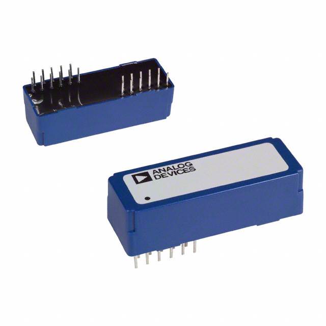
AD260AND-5 is housed in a 22-lead plastic DIP (ND-22) package with ≥18 mm creepage distance between system and field sides, supporting 750 V mains isolation per CSA/IEC standards. Pin 1 is marked with a notch; system-side pins occupy positions 1–8 and 15–17; field-side pins occupy positions 18–22 and 9–14 (with DRVA/DRVCT/DRVB/PWRBFLD/PWRCTFLD/PWRAFLD active).
| Pin/Terminal | Circuit Role | Design Meaning |
|---|---|---|
| 1–5 (S0–S4) | System-side digital inputs | Unidirectional logic inputs accepting HCMOS/ACMOS levels; must be tied high/low (not floating). |
| 6 (ENABLESYS) | System output enable | Three-states all system-side outputs (DRVA/DRVCT/DRVB); used for multiplexing multiple AD260s. |
| 7 (+5 VdcSYS) | System power supply | 4.5–5.5 V DC input; bypassed internally (0.05 µF) and externally (0.01 µF recommended). |
| 8 (5 V RTNSYS) | System ground reference | Return path for system-side supply; requires low-inductance connection to minimize noise coupling. |
| 15 (5 V RTNFLD) | Field power return | Ground reference for field-side isolated power; electrically isolated from 5 V RTNSYS. |
| 16 (+5 VdcFLD) | Field power supply | Regulated output derived from transformer secondary; powers field-side logic and regulators. |
| 17 (ENABLEFLD) | Field output enable | Three-states all field-side outputs (F0–F4); allows presetting logic levels at power-up via pull-ups/downs. |
| 18–22 (F0–F4) | Field-side digital outputs | Isolated logic outputs driven by S0–S4; no internal drivers - configured as receivers only in AD260AND-5. |
| 9 (DRVA), 10 (DRVCT), 11 (DRVB) | Transformer primary drive | Push-pull driver interface for system-side transformer excitation (150–300 kHz). |
| 12 (PWRBFLD), 13 (PWRCTFLD), 14 (PWRAFLD) | Transformer secondary taps | Provide access to center-tapped secondary winding for rectification and regulation of isolated field power. |
Key Features
| Feature | Design Value |
|---|---|
| Five-channel unidirectional isolation | Enables complete separation of field-side sensor/actuator inputs from system-side MCU without bidirectional contention. |
| Integrated 1.5 W isolated power transformer | Eliminates need for external isolated DC/DC converter; reduces BOM count and board space in PLC I/O modules. |
| Continuous update mode | Guarantees valid output state within 12 µs after power-up or fault, even without input transitions - critical for safe startup. |
| 10 kV/µs common-mode transient immunity | Prevents spurious switching during fast transients in motor drive or relay switching environments. |
| Pin-compatible family with six I/O configurations | Allows design reuse across input/output variants (e.g., AD260AND-0 to AD260AND-5) without PCB layout changes. |
Applications
| PLC Analog Input Card | IGBT Motor Drive Control |
|---|---|
Use Scenario: Isolating 5-channel thermocouple or RTD sensor inputs from backplane MCU in modular PLC chassis. IC Role / Device Role / Timing Role: AD260AND-5 receives raw field-side analog front-end status bits and fault flags, transmitting them across isolation barrier to system controller. Use Value: Enables safe, noise-immune acquisition of field data while supplying isolated +5 VdcFLD to sensor signal conditioning circuitry. | Use Scenario: Transmitting five independent gate enable/disable commands from system-side PWM controller to isolated IGBT half-bridge drivers. IC Role / Device Role / Timing Role: AD260AND-5 acts as a high-speed, low-jitter digital isolator for gate drive logic, preserving edge timing integrity. Use Value: Delivers 14 ns propagation delay and ±1 ns edge symmetry to prevent shoot-through in high-frequency motor inverters. |
| Industrial Data Acquisition System | Distributed Control System (DCS) Node |
Use Scenario: Collecting discrete status signals (e.g., limit switches, valve positions) from hazardous-area field devices into central DAQ unit. IC Role / Device Role / Timing Role: AD260AND-5 serves as a 5-bit parallel input isolator, converting field-side dry-contact closures into clean system-side logic levels. Use Value: Provides 3.5 kVrms isolation and 10 kV/µs transient immunity to protect sensitive DAQ electronics from ground loops and surges. | Use Scenario: Interfacing local DCS node processor with remote fieldbus transceivers or analog output modules requiring isolated digital handshake signals. IC Role / Device Role / Timing Role: AD260AND-5 isolates five dedicated control/status lines (e.g., ready, error, sync, reset, enable) between DCS CPU and field module. Use Value: Integrates isolated power generation (via PWRxFLD pins) to eliminate separate isolated DC/DC converters in compact node designs. |
Equivalent & Alternatives
The following parts are listed as comparable options for similar high-speed logic isolation applications.
| Alternative Part | Technical Difference | Application Difference | Selection Advice |
|---|---|---|---|
| ADuM1300ARW | 3-channel, 100 Mbps, 2.5 kVrms, no integrated power transformer | Requires external isolated power; lower channel count; higher data rate but no field-side power generation | Choose when only 3 channels needed and external DC/DC acceptable; not drop-in for AD260AND-5's 5-input + power role. |
| Si8650BD-B-IS | 5-channel, 150 Mbps, 5 kVrms, no integrated transformer, 3.3 V only | No isolated power capability; incompatible supply voltage; higher isolation rating but no field-side rail generation | Choose for higher-speed, higher-isolation 3.3 V systems where external power is available; not suitable for 5 V field-side power needs. |
Compared with ADuM1300ARW and Si8650BD-B-IS, the AD260AND-5 uniquely combines five 20 MHz input channels with an integral 1.5 W isolated power transformer - making it the only option that eliminates both discrete optocouplers and isolated DC/DC converters in 5 V industrial I/O designs.
Availability
AD260AND-5 is available at Aetrix Electronics and suitable for PLC/DCS analog I/O cards, IGBT motor drive controls, industrial data acquisition systems, distributed control system nodes, and high-speed digital I/O ports requiring stable component supply and long-term industrial lifecycle support.
Supply support for AD260AND-5 includes scheduled delivery planning, volume procurement assistance, BOM continuity management, traceable sourcing, and lifecycle availability coordination for OEM customers, industrial embedded developers, connected-device designers, and electronics production programs.
Manufacturer
Analog Devices, Inc. is a global leader in high-performance analog, mixed-signal, and digital signal processing semiconductors, headquartered in Norwood, MA.
The AD260 series belongs to Analog Devices' IsoLogic™ isolator product line, engineered specifically for industrial automation applications demanding simultaneous high-speed digital isolation and integrated isolated power generation in a single package.
FAQ
What is the isolation voltage rating of the AD260AND-5?
The AD260AND-5 is rated for 3.5 kVrms isolation test voltage (100% production tested), with an operating isolation voltage of 1.25 kVrms. This meets UL1950, IEC950, and EN60950 safety requirements and supports 750 V mains isolation via ≥18 mm creepage spacing in the ND-22 package. The AD260AND-5 achieves this using Analog Devices' proprietary IsoLogic™ capacitive isolation architecture.
Does the AD260AND-5 provide isolated power, and how is it used?
Yes, the AD260AND-5 integrates a center-tapped transformer capable of delivering up to 1.5 W of isolated field-side power. Driven push-pull at 150–300 kHz on the system side (pins DRVA/DRVCT/DRVB), it generates 37 Vp-p on the secondary (pins PWRAFLD/PWRCTFLD/PWRBFLD), which can be rectified and regulated to ±5 V, +24 V, or other required field-side rails. This eliminates the need for an external isolated DC/DC converter in the AD260AND-5 design.
How does the AD260AND-5 handle power-up and fault recovery?
The AD260AND-5 features a continuous update circuit that polls all five inputs every ~5 µs. After power-up (when +5 VdcSYS and +5 VdcFLD exceed 3.3 V), it enters a ~30 µs reset interval, after which outputs reflect valid input states within 12 µs - even without input transitions. This guarantees deterministic behavior during startup or after fault conditions, a critical requirement for safe industrial control systems using the AD260AND-5.
What are the logic voltage levels supported by the AD260AND-5 inputs and outputs?
The AD260AND-5 inputs (S0–S4) accept standard 5 V HCMOS/ACMOS logic levels, with typical VT+ = 2.7 V and VT− = 1.8 V at +5 VdcSYS. Outputs (F0–F4) drive CMOS-compatible loads: VOH = 3.7 V min at 4 mA, VOL = 0.4 V max at 4 mA. Both sides operate from 4.5–5.5 V supplies, with quiescent current of 4 mA per side - confirmed in the AD260AND-5 datasheet specifications table.
Can the AD260AND-5 be used in bidirectional communication?
No - the AD260AND-5 is strictly unidirectional: inputs on the system side (S0–S4), outputs on the field side (F0–F4). Its pin configuration (per Table I and AD260BND-5 schematic) confirms zero output drivers on the system side and zero input receivers on the field side. For bidirectional isolation, other AD260 variants (e.g., AD260AND-2 or AD260AND-3) or alternative isolators must be selected; the AD260AND-5 is optimized for field-to-system monitoring only.
AD260AND-5 Specifications
- Product attributes
- Attribute value
- Manufacturer:
- Analog Devices Inc.
- Series:
- IsoLogic™
- Package/Case:
- 22-DIP Module
- Packaging:
- Tube
- Product Status:
- Obsolete
- Technology:
- Magnetic Coupling
- Type:
- General Purpose
- Isolated Power:
- Yes
- Number of Channels:
- 5
- Inputs - Side 1/Side 2:
- 5/0
- Channel Type:
- Unidirectional
- Voltage - Isolation:
- 1750Vrms
- Common Mode Transient Immunity (Min):
- 10kV/µs
- Data Rate:
- -
- Propagation Delay tpLH / tpHL (Max):
- 25ns, 25ns
- Pulse Width Distortion (Max):
- -
- Rise / Fall Time (Typ):
- -
- Voltage - Supply:
- 4V ~ 5.75V
- Grade:
- -
- Qualification:
- -
- Operating Temperature:
- -25°C ~ 85°C
- Mounting Type:
- Through Hole
- Supplier Device Package:
- 22-PDIP
AD260AND-5 FAQ
1.How can I place an order for AD260AND-5 through Aetrix?
Please submit a Request for Quotation (RFQ) for AD260AND-5 on Aetrix. Our sales agent will provide a competitive quotation and guide you through the order confirmation once you accept the terms.
2.Are the price and stock information for AD260AND-5 reliable?
The price and inventory of AD260AND-5 are updated periodically and may fluctuate due to market conditions. Stock and pricing data are typically refreshed every 24 hours. Quotation validity for AD260AND-5 is usually 5 days.
3.What payment methods are accepted for AD260AND-5?
We accept Wire Transfer, PayPal, Credit Card, Western Union, MoneyGram, and Escrow for AD260AND-5 transactions.
Note: Certain payment methods may incur a processing fee.
4.How is shipping managed for AD260AND-5?
AD260AND-5 orders can be shipped via leading logistics carriers, including DHL, UPS, FedEx, TNT, or Registered Mail.
Once your AD260AND-5 order is processed, you will receive an email with the shipment details and tracking number.
Note: Tracking information may take up to 24 hours to appear. Express delivery typically takes 3–5 business days.
5.How can I obtain technical support or documentation for AD260AND-5?
For technical support, including AD260AND-5 datasheets, pinout diagrams, or application guidance, please contact our engineering support team. They can provide detailed documentation and assistance for your AD260AND-5 requirements.
6.How does Aetrix verify that AD260AND-5 is sourced from the original manufacturer or authorized distributors?
All AD260AND-5 products on Aetrix are procured from qualified distributors and authorized channels. Our dedicated quality assurance team conducts strict verification, including traceability checks and, if necessary, third-party testing. This ensures that AD260AND-5 meets industry standards.
7.What is the process for return or replacement of AD260AND-5?
All AD260AND-5 units undergo pre-shipment inspection (PSI). If there is an issue with AD260AND-5, returns or replacements are accepted under the following conditions:
1.Quantity discrepancies, incorrect items, or visible external defects (such as breakage or corrosion), acknowledged by Aetrix.
2.The issue is reported within 90 days of delivery.
3.The AD260AND-5 part is unused and in its original packaging.
Return procedure for AD260AND-5:
1.Submit a request within 90 days.
2.Obtain a Return Material Authorization (RMA) from Aetrix.
AD260AND-5 Tags

-
ISO1212DBQR
Texas Instruments
-
ISO6721BDR
Texas Instruments
-
SI8710AC-B-ISR
Skyworks Solutions Inc.
-
ISO7720FDR
Texas Instruments
-
ISO7721DR
Texas Instruments
-
ISO7721FDR
Texas Instruments
-
SI8710CC-B-ISR
Skyworks Solutions Inc.
-
ISO6741FQDWRQ1
Texas Instruments

-
ISO7721DWVR
Texas Instruments
-
ISO7762FDBQR
Texas Instruments

-
ISO7741DWR
Texas Instruments
-
ISO7741FDWR
Texas Instruments
Tech Hub

A practical engineering guide to 3.3V and 5V logic compatibility, input thresholds, resistor dividers, translator ICs, MOSFET level shifting, I2C pull-ups, timing limits and power-sequencing risks.

The 74HC595 uses push-pull logic outputs, while the TPIC6B595 uses 50 V open-drain DMOS sinks for higher-power loads. This guide compares timing, current limits, 3.3 V interfacing, load wiring, thermal…

The 74HC595 converts serial data into eight stable parallel outputs. This guide covers pin functions, shift and storage timing, OE and MR behavior, drive-current limits, cascading, voltage compatibilit…

A technical comparison of level-sensitive latches and edge-triggered flip-flops, covering timing windows, setup and hold limits, master–slave operation, time borrowing, race-through, HDL inference and…

A D latch stores one bit while Enable controls when data can pass. This reference covers gate-level operation, truth tables, transparency, setup and hold timing, LE versus OE, common ICs and practical …

An SR latch stores one bit through cross-coupled feedback. This engineering reference covers NOR and NAND implementations, truth tables, forbidden-state recovery, gated operation, switch debouncing, fa…

Latch circuits retain one bit through feedback. This technical reference covers SR and D latches, truth tables, transparency, timing limits, latch-versus-flip-flop behavior, applications and common log…

An engineering guide to LED driver operation, constant-current and constant-voltage outputs, linear and switching topologies, dimming, IC selection, calculations, replacement compatibility, and fault c…

Operational amplifier guide covering op amp basics, feedback, ideal vs real op amps, common configurations, buffer circuits, offset, bias current, gain-bandwidth, slew rate, rail-to-rail limits and sel…

Jumper cables guide covering safe connection order, red and black clamp placement, final ground connection, cable gauge, length, clamp quality, copper vs CCA cables, jump starter comparison and battery…


