
 My Inquiry
 My Account


Texas Instruments AD3421QRWERQ1
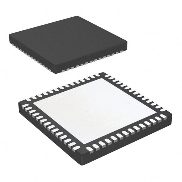
- Part No.:
- AD3421QRWERQ1
- Manufacturer:
- Texas Instruments
- Category:
- Analog to Digital Converters (ADC)
- Package:
- 56-VFQFN Exposed Pad
- Datasheet:
-
 AD3421QRWERQ1.pdf
- Description:
- IC ADC 12BIT PIPELINED 56VQFNP
- Quantity:
- Payment:

- Shipping:

Inventory:3,040
Please send an inquiry. Send us your inquiry, and we will respond immediately.
Product details
Overview
ADC3421QRWERQ1 from Texas Instruments is an AEC-Q100 Grade 1 automotive quad-channel, 12-bit, 25-MSPS analog-to-digital converter with serial LVDS interface, 71.1 dBFS SNR at 10 MHz input, 90 dBc SFDR, and 105 dB channel isolation-designed for solid-state LiDAR and radar signal acquisition.
For engineers reviewing the ADC3421QRWERQ1 datasheet, ADC3421QRWERQ1 pinout, ADC3421QRWERQ1 application, or ADC3421QRWERQ1 equivalent, key selection considerations include multichip synchronization support via SYSREF, flexible input clock division (÷1/÷2/÷4), ultra-low 44 mW/channel power at 25 MSPS, and VQFNP-56 package thermal performance (RθJA = 20.3°C/W).
Technical Context
The ADC3421QRWERQ1 employs a high-linearity sampling architecture with internal dither and chopper to enhance AC performance across wide input frequencies (up to 450 MHz analog bandwidth). Its PLL-based bit clock generation enables precise serialization of four 12-bit data streams over two-wire LVDS per channel.
System-level timing is coordinated through dedicated LVDS outputs for frame clock (FCLKP/FCLKM) and bit clock (DCLKP/DCLKM), while SYSREFP/SYSREFM inputs allow deterministic multidevice synchronization in phased-array or time-of-flight systems requiring sub-picosecond alignment.
Key Specifications
| Parameter | Value and Actual Design Meaning |
|---|---|
| Resolution | 12-bit-enables 4096 discrete amplitude levels for high-fidelity waveform capture in motor control feedback loops. |
| Sampling Rate | 25 MSPS-supports Nyquist-limited baseband signals up to 12.5 MHz or IF sampling of higher-frequency radar/LiDAR returns. |
| SNR @ 10 MHz | 71.1 dBFS-delivers >11.5 ENOB for accurate digitization of low-amplitude echo signals in noisy automotive environments. |
| Channel Isolation | 105 dB-prevents crosstalk between adjacent channels during simultaneous multi-sensor acquisition in smart antenna arrays. |
| Power per Channel | 44 mW at 25 MSPS-reduces thermal load in space-constrained ADAS ECUs without compromising dynamic range. |
| Analog Bandwidth | 540 MHz (3 dB)-allows direct sampling of RF-modulated signals up to L-band without external downconversion. |
| Supply Voltage | 1.8 V AVDD/DVDD-simplifies power delivery in modern 1.8-V automotive SoC domains and reduces I²R losses. |
Pinout & Package
VQFNP-56 (8.00 mm × 8.00 mm) thermally enhanced QFN package with exposed thermal pad connected to ground; supports high-density PCB layout and efficient heat dissipation in automotive under-hood applications.
| Pin/Terminal | Circuit Role | Design Meaning |
|---|---|---|
| INAP / INAM | Differential analog input (Channel A) | Accepts 2-VPP full-scale differential signal; common-mode voltage referenced to VCM output (0.95 V). |
| DA0P / DA0M DA1P / DA1M | LVDS serial data outputs (Channel A) | Two-wire LVDS interface carries serialized 12-bit samples; eliminates parallel bus routing congestion. |
| FCLKP / FCLKM DCLKP / DCLKM | LVDS frame & bit clock outputs | Provides synchronous timing for data recovery; enables deterministic latency (9 clock cycles in 2-wire mode). |
| SYSREFP / SYSREFM | Differential system reference input | Enables JESD204B-like multichip synchronization for phase-coherent sampling across multiple ADC3421QRWERQ1 devices. |
| PDN / RESET | Power-down & hardware reset | PDN supports SPI-configurable low-power states; RESET provides asynchronous device initialization with internal 150-kΩ pulldown. |
Key Features
| Feature | Design Value |
|---|---|
| AEC-Q100 Grade 1 qualification | Validated for continuous operation from –40°C to +125°C junction temperature in safety-critical ADAS modules. |
| Quad-channel 12-bit ADC | Four independent converters on single die-replaces four discrete ADCs, reducing BOM count and inter-channel skew. |
| Serial LVDS interface | Reduces interface pin count by >60% vs parallel CMOS; supports high-density routing in compact radar sensor modules. |
| Input clock divider (÷1/÷2/÷4) | Allows use of common system clocks (e.g., 100 MHz) without requiring dedicated high-frequency ADC clocks. |
| Multichip synchronization | Enables time-aligned sampling across distributed sensors-critical for beamforming in smart antenna arrays. |
Applications
| Solid-State LiDAR | Radar Signal Acquisition |
|---|---|
Use Scenario: Digitizing time-of-flight return pulses from laser diodes reflected off vehicles or pedestrians. IC Role / Device Role / Timing Role: Quad-channel ADC captures synchronized analog echoes from multiple photodiode arrays with <150 ps aperture delay matching. Use Value: 105 dB channel isolation prevents ghosting artifacts; 71.1 dBFS SNR ensures detection of weak long-range returns amid ambient light noise. | Use Scenario: Sampling intermediate frequency (IF) outputs from automotive radar transceivers (e.g., 77 GHz FMCW). IC Role / Device Role / Timing Role: High-linearity 12-bit conversion of modulated IF signals up to 450 MHz bandwidth for FFT-based target detection. Use Value: 540 MHz analog bandwidth enables direct IF sampling; 90 dBc SFDR suppresses spurious responses that could mask small targets near large clutter. |
| Motor Control Feedback | Nondestructive Testing |
Use Scenario: Capturing high-fidelity current/voltage waveforms from inverter legs in electric powertrain inverters. IC Role / Device Role / Timing Role: Simultaneous sampling of phase currents and DC-link voltage using four independent channels with matched latency. Use Value: 44 mW/channel ultra-low power minimizes self-heating in sealed motor controllers; 12-bit resolution supports precise field-oriented control algorithms. | Use Scenario: Digitizing ultrasonic transducer return signals in industrial weld inspection equipment. IC Role / Device Role / Timing Role: High-SNR acquisition of microsecond-duration acoustic echoes with minimal added noise floor. Use Value: 71.1 dBFS SNR at 10 MHz enables detection of subtle material discontinuities; dither/chopper features reduce harmonic distortion in narrowband analysis. |
Equivalent & Alternatives
The following parts are listed as comparable options for similar quad-channel, 12-bit, automotive ADC applications.
| Alternative Part | Technical Difference | Application Difference | Selection Advice |
|---|---|---|---|
| ADC34J22IRSBT | Same 12-bit, 50-MSPS architecture but non-automotive grade; lacks AEC-Q100 qualification and Grade 1 temperature range. | Targeted at industrial test equipment-not certified for automotive safety-critical systems. | Select only for non-automotive designs where cost or higher speed justifies absence of automotive qualification. |
| ADS4149IRGZT | 14-bit, 250-MSPS, single-channel ADC; no multichannel synchronization or SYSREF support; different LVDS framing protocol. | Used in high-speed communications receivers-not suitable for synchronized multi-sensor acquisition. | Choose when higher resolution and speed outweigh need for quad-channel correlation and automotive compliance. |
Compared with ADC3421QRWERQ1, ADC34J22IRSBT offers higher sampling rate but no automotive qualification, while ADS4149IRGZT delivers greater resolution and speed at the cost of channel count, synchronization capability, and automotive suitability-making ADC3421QRWERQ1 uniquely balanced for ADAS sensor fusion.
Availability
ADC3421QRWERQ1 is available at Aetrix Electronics and suitable for solid-state LiDAR, radar signal acquisition, and motor control feedback systems requiring stable component supply across extended automotive temperature ranges and long production lifecycles.
Supply support for ADC3421QRWERQ1 includes scheduled delivery planning, volume procurement assistance, BOM continuity management, traceable sourcing, and lifecycle availability coordination for OEM customers, industrial embedded developers, connected-device designers, and electronics production programs.
Manufacturer
Texas Instruments is a global semiconductor leader specializing in analog, embedded processing, and automotive ICs-with deep expertise in high-performance data converters for safety-critical systems.
The ADC3421QRWERQ1 belongs to TI's automotive-qualified high-speed ADC portfolio, engineered specifically for demanding ADAS applications including LiDAR, radar, and real-time motor control where precision, reliability, and multichip timing coherence are essential.
FAQ
What is the maximum analog input frequency supported by the ADC3421QRWERQ1?
The ADC3421QRWERQ1 supports analog input frequencies up to 450 MHz (3 dB bandwidth) with a 2-VPP differential full-scale input. At 230 MHz input, it maintains 68.9 dBFS SNR and 82 dBc SFDR-enabling direct RF sampling in automotive radar front-ends without external downconversion stages. This bandwidth is confirmed in Section 6.5 of the SBAS958A datasheet.
Does the ADC3421QRWERQ1 support JESD204B interface?
No, the ADC3421QRWERQ1 does not implement JESD204B. It uses a proprietary two-wire serial LVDS interface with separate frame and bit clocks (FCLKP/FCLKM, DCLKP/DCLKM). While it supports multichip synchronization via SYSREFP/SYSREFM-similar in intent to JESD204B subclass 1-it lacks the embedded link layer, lane alignment, and error detection of JESD204B. The ADC3421QRWERQ1 interface is defined in Section 6.9 of SBAS958A.
What is the typical power consumption of the ADC3421QRWERQ1 at 25 MSPS?
At 25 MSPS, the ADC3421QRWERQ1 consumes 44 mW per channel (176 mW total), with 54–71 mA analog supply current (AVDD) and 45–71 mA digital supply current (DVDD) across temperature. Total power dissipation is specified as 177–240 mW in Section 6.5. This ultra-low power enables thermal management in compact ADAS sensor housings without active cooling.
How is multichip synchronization implemented on the ADC3421QRWERQ1?
Multichip synchronization on the ADC3421QRWERQ1 is implemented via differential SYSREFP/SYSREFM inputs that align internal sampling clocks and data framing across multiple devices. When driven synchronously, SYSREF triggers deterministic latency (9 clock cycles in default 2-wire mode) and enables phase-coherent sampling for beamforming or time-of-flight calculations. This capability is detailed in Sections 3, 8.3, and 8.4 of SBAS958A.
What package type and thermal characteristics does the ADC3421QRWERQ1 use?
The ADC3421QRWERQ1 uses the VQFNP-56 (8.00 mm × 8.00 mm) thermally enhanced QFN package with an exposed thermal pad. Its thermal metrics include RθJA = 20.3°C/W, RθJC(bot) = 0.7°C/W, and ψJB = 5.6°C/W-enabling effective heat transfer to the PCB ground plane. These values are specified in Section 6.4 of SBAS958A and validated per JEDEC JESD51 standards.
AD3421QRWERQ1 Specifications
- Product attributes
- Attribute value
- Manufacturer:
- Texas Instruments
- Series:
- -
- Package/Case:
- 56-VFQFN Exposed Pad
- Packaging:
- Tape & Reel (TR)
- Product Status:
- Active
- Number of Bits:
- 12
- Sampling Rate (Per Second):
- 25M
- Number of Inputs:
- 4
- Input Type:
- Differential
- Data Interface:
- LVDS - Serial
- Configuration:
- ADC
- Ratio - S/H:ADC:
- 0:1
- Number of A/D Converters:
- 4
- Architecture:
- Pipelined
- Reference Type:
- External
- Voltage - Supply, Analog:
- 1.7V ~ 1.9V
- Voltage - Supply, Digital:
- 1.7V ~ 1.9V
- Features:
- Simultaneous Sampling
- Operating Temperature:
- -40°C ~ 125°C
- Supplier Device Package:
- 56-VQFNP (8x8)
- Mounting Type:
- Surface Mount, Wettable Flank
- Grade:
- Automotive
- Qualification:
- AEC-Q100
AD3421QRWERQ1 FAQ
1.How can I place an order for AD3421QRWERQ1 through Aetrix?
Please submit a Request for Quotation (RFQ) for AD3421QRWERQ1 on Aetrix. Our sales agent will provide a competitive quotation and guide you through the order confirmation once you accept the terms.
2.Are the price and stock information for AD3421QRWERQ1 reliable?
The price and inventory of AD3421QRWERQ1 are updated periodically and may fluctuate due to market conditions. Stock and pricing data are typically refreshed every 24 hours. Quotation validity for AD3421QRWERQ1 is usually 5 days.
3.What payment methods are accepted for AD3421QRWERQ1?
We accept Wire Transfer, PayPal, Credit Card, Western Union, MoneyGram, and Escrow for AD3421QRWERQ1 transactions.
Note: Certain payment methods may incur a processing fee.
4.How is shipping managed for AD3421QRWERQ1?
AD3421QRWERQ1 orders can be shipped via leading logistics carriers, including DHL, UPS, FedEx, TNT, or Registered Mail.
Once your AD3421QRWERQ1 order is processed, you will receive an email with the shipment details and tracking number.
Note: Tracking information may take up to 24 hours to appear. Express delivery typically takes 3–5 business days.
5.How can I obtain technical support or documentation for AD3421QRWERQ1?
For technical support, including AD3421QRWERQ1 datasheets, pinout diagrams, or application guidance, please contact our engineering support team. They can provide detailed documentation and assistance for your AD3421QRWERQ1 requirements.
6.How does Aetrix verify that AD3421QRWERQ1 is sourced from the original manufacturer or authorized distributors?
All AD3421QRWERQ1 products on Aetrix are procured from qualified distributors and authorized channels. Our dedicated quality assurance team conducts strict verification, including traceability checks and, if necessary, third-party testing. This ensures that AD3421QRWERQ1 meets industry standards.
7.What is the process for return or replacement of AD3421QRWERQ1?
All AD3421QRWERQ1 units undergo pre-shipment inspection (PSI). If there is an issue with AD3421QRWERQ1, returns or replacements are accepted under the following conditions:
1.Quantity discrepancies, incorrect items, or visible external defects (such as breakage or corrosion), acknowledged by Aetrix.
2.The issue is reported within 90 days of delivery.
3.The AD3421QRWERQ1 part is unused and in its original packaging.
Return procedure for AD3421QRWERQ1:
1.Submit a request within 90 days.
2.Obtain a Return Material Authorization (RMA) from Aetrix.
AD3421QRWERQ1 Tags
-
ADC081C021CIMKX/NOPB
Texas Instruments

-
MCP3021A5T-E/OT
Microchip Technology
-
TLA2024IRUGR
Texas Instruments
-
MCP3221A5T-E/OT
Microchip Technology
-
MCP3221A5T-I/OT
Microchip Technology
-
MCP3221A4T-E/OT
Microchip Technology
-
MCP3221A6T-E/OT
Microchip Technology
-
MCP3221A0T-E/OT
Microchip Technology
-
MCP3221A1T-E/OT
Microchip Technology

-
ADC121S021CIMFX/NOPB
Texas Instruments

-
MCP3001-I/MS
Microchip Technology

-
MCP3001-I/SN
Microchip Technology
Tech Hub

A practical engineering guide to 3.3V and 5V logic compatibility, input thresholds, resistor dividers, translator ICs, MOSFET level shifting, I2C pull-ups, timing limits and power-sequencing risks.

The 74HC595 uses push-pull logic outputs, while the TPIC6B595 uses 50 V open-drain DMOS sinks for higher-power loads. This guide compares timing, current limits, 3.3 V interfacing, load wiring, thermal…

The 74HC595 converts serial data into eight stable parallel outputs. This guide covers pin functions, shift and storage timing, OE and MR behavior, drive-current limits, cascading, voltage compatibilit…

A technical comparison of level-sensitive latches and edge-triggered flip-flops, covering timing windows, setup and hold limits, master–slave operation, time borrowing, race-through, HDL inference and…

A D latch stores one bit while Enable controls when data can pass. This reference covers gate-level operation, truth tables, transparency, setup and hold timing, LE versus OE, common ICs and practical …

An SR latch stores one bit through cross-coupled feedback. This engineering reference covers NOR and NAND implementations, truth tables, forbidden-state recovery, gated operation, switch debouncing, fa…

Latch circuits retain one bit through feedback. This technical reference covers SR and D latches, truth tables, transparency, timing limits, latch-versus-flip-flop behavior, applications and common log…

An engineering guide to LED driver operation, constant-current and constant-voltage outputs, linear and switching topologies, dimming, IC selection, calculations, replacement compatibility, and fault c…

Operational amplifier guide covering op amp basics, feedback, ideal vs real op amps, common configurations, buffer circuits, offset, bias current, gain-bandwidth, slew rate, rail-to-rail limits and sel…

Jumper cables guide covering safe connection order, red and black clamp placement, final ground connection, cable gauge, length, clamp quality, copper vs CCA cables, jump starter comparison and battery…


