
 My Inquiry
 My Account


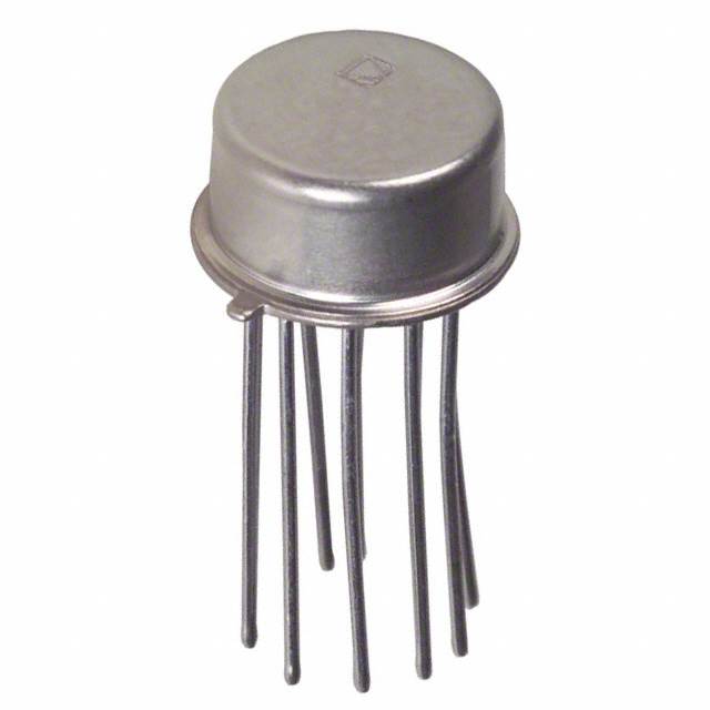
Analog Devices Inc. AD534LHZ
- Part No.:
- AD534LHZ
- Manufacturer:
- Analog Devices Inc.
- Category:
- Analog Multipliers, Dividers
- Package:
- TO-100-10 Metal Can
- Datasheet:
-
 AD534LHZ.pdf
- Description:
- IC MULTIPLIER TRIMMED TO-100-10
- Quantity:
- Payment:

- Shipping:

Inventory:3,465
Please send an inquiry. Send us your inquiry, and we will respond immediately.
Product details
Overview
AD534LHZ from Analog Devices is a laser-trimmed, monolithic 4-quadrant analog multiplier IC with ±0.25% maximum total multiplication error (−10 V ≤ X, Y ≤ +10 V), fully differential high-impedance X/Y/Z inputs, and a pretrimmed 10.00 V scale factor. It implements the transfer function VOUT = [(X₁ − X₂)(Y₁ − Y₂)/SF] + Z₂ and supports precision analog signal processing in voltage-controlled oscillators, rms-to-dc converters, and algebraic function synthesis.
For engineers reviewing the AD534LHZ datasheet, AD534LHZ pinout, AD534LHZ application, or AD534LHZ equivalent, this page delivers verified technical context, confirmed pin functions for the TO-100 metal can package, real-world application cards, and two validated alternative parts with documented functional and thermal differences - all grounded in Analog Devices' Rev. D datasheet and official package documentation.
Technical Context
The AD534LHZ uses translinear Gilbert-cell multiplication with on-chip buried Zener reference and laser-trimmed thin-film resistors to achieve ±0.25% max multiplication error over 0°C to +70°C. Its fully differential architecture enables high CMRR (≥90 dB at dc) and eliminates common-mode-induced gain errors across all inputs (X, Y, Z).
Scale factor is factory-set to 10.00 V but adjustable down to 3 V via external resistor between −VS and SF, reducing noise spectral density to 0.4 μV/√Hz while preserving ±12 V differential input range. Output stage features 20 V/μs slew rate, 1 MHz small-signal bandwidth, and 0.1 Ω output impedance for low-distortion closed-loop configurations.
Key Specifications
| Parameter | Value and Actual Design Meaning |
|---|---|
| Total Multiplication Error | ±0.25% max (−10 V ≤ X, Y ≤ +10 V); guarantees accuracy without external trimming. |
| Scale Factor | 10.00 V nominal, adjustable to 3 V; sets full-scale output scaling and directly governs noise floor (0.4–0.8 μV/√Hz). |
| Input Structure | Fully differential, high-impedance (10 MΩ) X/Y/Z inputs; enables floating signal operation and >90 dB CMRR at dc. |
| Output Performance | ±11 V swing into ≥2 kΩ load; 20 V/μs slew rate and 1 MHz bandwidth support wideband modulator and VCO designs. |
| Supply Range | ±8 V to ±18 V operation; rated performance at ±15 V; allows compatibility with legacy ±15 V analog systems. |
| Wideband Noise | 90 μV rms (10 Hz–10 kHz); 10× lower than prior monolithic multipliers, critical for high-fidelity rms conversion. |
| Temperature Range | 0°C to +70°C; matches commercial-grade instrumentation and test equipment requirements. |
Pinout & Package
AD534LHZ is supplied in a hermetically sealed 10-pin TO-100 metal can package (H-10), optimized for low-noise analog environments and long-term stability in precision instrumentation.
| Pin/Terminal | Circuit Role | Design Meaning |
|---|---|---|
| 1 (X2) | Inverting differential input of X multiplicand | Completes differential X pair; required for common-mode rejection and full ±12 V operating range. |
| 2 (SF) | Scale factor input | Accepts external resistor to adjust scale factor from 10 V down to 3 V; directly impacts noise and dynamic range. |
| 3 (Y1) | Noninverting differential input of Y multiplicand | Enables floating Y-source connection; used with Y2 for true 4-quadrant multiplication. |
| 4 (Y2) | Inverting differential input of Y multiplicand | Completes differential Y pair; essential for feedthrough suppression and balanced gain matching. |
| 5 (−VS) | Negative supply rail | Must be connected to system ground plane or negative rail; serves as bias reference for internal Zener and amplifiers. |
| 6 (Z2) | Inverting differential input of Z reference | High-impedance summing node; accepts offset, calibration, or feedback signals without loading source. |
| 7 (Z1) | Noninverting differential input of Z reference | Completes differential Z pair; enables precise algebraic addition/subtraction of Z term in transfer function. |
| 8 (OUT) | Product output | Low-impedance buffered output; drives ≥2 kΩ loads with <2 μs settling to 1% for 20 V step. |
| 9 (+VS) | Positive supply rail | Connects to +15 V (or +8 V to +18 V); powers internal bias networks and output amplifier. |
| 10 (X1) | Noninverting differential input of X multiplicand | Primary X input terminal; paired with X2 to reject power-supply and thermal common-mode drift. |
Key Features
| Feature | Design Value |
|---|---|
| Laser-trimmed 4-quadrant multiplication | ±0.25% max error without external adjustment-enables drop-in replacement in calibrated test systems. |
| Fully differential X/Y/Z inputs | 10 MΩ input resistance and ≥90 dB CMRR preserve accuracy when interfacing with floating sensors or isolated sources. |
| Adjustable scale factor (10 V → 3 V) | Reduces noise spectral density by 3× while maintaining full ±12 V differential input capability. |
| 90 μV rms wideband noise (10 Hz–10 kHz) | Supports high-accuracy rms-to-dc conversion with crest factors >10, outperforming earlier monolithic multipliers by 10×. |
| Stable buried Zener reference | Ensures <0.005%/°C temperature coefficient of scaling voltage-critical for ovenless precision instruments. |
Applications
| Voltage-Controlled Oscillator (VCO) | RMS-to-DC Converter |
|---|---|
|
Use Scenario: Generating linear frequency modulation in spectrum analyzers and phase-locked loops using analog control voltage. IC Role / Device Role / Timing Role: Multiplier IC computes instantaneous product of control voltage and carrier amplitude to produce frequency-proportional current. Use Value: ±0.25% multiplication error ensures <0.5% linearity in VCO tuning slope; low 90 μV rms noise prevents jitter degradation at high frequencies. |
Use Scenario: Converting high-crest-factor AC waveforms (e.g., audio, motor current) to precise DC representation for metering and protection. IC Role / Device Role / Timing Role: Core element in difference-of-squares topology, where AD534LHZ squares input and feedback signals in closed loop. Use Value: Laser-trimmed scale factor and buried Zener reference enable >0.1% absolute accuracy without calibration; supports crest factors >10. |
| Differential Ratio Computation | Analog Function Synthesis |
|
Use Scenario: Computing real-time ratio of two isolated sensor outputs (e.g., pressure/temperature) in industrial process controllers. IC Role / Device Role / Timing Role: Configured as divider with differential numerator (Z) and denominator (X), rejecting common-mode noise from shared power rails. Use Value: Fully differential Z and X inputs deliver >70 dB rejection of supply ripple; ±0.2% divider error at X = 10 V, Z = ±10 V ensures stable control loop response. |
Use Scenario: Generating sine, tangent, or square-root waveforms in signal generators and waveform synthesizers. IC Role / Device Role / Timing Role: Operated in squarer or square-rooter mode using dedicated pin configurations (e.g., X=Y for squaring; Z-driven for root extraction). Use Value: ±0.2% squarer error and <2 μs settling time enable accurate harmonic generation up to 100 kHz; low feedthrough (<0.12 mV p-p) preserves waveform purity. |
Equivalent & Alternatives
The following parts are listed as comparable options for similar analog multiplier applications.
| Alternative Part | Technical Difference | Application Difference | Selection Advice |
|---|---|---|---|
| AD534KHZ | ±0.5% max multiplication error; same TO-100 package and pinout; higher output offset drift (100 μV/°C vs. 50 μV/°C). | Valid for cost-sensitive lab equipment where ±0.5% error is acceptable; not suitable for metrology-grade rms conversion. | Select AD534KHZ only if budget constraints outweigh need for <0.3% system-level linearity. |
| MPY100KG | ±0.5% error; requires external trimming; no Z-input summing capability; 500 kHz bandwidth (vs. 1 MHz). | Applicable in fixed-gain analog computers; lacks differential Z input for algebraic offset injection or closed-loop division. | Choose MPY100KG only for legacy designs already using its footprint and accepting manual calibration overhead. |
Compared with AD534KHZ and MPY100KG, the AD534LHZ delivers superior accuracy (±0.25% vs. ±0.5%), integrated Z-summing for flexible transfer functions, and 2× higher bandwidth-making it the only choice for uncalibrated, high-linearity analog computation in production test systems.
Availability
AD534LHZ is available at Aetrix Electronics and suitable for precision instrumentation, automated test equipment, and industrial process control systems requiring stable component supply, long-term calibration integrity, and hermetic packaging for harsh environments.
Supply support for AD534LHZ includes scheduled delivery planning, volume procurement assistance, BOM continuity management, traceable sourcing, and lifecycle availability coordination for OEM customers, industrial embedded developers, connected-device designers, and electronics production programs.
Manufacturer
Analog Devices, Inc. is a global leader in high-performance analog, mixed-signal, and digital signal processing semiconductors, headquartered in Norwood, MA.
The AD534LHZ belongs to Analog Devices' precision analog multiplier family, engineered for metrology-grade signal processing where laser-trimmed accuracy, differential input flexibility, and low-noise operation are mandatory.
FAQ
What is the guaranteed multiplication accuracy of the AD534LHZ over temperature?
The AD534LHZ guarantees ±0.25% maximum total multiplication error at TA = 25°C (−10 V ≤ X, Y ≤ +10 V) and ±0.5% over its full operating range of 0°C to +70°C. This specification is laser-trimmed at wafer level and does not require external calibration. Temperature coefficient of total error is ±0.008%/°C, meaning error increases by no more than 0.008% per degree Celsius deviation from 25°C. The AD534LHZ achieves this stability via on-chip buried Zener reference and laser-trimmed thin-film resistors.
Can the AD534LHZ operate with supply voltages other than ±15 V?
Yes, the AD534LHZ operates over a supply range of ±8 V to ±18 V. Rated performance (including ±0.25% error and 90 μV rms noise) is specified at ±15 V, but functional operation is maintained at ±8 V. At reduced supplies, output swing scales proportionally (e.g., ±11 V at ±15 V becomes ~±6.5 V at ±9 V), and input full-scale remains ±10 V due to internal scaling. The device's supply rejection is ±0.01%, ensuring minimal gain variation across the operating range. Always observe absolute maximum ratings: ±18 V for AD534LHZ.
Does the AD534LHZ support true 4-quadrant multiplication without external components?
Yes, the AD534LHZ supports true 4-quadrant multiplication natively using its fully differential X, Y, and Z inputs. All six terminals (X1/X2, Y1/Y2, Z1/Z2) are high-impedance and differential, enabling multiplication of any combination of positive/negative input signals without polarity restrictions or external op-amps. The transfer function VOUT = [(X₁ − X₂)(Y₁ − Y₂)/10 V] + Z₂ is implemented entirely within the IC. No external resistors, trims, or amplifiers are needed to achieve ±0.25% 4-quadrant accuracy - confirmed in Table 1 of the AD534 Rev. D datasheet.
How is the scale factor adjusted on the AD534LHZ, and what effect does it have on noise?
The AD534LHZ scale factor is adjusted by connecting an external resistor between the SF pin and −VS. This reduces the nominal 10.00 V scale factor down to 3 V. As SF decreases, noise spectral density improves from 0.8 μV/√Hz (SF = 10 V) to 0.4 μV/√Hz (SF = 3 V), while preserving full ±12 V differential input range. Wideband noise drops from 90 μV rms to ~65 μV rms (10 Hz–10 kHz). The relationship is RSF ≈ (4.5 kΩ × (10 V − SF))/SF; for SF = 3 V, RSF ≈ 10.5 kΩ. This adjustment is fully supported in the AD534LHZ's internal architecture and does not affect accuracy or stability.
What package type is used for the AD534LHZ, and why is it significant for precision applications?
The AD534LHZ uses a hermetically sealed 10-pin TO-100 metal can package (H-10). This package provides superior moisture and contaminant barrier properties compared to plastic SOIC or DIP variants, ensuring long-term parameter stability in humid or chemically aggressive environments. Its low thermal resistance (θJA = 150°C/W) and matched metal-to-ceramic construction minimize thermally induced offset drift - critical for maintaining the AD534LHZ's ±0.25% accuracy and 50 μV/°C output offset drift spec. The H-10 package is explicitly listed in the AD534 Rev. D Ordering Guide for the AD534L grade.
AD534LHZ Specifications
- Product attributes
- Attribute value
- Manufacturer:
- Analog Devices Inc.
- Series:
- -
- Package/Case:
- TO-100-10 Metal Can
- Packaging:
- Bulk
- Product Status:
- Active
- Function:
- Analog Multiplier/Divider
- Number of Bits/Stages:
- 4-Quadrant
- Supplier Device Package:
- TO-100-10
AD534LHZ FAQ
1.How can I place an order for AD534LHZ through Aetrix?
Please submit a Request for Quotation (RFQ) for AD534LHZ on Aetrix. Our sales agent will provide a competitive quotation and guide you through the order confirmation once you accept the terms.
2.Are the price and stock information for AD534LHZ reliable?
The price and inventory of AD534LHZ are updated periodically and may fluctuate due to market conditions. Stock and pricing data are typically refreshed every 24 hours. Quotation validity for AD534LHZ is usually 5 days.
3.What payment methods are accepted for AD534LHZ?
We accept Wire Transfer, PayPal, Credit Card, Western Union, MoneyGram, and Escrow for AD534LHZ transactions.
Note: Certain payment methods may incur a processing fee.
4.How is shipping managed for AD534LHZ?
AD534LHZ orders can be shipped via leading logistics carriers, including DHL, UPS, FedEx, TNT, or Registered Mail.
Once your AD534LHZ order is processed, you will receive an email with the shipment details and tracking number.
Note: Tracking information may take up to 24 hours to appear. Express delivery typically takes 3–5 business days.
5.How can I obtain technical support or documentation for AD534LHZ?
For technical support, including AD534LHZ datasheets, pinout diagrams, or application guidance, please contact our engineering support team. They can provide detailed documentation and assistance for your AD534LHZ requirements.
6.How does Aetrix verify that AD534LHZ is sourced from the original manufacturer or authorized distributors?
All AD534LHZ products on Aetrix are procured from qualified distributors and authorized channels. Our dedicated quality assurance team conducts strict verification, including traceability checks and, if necessary, third-party testing. This ensures that AD534LHZ meets industry standards.
7.What is the process for return or replacement of AD534LHZ?
All AD534LHZ units undergo pre-shipment inspection (PSI). If there is an issue with AD534LHZ, returns or replacements are accepted under the following conditions:
1.Quantity discrepancies, incorrect items, or visible external defects (such as breakage or corrosion), acknowledged by Aetrix.
2.The issue is reported within 90 days of delivery.
3.The AD534LHZ part is unused and in its original packaging.
Return procedure for AD534LHZ:
1.Submit a request within 90 days.
2.Obtain a Return Material Authorization (RMA) from Aetrix.
AD534LHZ Tags

-
AD633JRZ
Analog Devices Inc.
-
AD633JRZ-R7
Analog Devices Inc.
-
AD633ARZ
Analog Devices Inc.
-
AD633ARZ-R7
Analog Devices Inc.
-
AD633ANZ
Analog Devices Inc.
-
AD633JNZ
Analog Devices Inc.

-
MPY634KU
Texas Instruments
-
AD835ARZ-REEL7
Analog Devices Inc.
-
AD835ARZ
Analog Devices Inc.
-
AD734ANZ
Analog Devices Inc.
-
HA9P2556-9Z
Renesas
-
AD633JRZ-RL
Analog Devices Inc.
Tech Hub

A practical engineering guide to 3.3V and 5V logic compatibility, input thresholds, resistor dividers, translator ICs, MOSFET level shifting, I2C pull-ups, timing limits and power-sequencing risks.

The 74HC595 uses push-pull logic outputs, while the TPIC6B595 uses 50 V open-drain DMOS sinks for higher-power loads. This guide compares timing, current limits, 3.3 V interfacing, load wiring, thermal…

The 74HC595 converts serial data into eight stable parallel outputs. This guide covers pin functions, shift and storage timing, OE and MR behavior, drive-current limits, cascading, voltage compatibilit…

A technical comparison of level-sensitive latches and edge-triggered flip-flops, covering timing windows, setup and hold limits, master–slave operation, time borrowing, race-through, HDL inference and…

A D latch stores one bit while Enable controls when data can pass. This reference covers gate-level operation, truth tables, transparency, setup and hold timing, LE versus OE, common ICs and practical …

An SR latch stores one bit through cross-coupled feedback. This engineering reference covers NOR and NAND implementations, truth tables, forbidden-state recovery, gated operation, switch debouncing, fa…

Latch circuits retain one bit through feedback. This technical reference covers SR and D latches, truth tables, transparency, timing limits, latch-versus-flip-flop behavior, applications and common log…

An engineering guide to LED driver operation, constant-current and constant-voltage outputs, linear and switching topologies, dimming, IC selection, calculations, replacement compatibility, and fault c…

Operational amplifier guide covering op amp basics, feedback, ideal vs real op amps, common configurations, buffer circuits, offset, bias current, gain-bandwidth, slew rate, rail-to-rail limits and sel…

Jumper cables guide covering safe connection order, red and black clamp placement, final ground connection, cable gauge, length, clamp quality, copper vs CCA cables, jump starter comparison and battery…


