
 My Inquiry
 My Account


Analog Devices Inc. AD698APZ
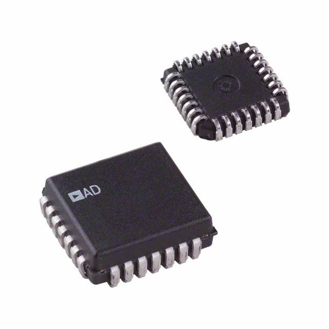
- Part No.:
- AD698APZ
- Manufacturer:
- Analog Devices Inc.
- Category:
- Sensor and Detector Interfaces
- Package:
- 28-LCC (J-Lead)
- Datasheet:
-
 AD698APZ.pdf
- Description:
- IC LVDT SIGNAL COND 28-PLCC
- Quantity:
- Payment:

- Shipping:

Inventory:2,477
Please send an inquiry. Send us your inquiry, and we will respond immediately.
Product details
Overview
AD698APZ from Analog Devices is a monolithic universal LVDT signal conditioner IC that converts mechanical core displacement into a high-accuracy DC output voltage via ratiometric synchronous demodulation. It integrates an oscillator (20 Hz–20 kHz), voltage reference, dual demodulation channels, and computational circuitry - requiring only passive external components for frequency, gain, and filtering. It supports half-bridge and 4-wire series-opposed LVDTs in industrial position sensing systems.
For engineers reviewing the AD698APZ datasheet, AD698APZ pinout, AD698APZ application, or AD698APZ equivalent, this page delivers verified technical context, exact pin functions, real-world linearity (±500 ppm), temperature-stable gain drift (20 ppm/°C), and validated alternatives for precision motion control, aerospace actuation, and test equipment design.
Technical Context
The AD698APZ implements a ratiometric architecture that computes the ratio of secondary-to-primary LVDT voltage (A/B) using duty-cycle multiplication, eliminating gain errors from oscillator amplitude drift. Its internal sine-wave oscillator (THD < –50 dB) drives the LVDT primary, while two independent synchronous demodulators process primary (B channel) and secondary (A channel) signals.
Phase compensation pins (+ACOMP/−ACOMP) allow correction of LVDT primary-to-secondary phase shift; filter pins (BFILT1/BFILT2, AFILT1/AFILT2) set bandwidth via external capacitors; and excitation amplitude is configured via resistor R1 between LEV1/LEV2. The device operates over –40°C to +85°C in its 40-lead LFCSP package.
Key Specifications
| Parameter | Value and Actual Design Meaning |
|---|---|
| Transfer Function | Ratiometric A/B division with 500 µA reference current - enables drift-free scaling independent of excitation amplitude |
| Nonlinearity | ±500 ppm of full scale - ensures sub-0.05% error across mechanical stroke without calibration |
| Output Voltage Range | ±11 V - supports direct interface to industrial PLC analog inputs and data acquisition systems |
| Gain Drift | 20 ppm/°C (typ) - guarantees stable sensitivity over wide ambient temperature swings in embedded systems |
| Excitation Frequency Range | 20 Hz to 20 kHz - accommodates low-frequency structural monitoring and high-speed servo feedback |
| Supply Voltage Range | ±13 V to ±18 V dual supply - compatible with standard industrial ±15 V rails |
| Operating Temperature | –40°C to +85°C - qualified for harsh industrial and avionics environments |
Pinout & Package
AD698APZ is housed in a 40-lead Lead Frame Chip Scale Package (LFCSP), thermally enhanced with exposed pad (unconnected per datasheet). Pin numbering follows JEDEC-standard 40-lead LFCSP layout (CP-40-7); θJA = 48.3°C/W under JEDEC 2S2P board conditions.
| Pin/Terminal | Circuit Role | Design Meaning |
|---|---|---|
| EXC1 / EXC2 | Oscillator differential output | Drives LVDT primary with low-distortion sine wave; frequency set by C1 on FREQ1/FREQ2 |
| LEV1 / LEV2 | Excitation amplitude control | Resistor R1 here sets RMS drive level (2.1–24 V) - critical for optimizing SNR and linearity |
| +AIN / −AIN | Secondary channel input | Connects to LVDT secondary winding; synchronous demodulation determines position polarity and magnitude |
| +BIN / −BIN | Primary channel monitor | Measures excitation voltage at LVDT primary - used as denominator in A/B ratio computation |
| SIG OUT | Analog output | DC voltage proportional to core displacement; scaled by R2 and referenced to SIG REF |
| FEEDBACK / OUTFILT | Output stability network | Capacitor C5 between these pins stabilizes output amplifier; R2 sets full-scale gain |
Key Features
| Feature | Design Value |
|---|---|
| No external adjustments required | Factory-trimmed ratiometric architecture eliminates potentiometers and field calibration for production repeatability |
| Half-bridge & 4-wire LVDT support | Configurable A/B channel routing enables use with both autotransformer-style and series-opposed transducers |
| Thermally protected excitation driver | Internal thermal shutdown prevents damage when driving multiple LVDTs in parallel or high-impedance loads |
| Phase compensation network | +ACOMP/−ACOMP pins allow RC networks to correct LVDT-induced phase lag, preserving null accuracy |
| Single capacitor frequency setting | FREQ1/FREQ2 accept one capacitor (C1) to set 20 Hz–20 kHz range - simplifies design vs. multi-component oscillators |
Applications
| Industrial Position Feedback | Aerospace Actuator Monitoring |
|---|---|
Use Scenario: Real-time measurement of hydraulic cylinder piston displacement in CNC machine tools and injection molding presses. IC Role / Device Role / Timing Role: LVDT signal conditioner converting mechanical stroke to calibrated ±10 V DC output for closed-loop motion control. Use Value: ±500 ppm nonlinearity and 20 ppm/°C gain drift ensure micron-level repeatability across 0–85°C factory environments without recalibration. |
Use Scenario: Core position sensing in flight control surface actuators (e.g., elevator, rudder) for fly-by-wire systems. IC Role / Device Role / Timing Role: High-reliability signal conditioning of redundant LVDTs with built-in thermal protection and ratiometric immunity to power supply ripple. Use Value: –40°C to +85°C operation and 4 kV HBM ESD rating meet DO-160 environmental stress requirements for airborne electronics. |
| Test & Measurement Equipment | Power Generation Control Systems |
Use Scenario: Precision displacement measurement in automated calibration benches for pressure transducers and force sensors. IC Role / Device Role / Timing Role: Universal LVDT interface supporting variable excitation frequencies (20 Hz–20 kHz) to match DUT resonance characteristics. Use Value: Single-capacitor frequency tuning and programmable offset (via OFFSET1/OFFSET2) accelerate setup time and reduce bench configuration complexity. |
Use Scenario: Turbine blade clearance monitoring and steam valve positioning in nuclear and fossil-fuel power plants. IC Role / Device Role / Timing Role: Ruggedized analog front-end providing fail-safe DC position output despite EMI-rich 50/60 Hz plant environments. Use Value: 100 ppm/dB excitation rejection and >50 dB PSRR suppress interference from nearby motor drives and switching power supplies. |
Equivalent & Alternatives
The following parts are listed as comparable options for similar LVDT signal conditioning applications.
| Alternative Part | Technical Difference | Application Difference | Selection Advice |
|---|---|---|---|
| AD598SD | Requires constant sum of secondary voltages (A+B); no phase compensation pins; 24-pin CERDIP only | Limited to traditional LVDTs with tight A+B tolerance; unsuitable for half-bridge or phase-shifted transducers | Select AD598SD only when legacy designs mandate pin compatibility with older AD598-based PCBs |
| PGA900IRHBT | Integrated 24-bit ADC, digital SPI interface, and diagnostics; requires external MCU; 32-pin QFN | Enables smart sensor functionality (self-test, temperature compensation, fault reporting) but adds firmware overhead | Choose PGA900IRHBT for new designs needing digital output, predictive maintenance, or IEC 61508 functional safety compliance |
Compared with AD698APZ, AD598SD lacks ratiometric flexibility and phase adjustment, limiting transducer compatibility; PGA900IRHBT adds intelligence and diagnostics but removes analog simplicity and increases BOM count - AD698APZ remains optimal for pure analog, high-accuracy, low-component-count LVDT interfaces.
Availability
AD698APZ is available at Aetrix Electronics and suitable for industrial position feedback, aerospace actuator monitoring, and test & measurement equipment requiring stable component supply, long-term lifecycle support, and traceable sourcing.
Supply support for AD698APZ includes scheduled delivery planning, volume procurement assistance, BOM continuity management, traceable sourcing, and lifecycle availability coordination for OEM customers, industrial embedded developers, connected-device designers, and electronics production programs.
Manufacturer
Analog Devices, Inc. is a global leader in high-performance analog, mixed-signal, and digital signal processing semiconductors, headquartered in Wilmington, MA.
The AD698 product line delivers monolithic LVDT signal conditioners optimized for precision motion sensing in harsh environments - designed to replace multi-chip discrete solutions with single-package reliability and ratiometric accuracy.
FAQ
What is the operating temperature range of the AD698APZ?
The AD698APZ is rated for operation from –40°C to +85°C, matching the industrial temperature grade specified in the Rev. D datasheet. This range is validated for the 40-lead LFCSP package (CP-40-7) and supports deployment in factory automation, outdoor test rigs, and avionics enclosures without derating. Thermal performance assumes proper PCB copper pour and thermal vias per JEDEC 2S2P guidelines.
Does the AD698APZ require external calibration or trimming components?
No, the AD698APZ requires no external adjustments or trimming components. Its ratiometric architecture, factory-trimmed internal reference, and matched demodulator channels eliminate the need for potentiometers or manual calibration. Linearity remains within ±500 ppm across temperature and supply variations - confirmed in Table 1 of the AD698 Rev. D datasheet.
Can the AD698APZ drive multiple LVDTs simultaneously?
Yes, the AD698APZ excitation outputs (EXC1/EXC2) can drive multiple LVDTs in parallel or series, provided total power dissipation stays within thermal limits. The datasheet explicitly states thermal protection on the excitation driver, and typical load capability is 30–50 mA rms. Designers must verify combined LVDT impedance and ensure peak excitation voltage remains within 2.1–24 V rms.
What is the purpose of the +ACOMP and −ACOMP pins on the AD698APZ?
The +ACOMP and −ACOMP pins on the AD698APZ provide access to the Channel A compensation circuit, enabling external RC networks to introduce phase lead or lag. This corrects LVDT-induced phase shifts between primary and secondary windings - critical for maintaining null accuracy and linearity, especially with long-cable installations or high-frequency excitation (>5 kHz).
How does the AD698APZ achieve immunity to excitation amplitude drift?
The AD698APZ achieves immunity by computing the ratio of secondary voltage (A) to primary voltage (B) using synchronous demodulation and duty-cycle multiplication. Since both A and B are derived from the same oscillator source, any amplitude drift affects numerator and denominator equally - canceling out in the A/B calculation. This ratiometric method is explicitly documented in the General Description and Theory of Operation sections of the AD698 Rev. D datasheet.
AD698APZ Specifications
- Product attributes
- Attribute value
- Manufacturer:
- Analog Devices Inc.
- Package/Case:
- 28-LCC (J-Lead)
- Series:
- -
- Packaging:
- Tube
- Product Status:
- Obsolete
- Programmable:
- Not Verified
- Type:
- Signal Conditioner
- Input Type:
- Voltage
- Output Type:
- Voltage
- Current - Supply:
- 15 mA
- Operating Temperature:
- -40°C ~ 85°C
- Grade:
- -
- Qualification:
- -
- Mounting Type:
- Surface Mount
- Supplier Device Package:
- 28-PLCC (11.51x11.51)
AD698APZ FAQ
1.How can I place an order for AD698APZ through Aetrix?
Please submit a Request for Quotation (RFQ) for AD698APZ on Aetrix. Our sales agent will provide a competitive quotation and guide you through the order confirmation once you accept the terms.
2.Are the price and stock information for AD698APZ reliable?
The price and inventory of AD698APZ are updated periodically and may fluctuate due to market conditions. Stock and pricing data are typically refreshed every 24 hours. Quotation validity for AD698APZ is usually 5 days.
3.What payment methods are accepted for AD698APZ?
We accept Wire Transfer, PayPal, Credit Card, Western Union, MoneyGram, and Escrow for AD698APZ transactions.
Note: Certain payment methods may incur a processing fee.
4.How is shipping managed for AD698APZ?
AD698APZ orders can be shipped via leading logistics carriers, including DHL, UPS, FedEx, TNT, or Registered Mail.
Once your AD698APZ order is processed, you will receive an email with the shipment details and tracking number.
Note: Tracking information may take up to 24 hours to appear. Express delivery typically takes 3–5 business days.
5.How can I obtain technical support or documentation for AD698APZ?
For technical support, including AD698APZ datasheets, pinout diagrams, or application guidance, please contact our engineering support team. They can provide detailed documentation and assistance for your AD698APZ requirements.
6.How does Aetrix verify that AD698APZ is sourced from the original manufacturer or authorized distributors?
All AD698APZ products on Aetrix are procured from qualified distributors and authorized channels. Our dedicated quality assurance team conducts strict verification, including traceability checks and, if necessary, third-party testing. This ensures that AD698APZ meets industry standards.
7.What is the process for return or replacement of AD698APZ?
All AD698APZ units undergo pre-shipment inspection (PSI). If there is an issue with AD698APZ, returns or replacements are accepted under the following conditions:
1.Quantity discrepancies, incorrect items, or visible external defects (such as breakage or corrosion), acknowledged by Aetrix.
2.The issue is reported within 90 days of delivery.
3.The AD698APZ part is unused and in its original packaging.
Return procedure for AD698APZ:
1.Submit a request within 90 days.
2.Obtain a Return Material Authorization (RMA) from Aetrix.
AD698APZ Tags

-
RE46C100S8TF
Microchip Technology

-
XTR111AIDRCR
Texas Instruments

-
XTR111AIDGQR
Texas Instruments

-
XTR117AIDGKR
Texas Instruments
-
XTR111AIDGQT
Texas Instruments

-
XTR115UA/2K5
Texas Instruments

-
MAX14626ETT+T
Analog Devices Inc./Maxim Integrated
-
XTR116UA/2K5
Texas Instruments
-
XTR115U/2K5
Texas Instruments
-
XTR116U/2K5
Texas Instruments

-
PGA308AIDGSR
Texas Instruments

-
XTR300AIRGWR
Texas Instruments
Tech Hub

A practical engineering guide to 3.3V and 5V logic compatibility, input thresholds, resistor dividers, translator ICs, MOSFET level shifting, I2C pull-ups, timing limits and power-sequencing risks.

The 74HC595 uses push-pull logic outputs, while the TPIC6B595 uses 50 V open-drain DMOS sinks for higher-power loads. This guide compares timing, current limits, 3.3 V interfacing, load wiring, thermal…

The 74HC595 converts serial data into eight stable parallel outputs. This guide covers pin functions, shift and storage timing, OE and MR behavior, drive-current limits, cascading, voltage compatibilit…

A technical comparison of level-sensitive latches and edge-triggered flip-flops, covering timing windows, setup and hold limits, master–slave operation, time borrowing, race-through, HDL inference and…

A D latch stores one bit while Enable controls when data can pass. This reference covers gate-level operation, truth tables, transparency, setup and hold timing, LE versus OE, common ICs and practical …

An SR latch stores one bit through cross-coupled feedback. This engineering reference covers NOR and NAND implementations, truth tables, forbidden-state recovery, gated operation, switch debouncing, fa…

Latch circuits retain one bit through feedback. This technical reference covers SR and D latches, truth tables, transparency, timing limits, latch-versus-flip-flop behavior, applications and common log…

An engineering guide to LED driver operation, constant-current and constant-voltage outputs, linear and switching topologies, dimming, IC selection, calculations, replacement compatibility, and fault c…

Operational amplifier guide covering op amp basics, feedback, ideal vs real op amps, common configurations, buffer circuits, offset, bias current, gain-bandwidth, slew rate, rail-to-rail limits and sel…

Jumper cables guide covering safe connection order, red and black clamp placement, final ground connection, cable gauge, length, clamp quality, copper vs CCA cables, jump starter comparison and battery…


