
 My Inquiry
 My Account


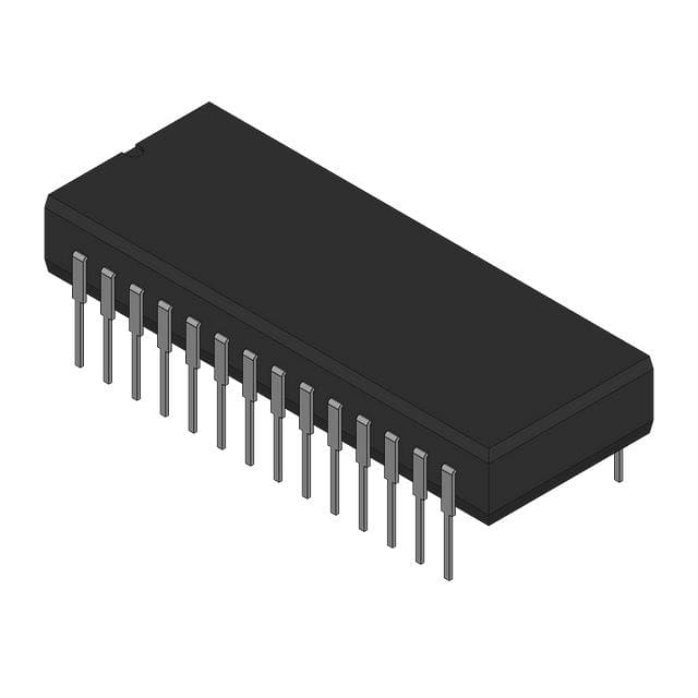
Analog Devices Inc. AD9002SD/883B
- Part No.:
- AD9002SD/883B
- Manufacturer:
- Analog Devices Inc.
- Category:
- Analog to Digital Converters (ADC)
- Package:
- 28-CDIP (0.600", 15.24mm)
- Datasheet:
-
 AD9002SD/883B.pdf
- Description:
- 8-BIT FLASH ADC, 8-BIT ACCESS
- Quantity:
- Payment:

- Shipping:

Inventory:1,528
Please send an inquiry. Send us your inquiry, and we will respond immediately.
Product details
Overview
AD9002SD/883B from Analog Devices is a military-grade, 8-bit monolithic analog-to-digital converter with 0.75 LSB differential linearity, 150 MSPS encode rate, and 160 MHz large-signal analog input bandwidth. It operates on a –5.2 V single supply, delivers 750 mW nominal power dissipation, and features ECL-compatible outputs with overflow indication-designed for radar warning receivers and electronic warfare signal acquisition.
For engineers reviewing the AD9002SD/883B datasheet, AD9002SD/883B pinout, AD9002SD/883B application, or AD9002SD/883B equivalent, this page provides verified technical context, MIL-STD-883B-compliant package details, real-world timing behavior (1.3 ns aperture delay, 15 ps jitter), and validated alternatives for high-speed sampling in extended-temperature defense systems.
Technical Context
The AD9002SD/883B implements a flash architecture with 256 parallel comparators and ECL-compatible output latches, enabling full 8-bit conversion on each rising edge of the differential ENCODE signal. Its comparator design incorporates user-adjustable hysteresis (0–10 mV via HYSTERESIS pin) and an overflow inhibit function to control overrange response polarity.
It uses a resistor ladder reference network with +VREF, –VREF, and REFMID pins, supporting 2.0 V differential reference voltage. Input bias current is 60–200 µA, input capacitance is 17 pF, and analog input slew rate is 440 V/µs-enabling direct sampling of fast pulses without external track-and-hold circuitry.
Key Specifications
| Parameter | Value and Actual Design Meaning |
|---|---|
| Resolution | 8-bit - delivers discrete quantization levels for digital signal processing of RF and pulse waveforms. |
| Encode Rate | 150 MSPS - supports real-time digitization of wideband signals up to Nyquist frequency of 75 MHz. |
| Differential Linearity | 0.75 LSB (max, full temperature range) - ensures monotonicity and minimizes code-width variation across all 256 codes. |
| Analog Input Bandwidth | 160 MHz - enables accurate capture of fast transients and high-frequency modulation without aliasing or settling error. |
| Aperture Uncertainty | 15 ps - limits sampling-time jitter-induced SNR degradation to ≤0.5 dB at 10 MHz input. |
| Power Dissipation | 750 mW at –5.2 V - compatible with conduction-cooled military chassis and thermally constrained embedded modules. |
| Operating Temperature | –55°C to +125°C - qualified per MIL-STD-883B Class B for airborne, missile, and ground vehicle electronics. |
Pinout & Package
AD9002SD/883B is packaged in a 28-lead side-brazed ceramic dual in-line package (SBDIP, D-28), hermetically sealed and qualified for military extended-temperature operation. The package features four digital ground pins, two analog ground pins, dual analog and digital –VS supply connections, and dedicated reference and hysteresis control terminals.
| Pin/Terminal | Circuit Role | Design Meaning |
|---|---|---|
| 1, 13, 20, 23 | DIGITAL GROUND | Low-impedance return path for ECL output switching currents; must be tied together and connected to system digital ground at single point near device. |
| 2 | OVERFLOW INH | Controls polarity of OVERFLOW output and data bus state during overrange inputs; logic low = non-return-to-zero mode, floating at –5.2 V = return-to-zero mode. |
| 3 | HYSTERESIS | Adjusts comparator hysteresis from 0 to 10 mV by applying –5.2 V to –2.2 V; improves noise immunity in high-EMI environments. |
| 4, 11, 12 | +VREF / –VREF / REFMID | Three-point reference interface for internal 40–110 Ω resistor ladder; enables precise offset and gain calibration and integral linearity correction. |
| 5, 10 | ANALOG INPUT | Differential analog input pair; requires matched trace lengths and symmetric drive to maintain <1.3 ns aperture delay matching. |
| 7, 8 | ENCODE / ENCODE | Differential ECL clock input; data latched on rising edge; requires <10 ns rise/fall time and proper termination to –2 V. |
| 15–19, 24–26 | D1(LSB) to D8(MSB) | ECL-compatible 8-bit parallel output bus; all outputs delayed by tPD (2.5–5.5 ns) and skewed ≤0.6 ns bit-to-bit. |
| 27 | OVERFLOW | Active-high flag indicating AIN > +VREF; asserted synchronously with data outputs and subject to same timing delays. |
Key Features
| Feature | Design Value |
|---|---|
| Flash ADC Architecture | 256 parallel comparators with fault-tolerant decoding logic eliminate missing codes and minimize false-code generation at 150 MSPS. |
| MIL-STD-883B Compliance | Class B screening includes temperature cycling, mechanical shock, vibration, and burn-in-ensuring reliability in mission-critical platforms. |
| Low Input Capacitance | 17 pF enables direct interface with wideband amplifiers (e.g., AD9610) without bandwidth-limiting external matching networks. |
| Overflow Control Logic | Dual-mode overrange handling (return-to-zero or non-return-to-zero) allows flexible data processing in pulse-detection and thresholding applications. |
| Adjustable Comparator Hysteresis | 0–10 mV programmable hysteresis via external voltage on HYSTERESIS pin improves dynamic performance in noisy RF front-end environments. |
Applications
| Radar Warning Receivers | Digital Oscilloscopes |
|---|---|
|
Use Scenario: Real-time detection and classification of pulsed RF threats across 2–18 GHz bands using superheterodyne downconversion and IF sampling. IC Role / Device Role / Timing Role: High-speed IF digitizer capturing 100+ MHz instantaneous bandwidth at 150 MSPS with sub-ns timing precision for pulse width and PRI measurement. Use Value: 160 MHz analog input bandwidth and 15 ps aperture jitter preserve pulse fidelity, enabling accurate emitter identification in dense signal environments. |
Use Scenario: Sampling of transient waveforms in benchtop and portable oscilloscopes requiring ≥100 MHz real-time bandwidth and deep memory capture. IC Role / Device Role / Timing Role: Primary ADC in acquisition front-end, synchronized to high-stability clock generator; outputs fed directly to FPGA-based decimation and display pipeline. Use Value: 0.75 LSB linearity and guaranteed no-missing-codes ensure waveform integrity across full dynamic range, critical for glitch capture and protocol analysis. |
| Electronic Warfare (ESM) | Laser Warning Systems |
|
Use Scenario: Wideband signal intelligence collection in airborne ESM pods, digitizing intermediate frequency outputs from channelized receivers. IC Role / Device Role / Timing Role: Digitizer for multi-channel IF streams; operates in –55°C to +125°C environment with minimal drift due to low offset drift coefficient (20 µV/°C). Use Value: Military-grade ceramic DIP packaging and MIL-STD-883B qualification ensure operational continuity under extreme thermal and mechanical stress. |
Use Scenario: Detection of short-duration laser pulses (nanosecond-scale) in vehicle-mounted countermeasure systems. IC Role / Device Role / Timing Role: Time-of-arrival digitizer sampling laser diode receiver outputs; uses overflow bit to flag saturation events during high-intensity exposure. Use Value: 440 V/µs input slew rate and 1.3 ns aperture delay enable precise pulse edge localization, improving angular accuracy of threat direction estimation. |
Equivalent & Alternatives
The following parts are listed as comparable options for similar high-speed sampling applications.
| Alternative Part | Technical Difference | Application Difference | Selection Advice |
|---|---|---|---|
| AD9002TD/883B | 0.5 LSB differential linearity vs. 0.75 LSB; otherwise identical electrical specs, package, and MIL-STD-883B qualification. | Suitable where tighter DC linearity is required for calibration-sensitive measurement systems, not just detection. | Select AD9002TD/883B only if system-level testing confirms 0.5 LSB is necessary; AD9002SD/883B offers lower cost and equal dynamic performance. |
| AD9042BRUZ | 12-bit, 41 MSPS, CMOS output, 3.3 V supply; no MIL-STD-883B option; 100 mA supply current vs. 175 mA. | Used in commercial test equipment and communications baseband where resolution > speed; lacks military temp range and ECL drive. | AD9002SD/883B remains mandatory for defense applications requiring extended temperature, radiation-hardened packaging, and ECL interfacing. |
Compared with AD9002TD/883B, AD9002SD/883B trades 0.25 LSB linearity for broader availability and lower unit cost while retaining identical timing, bandwidth, and environmental specs; versus AD9042BRUZ, it delivers 3.6× higher sample rate and military qualification at the expense of resolution and modern CMOS compatibility.
Availability
AD9002SD/883B is available at Aetrix Electronics and suitable for radar warning receivers, electronic warfare signal intelligence platforms, and laser warning systems requiring stable component supply across long production lifecycles and extreme environmental conditions.
Supply support for AD9002SD/883B includes scheduled delivery planning, volume procurement assistance, BOM continuity management, traceable sourcing, and lifecycle availability coordination for OEM customers, industrial embedded developers, connected-device designers, and electronics production programs.
Manufacturer
Analog Devices is a global leader in high-performance analog, mixed-signal, and digital signal processing semiconductors, serving aerospace, defense, industrial, and communications markets since 1965.
The AD9002 product line was engineered specifically for high-speed, wideband digitization in military and instrumentation applications-prioritizing sampling fidelity, thermal stability, and ruggedized packaging over consumer-grade integration or power efficiency.
FAQ
What is the maximum operating temperature range for the AD9002SD/883B?
The AD9002SD/883B is rated for continuous operation from –55°C to +125°C and is fully qualified per MIL-STD-883B Class B. This range is confirmed in the Ordering Guide and Absolute Maximum Ratings table, and applies to the ceramic DIP package used for this variant. The AD9002SD/883B maintains specified DC accuracy and dynamic performance across this full range without derating.
Does the AD9002SD/883B require external termination for its ECL outputs?
Yes, the AD9002SD/883B ECL outputs must be terminated to –2 V through 100 Ω resistors, as explicitly stated in the Electrical Characteristics table footnote 4 and Application Information section. Improper termination causes signal reflection, increased output skew (>0.6 ns), and degraded timing margins-especially critical at 150 MSPS operation.
How does the HYSTERESIS pin affect performance of the AD9002SD/883B?
The HYSTERESIS pin on the AD9002SD/883B adjusts comparator hysteresis from 0 mV to 10 mV by applying a voltage from –5.2 V to –2.2 V. This reduces sensitivity to noise-induced false triggering, particularly in high-EMI environments like radar front-ends. Data sheet Figure 4 and Functional Description confirm hysteresis directly modulates comparator decision thresholds without affecting linearity or encode timing.
Is the AD9002SD/883B pin-compatible with other AD9002 variants?
Yes, all AD9002 variants-including AD9002SD/883B, AD9002TD/883B, AD9002AD, and AD9002AJ-share identical 28-pin DIP or JLCC footprints and pin functions. The Pin Designations table and mechanical drawings confirm consistent pin numbering and signal mapping across grades. Only the linearity specification and temperature range differ between variants.
What is the purpose of the REFMID pin on the AD9002SD/883B?
The REFMID pin on the AD9002SD/883B provides access to the midpoint tap of the internal resistor ladder, enabling fine adjustment of reference symmetry to correct integral linearity errors caused by ladder mismatches. As described in Layout Suggestions and Functional Description, injecting a small trim voltage at REFMID improves INL without altering full-scale range or requiring external components.
AD9002SD/883B Specifications
- Product attributes
- Attribute value
- Manufacturer:
- Analog Devices Inc.
- Series:
- AD9002
- Package/Case:
- 28-CDIP (0.600", 15.24mm)
- Packaging:
- Bulk
- Product Status:
- Active
- Number of Bits:
- 8
- Sampling Rate (Per Second):
- 150M
- Number of Inputs:
- 1
- Input Type:
- -
- Data Interface:
- Parallel
- Configuration:
- ADC
- Ratio - S/H:ADC:
- 0:1
- Number of A/D Converters:
- 1
- Architecture:
- -
- Reference Type:
- External
- Voltage - Supply, Analog:
- -
- Voltage - Supply, Digital:
- -
- Features:
- -
- Operating Temperature:
- -55°C ~ 125°C
- Supplier Device Package:
- 28-CDIP
- Mounting Type:
- Through Hole
- Grade:
- -
- Qualification:
- -
AD9002SD/883B FAQ
1.How can I place an order for AD9002SD/883B through Aetrix?
Please submit a Request for Quotation (RFQ) for AD9002SD/883B on Aetrix. Our sales agent will provide a competitive quotation and guide you through the order confirmation once you accept the terms.
2.Are the price and stock information for AD9002SD/883B reliable?
The price and inventory of AD9002SD/883B are updated periodically and may fluctuate due to market conditions. Stock and pricing data are typically refreshed every 24 hours. Quotation validity for AD9002SD/883B is usually 5 days.
3.What payment methods are accepted for AD9002SD/883B?
We accept Wire Transfer, PayPal, Credit Card, Western Union, MoneyGram, and Escrow for AD9002SD/883B transactions.
Note: Certain payment methods may incur a processing fee.
4.How is shipping managed for AD9002SD/883B?
AD9002SD/883B orders can be shipped via leading logistics carriers, including DHL, UPS, FedEx, TNT, or Registered Mail.
Once your AD9002SD/883B order is processed, you will receive an email with the shipment details and tracking number.
Note: Tracking information may take up to 24 hours to appear. Express delivery typically takes 3–5 business days.
5.How can I obtain technical support or documentation for AD9002SD/883B?
For technical support, including AD9002SD/883B datasheets, pinout diagrams, or application guidance, please contact our engineering support team. They can provide detailed documentation and assistance for your AD9002SD/883B requirements.
6.How does Aetrix verify that AD9002SD/883B is sourced from the original manufacturer or authorized distributors?
All AD9002SD/883B products on Aetrix are procured from qualified distributors and authorized channels. Our dedicated quality assurance team conducts strict verification, including traceability checks and, if necessary, third-party testing. This ensures that AD9002SD/883B meets industry standards.
7.What is the process for return or replacement of AD9002SD/883B?
All AD9002SD/883B units undergo pre-shipment inspection (PSI). If there is an issue with AD9002SD/883B, returns or replacements are accepted under the following conditions:
1.Quantity discrepancies, incorrect items, or visible external defects (such as breakage or corrosion), acknowledged by Aetrix.
2.The issue is reported within 90 days of delivery.
3.The AD9002SD/883B part is unused and in its original packaging.
Return procedure for AD9002SD/883B:
1.Submit a request within 90 days.
2.Obtain a Return Material Authorization (RMA) from Aetrix.
AD9002SD/883B Tags
-
ADC081C021CIMKX/NOPB
Texas Instruments

-
MCP3021A5T-E/OT
Microchip Technology
-
TLA2024IRUGR
Texas Instruments
-
MCP3221A5T-E/OT
Microchip Technology
-
MCP3221A5T-I/OT
Microchip Technology
-
MCP3221A4T-E/OT
Microchip Technology
-
MCP3221A6T-E/OT
Microchip Technology
-
MCP3221A0T-E/OT
Microchip Technology
-
MCP3221A1T-E/OT
Microchip Technology

-
ADC121S021CIMFX/NOPB
Texas Instruments

-
MCP3001-I/MS
Microchip Technology

-
MCP3001-I/SN
Microchip Technology
Tech Hub

A practical engineering guide to 3.3V and 5V logic compatibility, input thresholds, resistor dividers, translator ICs, MOSFET level shifting, I2C pull-ups, timing limits and power-sequencing risks.

The 74HC595 uses push-pull logic outputs, while the TPIC6B595 uses 50 V open-drain DMOS sinks for higher-power loads. This guide compares timing, current limits, 3.3 V interfacing, load wiring, thermal…

The 74HC595 converts serial data into eight stable parallel outputs. This guide covers pin functions, shift and storage timing, OE and MR behavior, drive-current limits, cascading, voltage compatibilit…

A technical comparison of level-sensitive latches and edge-triggered flip-flops, covering timing windows, setup and hold limits, master–slave operation, time borrowing, race-through, HDL inference and…

A D latch stores one bit while Enable controls when data can pass. This reference covers gate-level operation, truth tables, transparency, setup and hold timing, LE versus OE, common ICs and practical …

An SR latch stores one bit through cross-coupled feedback. This engineering reference covers NOR and NAND implementations, truth tables, forbidden-state recovery, gated operation, switch debouncing, fa…

Latch circuits retain one bit through feedback. This technical reference covers SR and D latches, truth tables, transparency, timing limits, latch-versus-flip-flop behavior, applications and common log…

An engineering guide to LED driver operation, constant-current and constant-voltage outputs, linear and switching topologies, dimming, IC selection, calculations, replacement compatibility, and fault c…

Operational amplifier guide covering op amp basics, feedback, ideal vs real op amps, common configurations, buffer circuits, offset, bias current, gain-bandwidth, slew rate, rail-to-rail limits and sel…

Jumper cables guide covering safe connection order, red and black clamp placement, final ground connection, cable gauge, length, clamp quality, copper vs CCA cables, jump starter comparison and battery…


