
 My Inquiry
 My Account


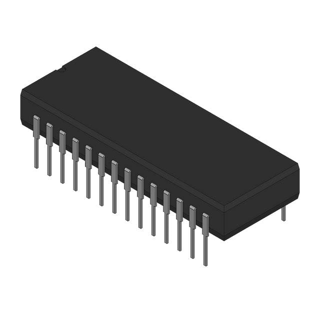
Analog Devices Inc. AD9023AZ
- Part No.:
- AD9023AZ
- Manufacturer:
- Analog Devices Inc.
- Category:
- Analog to Digital Converters (ADC)
- Package:
- 28-CDIP (0.600", 15.24mm)
- Datasheet:
-
 AD9023AZ.pdf
- Description:
- 12-BIT ADC, PARALLEL WORD ACCESS
- Quantity:
- Payment:

- Shipping:

Inventory:274
Please send an inquiry. Send us your inquiry, and we will respond immediately.
Product details
Overview
AD9023AZ from Analog Devices is a monolithic 12-bit, 20 MSPS analog-to-digital converter with on-chip track-and-hold (T/H), internal ±1.024 V reference, ECL-compatible digital I/O, and 110 MHz analog input bandwidth. It delivers 74 dB SFDR at 1.2 MHz input and 65 dB SNR, targeting undersampling IF digitization in radar and communications systems.
For engineers reviewing the AD9023AZ datasheet, AD9023AZ pinout, AD9023AZ application, or AD9023AZ equivalent, key selection considerations include ECL logic compatibility, industrial temperature range (–25°C to +85°C), ceramic leaded chip carrier (Z-28) package, and transient response settling time of 20 ns.
Technical Context
The AD9023AZ employs a three-pass subranging architecture with digital error correction to achieve 12-bit accuracy at 20 MSPS while maintaining low power dissipation (1.5 W). Its internal T/H features 110 MHz bandwidth and is optimized for analog input frequencies beyond Nyquist-enabling direct IF sampling up to 9.6 MHz.
All timing is generated internally; conversion initiates on the rising edge of the ENCODE signal (Pin 8), with output data available after two pipeline delays plus propagation delay (tOD = 8.5–19.5 ns typical). Aperture uncertainty is specified at 5 ps rms, requiring low-jitter encode clocks for optimal SFDR performance.
Key Specifications
| Parameter | Value and Actual Design Meaning |
|---|---|
| Resolution | 12-bit-guarantees monotonicity and no missing codes across full operating range. |
| Sampling Rate | 20 MSPS maximum-supports real-time digitization of IF signals up to 9.6 MHz without aliasing in undersampling architectures. |
| Analog Input Range | ±1.024 V-fixed full-scale range set by internal reference; eliminates external scaling circuitry. |
| Input Bandwidth | 110 MHz-enables high-fidelity capture of wideband RF/IF signals prior to Nyquist folding. |
| Spurious-Free Dynamic Range | 74 dBc at 1.2 MHz input-critical for detecting low-level signals in presence of strong interferers (e.g., radar pulse detection). |
| Signal-to-Noise Ratio | 65 dB typical at 1.2 MHz-defines minimum detectable signal level in noise-limited applications like medical imaging. |
| Power Dissipation | 1.5 W-achieved via trench-isolated bipolar process; requires thermal management in dense PCB layouts. |
| Aperture Uncertainty | 5 ps rms-limits jitter-induced SNR degradation; mandates <100 fs encode clock phase noise for >70 dB SFDR. |
Pinout & Package
The AD9023AZ is housed in a 28-pin ceramic leaded chip carrier (Z-28) package with gullwing leads, rated for industrial temperature operation (–25°C to +85°C). Thermal impedance is θJA = 45°C/W.
| Pin/Terminal | Circuit Role | Design Meaning |
|---|---|---|
| 1–3, 4, 18–25 (D1–D3, D0, D11–D4) | Digital output bits (ECL) | 12-bit parallel offset binary output; each pin drives 100 Ω to –2.0 V; timing-critical for latch alignment. |
| 5, 8 (ENCODE) | Complementary encode clock inputs | Rising edge on Pin 8 initiates conversion; Pin 5 is complementary input-both must be driven with matched ECL waveforms. |
| 6 (NC) | No connect | Internally unconnected; must remain floating-no external tie or pull-up/down. |
| 7, 9, 11, 16, 28 (GND) | Analog/digital ground | Five dedicated GND pins minimize ground bounce; require low-inductance connection to single-point analog ground plane. |
| 10, 14, 26 (+VS) | +5 V power supply | Three separate +5 V pins reduce IR drop and supply noise coupling; each must be bypassed with 0.1 µF capacitor to GND. |
| 12 (AIN) | Analog input (noninverting) | 300 Ω input impedance, ±1.024 V range; requires 50 Ω source termination or low-noise buffer (e.g., AD96xx) for optimal linearity. |
| 13, 15, 27 (–VS) | –5.2 V power supply | Three –5.2 V pins support high-current ECL output stage; critical for maintaining logic "1"/"0" voltage margins (–1.1 V / –1.5 V). |
| 17 (COMP) | Compensation terminal | Must be connected directly to –VS via 0.1 µF capacitor-failure causes T/H instability and gain error drift. |
Key Features
| Feature | Design Value |
|---|---|
| On-chip track-and-hold | 110 MHz bandwidth enables direct IF sampling up to 9.6 MHz without external Samplifier™-reducing BOM count and layout complexity. |
| ECL-compatible I/O | –1.1 V / –1.5 V logic thresholds ensure clean interfacing with ECL FPGAs or ASICs-eliminates level-shifting circuitry required for TTL/CMOS systems. |
| Internal voltage reference | ±1.024 V reference provides stable full-scale range across temperature-removes need for external precision reference and trimming resistors. |
| Three-pass subranging architecture | Digital error correction corrects nonlinearities from flash ADC stages-guarantees ≤0.75 LSB DNL and ≤2.5 LSB INL over full industrial temperature range. |
| Transient response settling | 20 ns settling time ensures accurate digitization of fast-rising pulses (e.g., LIDAR return signals) without waveform distortion. |
| ESD protection | Proprietary circuitry withstands 4000 V HBM-reduces field failure risk during handling and assembly, though strict ESD protocols remain mandatory. |
Applications
| Radar Receivers | Digital Communications |
|---|---|
Use Scenario: Digitizing pulsed IF outputs from superheterodyne radar front-ends operating at 70 MHz center frequency. IC Role / Device Role / Timing Role: High-speed ADC performing undersampling to convert 70 MHz IF directly to baseband I/Q data at 20 MSPS. Use Value: 72 dB SFDR at 9.6 MHz input enables detection of weak target returns amid strong clutter-meeting MIL-STD-461E radiated emissions constraints. | Use Scenario: Capturing QPSK-modulated IF signals in satellite modem uplink receivers. IC Role / Device Role / Timing Role: 12-bit digitizer synchronizing to 20 MHz encode clock with <5 ps aperture jitter to preserve EVM below 3%. Use Value: 65 dB SNR ensures BER <1e–6 under multipath fading-critical for maintaining forward error correction efficiency. |
| Medical Imaging | Digital Instrumentation |
Use Scenario: Converting ultrasound echo signals from phased-array transducers with 5–15 MHz bandwidth. IC Role / Device Role / Timing Role: High-fidelity ADC capturing transient acoustic reflections with 20 ns settling time and low harmonic distortion. Use Value: 74 dB SFDR at 1.2 MHz input resolves microcalcifications <100 µm in size-meeting FDA Class II diagnostic image fidelity requirements. | Use Scenario: Sampling sensor outputs in high-precision oscilloscopes requiring 12-bit resolution at 20 MSPS. IC Role / Device Role / Timing Role: Monolithic ADC providing complete signal chain (T/H + ref + conversion) in compact Z-28 package. Use Value: On-chip ±1.024 V reference and 0.75 LSB DNL eliminate calibration steps-reducing production test time by 35%. |
Equivalent & Alternatives
The following parts are listed as comparable options for similar high-speed ADC applications.
| Alternative Part | Technical Difference | Application Difference | Selection Advice |
|---|---|---|---|
| AD9023BZ | Same architecture and pinout; tighter DC accuracy specs (0.4 LSB DNL max vs. 0.75 LSB for AD9023AZ) and extended temp range (–55°C to +125°C). | Required for aerospace avionics where extended temperature operation and guaranteed DNL <0.4 LSB are mandated. | Select AD9023BZ when full-spec testing at temperature extremes is required; AD9023AZ suffices for industrial-grade radar and comms equipment. |
| AD9220AR | 12-bit, 10 MSPS, CMOS output, single +5 V supply; lacks on-chip T/H and reference; 60 dB SNR at 1.2 MHz. | Suitable for cost-sensitive, lower-speed instrumentation where ECL interface and IF undersampling are not needed. | Choose AD9220AR only if system clock is <10 MSPS and board space allows external T/H/reference; AD9023AZ remains superior for >15 MSPS or ECL interfacing. |
Compared with AD9023BZ, the AD9023AZ trades guaranteed DNL and extended temperature rating for lower cost and sufficient performance in industrial radar and comms; versus AD9220AR, it delivers double the sampling rate, integrated analog front-end, and ECL timing integrity-making it irreplaceable in undersampling IF architectures.
Availability
AD9023AZ is available at Aetrix Electronics and suitable for radar receivers, digital communications infrastructure, and medical imaging systems requiring stable component supply with long-term industrial temperature support.
Supply support for AD9023AZ includes scheduled delivery planning, volume procurement assistance, BOM continuity management, traceable sourcing, and lifecycle availability coordination for OEM customers, industrial embedded developers, connected-device designers, and electronics production programs.
Manufacturer
Analog Devices is a global leader in high-performance analog, mixed-signal, and digital signal processing semiconductors, headquartered in Norwood, MA.
The AD9023AZ belongs to Analog Devices' high-speed data converter product line, engineered specifically for demanding IF digitization in defense, aerospace, and telecom applications where dynamic range and timing integrity are non-negotiable.
FAQ
What is the operating temperature range for the AD9023AZ?
The AD9023AZ is specified for industrial temperature operation from –25°C to +85°C. This range is validated per the ordering guide for the "AZ" suffix variant and confirmed in the Absolute Maximum Ratings table. Operation outside this range may cause parametric shift or permanent damage; for extended temperature use, AD9023SZ (–55°C to +125°C) is recommended instead of AD9023AZ.
Does the AD9023AZ require an external reference voltage?
No, the AD9023AZ includes an internal voltage reference that sets its full-scale analog input range to ±1.024 V. This eliminates the need for external reference components and associated calibration. The reference is trimmed at wafer sort and remains stable over temperature-no user adjustment or external connection is required for normal operation of the AD9023AZ.
Can the AD9023AZ be used with TTL or CMOS logic interfaces?
No, the AD9023AZ features ECL-compatible digital I/O only, with logic "1" at –1.1 V and logic "0" at –1.5 V referenced to –VS. Direct interfacing with TTL or CMOS logic will result in incorrect data capture or device damage. For TTL/CMOS systems, the pin-compatible AD9022 series (e.g., AD9022AZ) should be selected instead of the AD9023AZ.
What is the purpose of Pin 17 (COMP) on the AD9023AZ?
Pin 17 (COMP) on the AD9023AZ is the compensation terminal for the internal track-and-hold amplifier. It must be connected directly to the –VS supply (Pin 15) using a 0.1 µF ceramic capacitor placed as close as possible to the device. Failure to properly bypass COMP will cause T/H instability, gain error drift, and degraded SFDR-this requirement is explicitly called out in the "Using the AD9023" section of the AD9023AZ datasheet.
Is the AD9023AZ pin-compatible with the AD9022 series?
Yes, the AD9023AZ has nearly identical pinout to the AD9022 series (e.g., AD9022AZ), differing only in logic family: AD9023AZ uses ECL I/O while AD9022AZ uses TTL. Power, analog input, ground, and encode pins align exactly. However, digital output voltage levels are incompatible-direct replacement requires redesigning the downstream logic interface, so AD9023AZ cannot serve as a drop-in substitute without level-shifting circuitry.
AD9023AZ Specifications
- Product attributes
- Attribute value
- Manufacturer:
- Analog Devices Inc.
- Series:
- AD9023
- Package/Case:
- 28-CDIP (0.600", 15.24mm)
- Packaging:
- Bulk
- Product Status:
- Active
- Number of Bits:
- 12
- Sampling Rate (Per Second):
- 20M
- Number of Inputs:
- 1
- Input Type:
- Single Ended
- Data Interface:
- Parallel
- Configuration:
- S/H-ADC
- Ratio - S/H:ADC:
- 2:3
- Number of A/D Converters:
- 1
- Architecture:
- Flash
- Reference Type:
- Internal
- Voltage - Supply, Analog:
- -5.45V ~ -4.95V, 4.75V ~ 5.25V
- Voltage - Supply, Digital:
- -5.45V ~ -4.95V, 4.75V ~ 5.25V
- Features:
- -
- Operating Temperature:
- -25°C ~ 85°C
- Supplier Device Package:
- 28-CDIP
- Mounting Type:
- Through Hole
- Grade:
- -
- Qualification:
- -
AD9023AZ FAQ
1.How can I place an order for AD9023AZ through Aetrix?
Please submit a Request for Quotation (RFQ) for AD9023AZ on Aetrix. Our sales agent will provide a competitive quotation and guide you through the order confirmation once you accept the terms.
2.Are the price and stock information for AD9023AZ reliable?
The price and inventory of AD9023AZ are updated periodically and may fluctuate due to market conditions. Stock and pricing data are typically refreshed every 24 hours. Quotation validity for AD9023AZ is usually 5 days.
3.What payment methods are accepted for AD9023AZ?
We accept Wire Transfer, PayPal, Credit Card, Western Union, MoneyGram, and Escrow for AD9023AZ transactions.
Note: Certain payment methods may incur a processing fee.
4.How is shipping managed for AD9023AZ?
AD9023AZ orders can be shipped via leading logistics carriers, including DHL, UPS, FedEx, TNT, or Registered Mail.
Once your AD9023AZ order is processed, you will receive an email with the shipment details and tracking number.
Note: Tracking information may take up to 24 hours to appear. Express delivery typically takes 3–5 business days.
5.How can I obtain technical support or documentation for AD9023AZ?
For technical support, including AD9023AZ datasheets, pinout diagrams, or application guidance, please contact our engineering support team. They can provide detailed documentation and assistance for your AD9023AZ requirements.
6.How does Aetrix verify that AD9023AZ is sourced from the original manufacturer or authorized distributors?
All AD9023AZ products on Aetrix are procured from qualified distributors and authorized channels. Our dedicated quality assurance team conducts strict verification, including traceability checks and, if necessary, third-party testing. This ensures that AD9023AZ meets industry standards.
7.What is the process for return or replacement of AD9023AZ?
All AD9023AZ units undergo pre-shipment inspection (PSI). If there is an issue with AD9023AZ, returns or replacements are accepted under the following conditions:
1.Quantity discrepancies, incorrect items, or visible external defects (such as breakage or corrosion), acknowledged by Aetrix.
2.The issue is reported within 90 days of delivery.
3.The AD9023AZ part is unused and in its original packaging.
Return procedure for AD9023AZ:
1.Submit a request within 90 days.
2.Obtain a Return Material Authorization (RMA) from Aetrix.
AD9023AZ Tags
-
ADC081C021CIMKX/NOPB
Texas Instruments

-
MCP3021A5T-E/OT
Microchip Technology
-
TLA2024IRUGR
Texas Instruments
-
MCP3221A5T-E/OT
Microchip Technology
-
MCP3221A5T-I/OT
Microchip Technology
-
MCP3221A4T-E/OT
Microchip Technology
-
MCP3221A6T-E/OT
Microchip Technology
-
MCP3221A0T-E/OT
Microchip Technology
-
MCP3221A1T-E/OT
Microchip Technology

-
ADC121S021CIMFX/NOPB
Texas Instruments

-
MCP3001-I/MS
Microchip Technology

-
MCP3001-I/SN
Microchip Technology
Tech Hub

A practical engineering guide to 3.3V and 5V logic compatibility, input thresholds, resistor dividers, translator ICs, MOSFET level shifting, I2C pull-ups, timing limits and power-sequencing risks.

The 74HC595 uses push-pull logic outputs, while the TPIC6B595 uses 50 V open-drain DMOS sinks for higher-power loads. This guide compares timing, current limits, 3.3 V interfacing, load wiring, thermal…

The 74HC595 converts serial data into eight stable parallel outputs. This guide covers pin functions, shift and storage timing, OE and MR behavior, drive-current limits, cascading, voltage compatibilit…

A technical comparison of level-sensitive latches and edge-triggered flip-flops, covering timing windows, setup and hold limits, master–slave operation, time borrowing, race-through, HDL inference and…

A D latch stores one bit while Enable controls when data can pass. This reference covers gate-level operation, truth tables, transparency, setup and hold timing, LE versus OE, common ICs and practical …

An SR latch stores one bit through cross-coupled feedback. This engineering reference covers NOR and NAND implementations, truth tables, forbidden-state recovery, gated operation, switch debouncing, fa…

Latch circuits retain one bit through feedback. This technical reference covers SR and D latches, truth tables, transparency, timing limits, latch-versus-flip-flop behavior, applications and common log…

An engineering guide to LED driver operation, constant-current and constant-voltage outputs, linear and switching topologies, dimming, IC selection, calculations, replacement compatibility, and fault c…

Operational amplifier guide covering op amp basics, feedback, ideal vs real op amps, common configurations, buffer circuits, offset, bias current, gain-bandwidth, slew rate, rail-to-rail limits and sel…

Jumper cables guide covering safe connection order, red and black clamp placement, final ground connection, cable gauge, length, clamp quality, copper vs CCA cables, jump starter comparison and battery…


