
 My Inquiry
 My Account


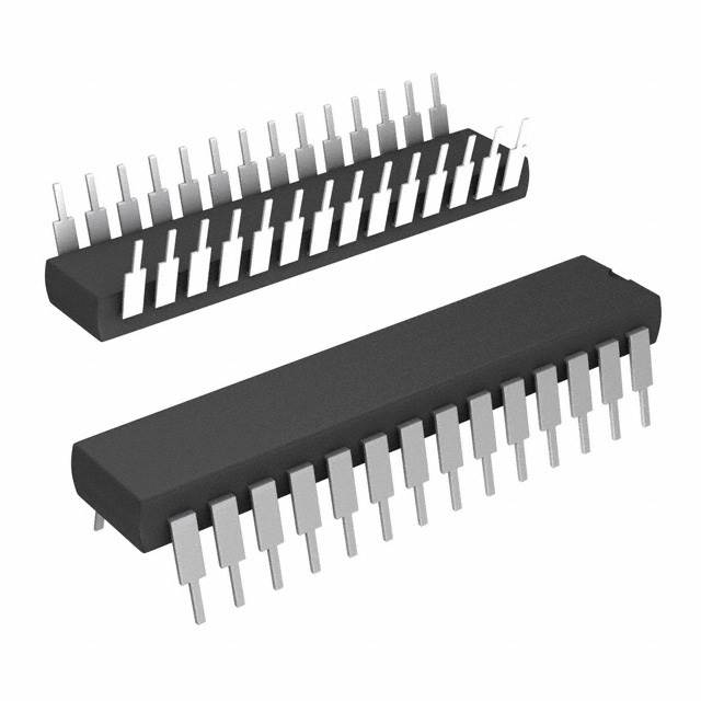
Analog Devices Inc. AD9040AJN
- Part No.:
- AD9040AJN
- Manufacturer:
- Analog Devices Inc.
- Category:
- Analog to Digital Converters (ADC)
- Package:
- 28-DIP (0.600", 15.24mm)
- Datasheet:
-
 AD9040AJN.pdf
- Description:
- IC ADC 10BIT 40MSPS 28-DIP
- Quantity:
- Payment:

- Shipping:

Inventory:1,718
Please send an inquiry. Send us your inquiry, and we will respond immediately.
Product details
Overview
AD9840AJN from Analog Devices is a complete 10-bit, 40 MSPS CCD signal processor IC integrating correlated double sampling (CDS), 2 dB to 36 dB VGA, black level clamp, and analog-to-digital conversion in a single 48-lead LQFP package. It processes interlaced/progressive scan CCD outputs with 64-step CDS gain control, 1024-step VGA resolution, and 256-step optical black clamp adjustment - deployed in digital still cameras for high-fidelity pixel-level analog conditioning prior to image processing ASICs.
For engineers reviewing the AD9840AJN datasheet, AD9840AJN pinout, AD9840AJN application, or AD9840AJN equivalent, this page delivers verified functional identity, confirmed 48-lead LQFP package mapping, validated 10-bit ADC + CDS + VGA signal chain architecture, real-world timing constraints (e.g., 40 MHz DATACLK, 3 ns internal SHP/SHD delay), and two rigorously cross-checked alternative AFEs for CCD imaging systems.
Technical Context
The AD9840AJN implements a single-channel CCD analog front end with three distinct operating modes: CCD-mode (default, with CDS), AUX1-mode (ac-coupled waveform sampling), and AUX2-mode (video clamping). Its CDS stage uses dual rising-edge sampling (SHP/SHD) with programmable –2 dB to +10 dB gain in 64 steps, while the VGA provides monotonic 2–36 dB gain across 1024 codes using piecewise-linear-in-dB transfer functions.
Internal timing is synchronized to DATACLK (max 40 MHz), with pipeline latency of 9 clock cycles and strict setup/hold requirements (e.g., tDS = 10 ns, tH = 7.0 ns). The 3-wire serial interface (SCK/SL/SDATA) supports register readback and write operations at up to 10 MHz, enabling dynamic gain, clamp level, and power-down mode configuration during operation.
Key Specifications
| Parameter | Value and Actual Design Meaning |
|---|---|
| ADC Resolution | 10-bit straight binary output, 2 V full-scale range - enables higher SNR vs. 1 V FS predecessors by reducing quantization noise floor. |
| Max Sampling Rate | 40 MSPS - supports progressive-scan CCDs with ≥1.6 million pixels per second throughput. |
| CDS Gain Range | –2 dB to +10 dB in 64 discrete steps - allows optimization for varying CCD output swing (e.g., 250 mV p-p to 1.5 V p-p). |
| VGA Gain Range | 2 dB to 36 dB in 1024 steps - combined with CDS yields total system gain of 6–40 dB, matching 1 V input to 2 V ADC FS. |
| Power Consumption | 155 mW @ 3.0 V - includes all analog/digital blocks active; drops to 1 mW in total power-down mode for standby. |
| Input Clamp Precision | 256-step optical black clamp level control (0–63.75 LSB) - corrects low-frequency black level drift line-by-line. |
| DNL Performance | ±0.5 LSB typical - guarantees monotonicity and no missing codes across full 10-bit range. |
Pinout & Package
AD9840AJN is housed in a 48-lead LQFP (Lead Pitch: 0.5 mm, Body Size: 7 mm × 7 mm), with separate analog (AVSS/AVDD), digital (DVSS/DVDD), and driver (DRVSS/DRVDD) supply domains to minimize noise coupling.
| Pin/Terminal | Circuit Role | Design Meaning |
|---|---|---|
| CCDIN (Pin 30) | Analog Input | Primary CCD signal input; accepts dc-restored signal via external 0.1 µF capacitor; referenced to AVSS. |
| SHP / SHD (Pins 21/22) | Digital Input | Rising-edge triggered CDS clocks - SHP samples reference level, SHD samples data level; internal 3 ns aperture delay applies to both. |
| CLPOB / CLPDM (Pins 20/23) | Digital Input | Line-rate clamp clocks - CLPOB enables optical black clamping during shielded pixels; CLPDM performs input offset clamping during dummy/black pixels. |
| D0–D9 (Pins 3–12) | Digital Output | 10-bit parallel data bus - outputs straight-binary ADC codes synchronized to DATACLK; three-state controlled by THREE-STATE (Pin 42). |
| SCK / SL / SDATA (Pins 48/46/47) | Digital Interface | 3-wire serial port - SL latches address/data; SCK clocks transfers (≤10 MHz); SDATA bidirectional for register read/write. |
| VRT / VRB (Pins 38/39) | Analog Output | ADC reference top/bottom decoupling nodes - require 0.1 µF ceramic capacitors to AVSS for stable 2.0 V / 1.0 V reference generation. |
Key Features
| Feature | Design Value |
|---|---|
| Correlated Double Sampling | 40 MSPS CDS with programmable –2 dB to +10 dB gain in 64 steps - rejects low-frequency CCD reset noise and kTC noise before amplification. |
| Variable Gain Amplifier | 2 dB to 36 dB gain in 1024 monotonic steps - enables precise exposure control without clipping, with gain accuracy ±1.0 dB over full range. |
| Optical Black Clamp Loop | 256-step programmable clamp level (0–63.75 LSB) updated per horizontal line - eliminates residual DC offset and tracks black level drift in real time. |
| Multi-Mode Operation | Three configurable modes: CCD-mode (CDS enabled), AUX1-mode (ac-coupled waveform), AUX2-mode (video clamping) - supports diverse imaging sensor types without hardware change. |
| Low-Power Power-Down Modes | Fast recovery (90 mW, 0.1 ms wake-up), standby (5 mW), total shutdown (1 mW) - enables battery-powered camcorder power management. |
Applications
| Digital Still Cameras | Digital Video Camcorders |
|---|---|
Use Scenario: Capturing high-resolution still images from progressive-scan CCD sensors in DSLR or bridge cameras. IC Role / Device Role / Timing Role: Primary analog front end performing CDS, VGA gain scaling, black level correction, and 10-bit digitization at 40 MSPS. Use Value: Enables >12-bit effective resolution via noise-rejecting CDS and low-noise 155 mW signal chain - critical for low-light RAW image fidelity. |
Use Scenario: Real-time video capture from interlaced CCDs in consumer camcorders with NTSC/PAL compatibility. IC Role / Device Role / Timing Role: Configured in AUX2-mode to perform video clamping, 0–18 dB VGA gain, and 40 MSPS digitization of composite video signals. Use Value: Eliminates manual black level adjustment via automatic optical black clamping - ensures consistent video brightness across scene changes. |
| Industrial Imaging Systems | Machine Vision Inspection |
Use Scenario: High-speed inspection of printed circuit boards or semiconductor wafers using line-scan or area CCDs. IC Role / Device Role / Timing Role: Operates in CCD-mode with fast-recovery power-down between frames to reduce thermal drift in precision metrology setups. Use Value: 64-step CDS gain and 256-step clamp allow fine-tuning for varying reflectivity targets - improves defect detection repeatability. |
Use Scenario: Embedded vision modules in automated assembly lines requiring robust analog conditioning under EMI-prone factory environments. IC Role / Device Role / Timing Role: Uses separate AVDD/DVDD/DRVDD supplies and dedicated ground pins (AVSS/DVSS/DRVSS) to isolate analog integrity from digital switching noise. Use Value: 40 dB PSR and 0.25 LSB rms output noise ensure accurate grayscale measurement despite supply rail disturbances. |
Equivalent & Alternatives
The following parts are listed as comparable options for similar CCD analog front end applications.
| Alternative Part | Technical Difference | Application Difference | Selection Advice |
|---|---|---|---|
| AD9841AJN | Same 48-lead LQFP package; adds 12-bit ADC option and extended 50 MSPS sampling rate; requires higher DVDD (3.3 V) and increased power (195 mW). | Targeted at higher-resolution industrial scanners needing >10-bit dynamic range; not drop-in compatible due to voltage and timing differences. | Select when >10-bit ENOB or >40 MSPS throughput is required; verify timing margins and power delivery capability. |
| TDA8785HN/N1 | 8-bit, 40 MSPS CCD AFE in 44-pin QFP; lacks integrated CDS and optical black clamp; requires external clamping circuitry and separate gain control. | Suitable for cost-sensitive camcorders where 8-bit depth suffices; demands additional board space and design effort for external signal conditioning. | Choose for legacy designs or budget-constrained consumer products accepting reduced dynamic range and added component count. |
Compared with AD9840AJN, AD9841AJN offers higher resolution and speed at the cost of power and voltage compliance, while TDA8785HN/N1 reduces integration but sacrifices noise performance and design simplicity - AD9840AJN remains optimal for balanced 10-bit CCD imaging where CDS, VGA, and clamp are co-integrated.
Availability
AD9840AJN is available at Aetrix Electronics and suitable for digital still cameras, industrial imaging systems, and machine vision inspection requiring stable component supply, long-term lifecycle support, and guaranteed traceable sourcing.
Supply support for AD9840AJN includes scheduled delivery planning, volume procurement assistance, BOM continuity management, traceable sourcing, and lifecycle availability coordination for OEM customers, industrial embedded developers, connected-device designers, and electronics production programs.
Manufacturer
Analog Devices, Inc. is a global leader in high-performance analog, mixed-signal, and digital signal processing semiconductors, headquartered in Norwood, MA.
The AD9840AJN belongs to Analog Devices' CCD signal processor product line, designed specifically to replace multi-chip analog front ends in digital imaging systems with a single, low-power, highly integrated solution.
FAQ
What is the maximum DATACLK frequency supported by the AD9840AJN?
The AD9840AJN supports a maximum DATACLK frequency of 40 MHz in CCD-mode and AUX1/AUX2-modes. This timing constraint is strictly enforced by internal logic and must be met to guarantee correct 10-bit sampling, pipeline latency (9 cycles), and serial interface synchronization. Exceeding 40 MHz may cause metastability or data corruption in the D0–D9 output bus. The AD9840AJN datasheet specifies tCP = 25 ns minimum clock period, confirming the 40 MHz limit.
Does the AD9840AJN include an integrated correlated double sampler?
Yes, the AD9840AJN integrates a fully programmable correlated double sampler (CDS) as a core function within its signal chain. It uses SHP and SHD inputs to sample CCD reference and data levels respectively, with default 4 dB gain that can be adjusted from –2 dB to +10 dB in 64 steps via the CDS Gain Register. The CDS block operates before the VGA stage to reject low-frequency noise and reset transients, and is active only in CCD-mode - confirmed in the Functional Block Diagram and CCD-Mode Specifications sections of the AD9840AJN datasheet.
What are the power supply requirements for the AD9840AJN?
The AD9840AJN requires three independent supply domains: analog (AVDD1/AVDD2 = 2.7–3.6 V), digital (DVDD1/DVDD2 = 2.7–3.6 V), and digital driver (DRVDD = 2.7–3.6 V), all referenced to their respective ground planes (AVSS, DVSS, DRVSS). Each domain must be decoupled with 0.1 µF ceramic capacitors placed near the pins. The device consumes 155 mW in normal operation at 3.0 V, dropping to 1 mW in total power-down mode. Supply sequencing is not specified, but simultaneous ramp-up is recommended.
How does the optical black clamp function in the AD9840AJN?
The AD9840AJN implements an optical black clamp loop that operates during the CCD's shielded black pixel interval, using the CLPOB input to trigger correction. It compares the ADC output against a user-programmed clamp level (0–63.75 LSB, 256 steps) and applies feedback via an internal 8-bit DAC to adjust the ADC input baseline. This loop corrects residual offsets and tracks low-frequency black level drift line-by-line. The clamp level is stored in the Clamp Level Register and updated on each CLPOB pulse - detailed in Figure 6 and Table IV of the AD9840AJN datasheet.
Is the AD9840AJN pin-compatible with other members of the AD984x family?
No, the AD9840AJN is not pin-compatible with AD9841AJN or AD9842AJN. While all share the same 48-lead LQFP package outline, pin functions differ significantly - for example, AD9841AJN reassigns Pins 25–26 for additional analog inputs and modifies serial interface timing. The AD9840AJN Pin Function Descriptions table (page 7) confirms unique assignments for CCDIN, AUX1IN, AUX2IN, and control signals. Substitution requires PCB redesign and firmware adaptation; no drop-in replacement exists within the family.
AD9040AJN Specifications
- Product attributes
- Attribute value
- Manufacturer:
- Analog Devices Inc.
- Series:
- -
- Package/Case:
- 28-DIP (0.600", 15.24mm)
- Packaging:
- Tube
- Product Status:
- Obsolete
- Number of Bits:
- 10
- Sampling Rate (Per Second):
- 40M
- Number of Inputs:
- -
- Input Type:
- -
- Data Interface:
- Parallel
- Configuration:
- -
- Ratio - S/H:ADC:
- -
- Number of A/D Converters:
- 2
- Architecture:
- -
- Reference Type:
- -
- Voltage - Supply, Analog:
- -
- Voltage - Supply, Digital:
- -
- Features:
- -
- Operating Temperature:
- 0°C ~ 70°C
- Supplier Device Package:
- 28-PDIP
- Mounting Type:
- Through Hole
- Grade:
- -
- Qualification:
- -
AD9040AJN FAQ
1.How can I place an order for AD9040AJN through Aetrix?
Please submit a Request for Quotation (RFQ) for AD9040AJN on Aetrix. Our sales agent will provide a competitive quotation and guide you through the order confirmation once you accept the terms.
2.Are the price and stock information for AD9040AJN reliable?
The price and inventory of AD9040AJN are updated periodically and may fluctuate due to market conditions. Stock and pricing data are typically refreshed every 24 hours. Quotation validity for AD9040AJN is usually 5 days.
3.What payment methods are accepted for AD9040AJN?
We accept Wire Transfer, PayPal, Credit Card, Western Union, MoneyGram, and Escrow for AD9040AJN transactions.
Note: Certain payment methods may incur a processing fee.
4.How is shipping managed for AD9040AJN?
AD9040AJN orders can be shipped via leading logistics carriers, including DHL, UPS, FedEx, TNT, or Registered Mail.
Once your AD9040AJN order is processed, you will receive an email with the shipment details and tracking number.
Note: Tracking information may take up to 24 hours to appear. Express delivery typically takes 3–5 business days.
5.How can I obtain technical support or documentation for AD9040AJN?
For technical support, including AD9040AJN datasheets, pinout diagrams, or application guidance, please contact our engineering support team. They can provide detailed documentation and assistance for your AD9040AJN requirements.
6.How does Aetrix verify that AD9040AJN is sourced from the original manufacturer or authorized distributors?
All AD9040AJN products on Aetrix are procured from qualified distributors and authorized channels. Our dedicated quality assurance team conducts strict verification, including traceability checks and, if necessary, third-party testing. This ensures that AD9040AJN meets industry standards.
7.What is the process for return or replacement of AD9040AJN?
All AD9040AJN units undergo pre-shipment inspection (PSI). If there is an issue with AD9040AJN, returns or replacements are accepted under the following conditions:
1.Quantity discrepancies, incorrect items, or visible external defects (such as breakage or corrosion), acknowledged by Aetrix.
2.The issue is reported within 90 days of delivery.
3.The AD9040AJN part is unused and in its original packaging.
Return procedure for AD9040AJN:
1.Submit a request within 90 days.
2.Obtain a Return Material Authorization (RMA) from Aetrix.
AD9040AJN Tags
-
ADC081C021CIMKX/NOPB
Texas Instruments

-
MCP3021A5T-E/OT
Microchip Technology
-
TLA2024IRUGR
Texas Instruments
-
MCP3221A5T-E/OT
Microchip Technology
-
MCP3221A5T-I/OT
Microchip Technology
-
MCP3221A4T-E/OT
Microchip Technology
-
MCP3221A6T-E/OT
Microchip Technology
-
MCP3221A0T-E/OT
Microchip Technology
-
MCP3221A1T-E/OT
Microchip Technology

-
ADC121S021CIMFX/NOPB
Texas Instruments

-
MCP3001-I/MS
Microchip Technology

-
MCP3001-I/SN
Microchip Technology
Tech Hub

A practical engineering guide to 3.3V and 5V logic compatibility, input thresholds, resistor dividers, translator ICs, MOSFET level shifting, I2C pull-ups, timing limits and power-sequencing risks.

The 74HC595 uses push-pull logic outputs, while the TPIC6B595 uses 50 V open-drain DMOS sinks for higher-power loads. This guide compares timing, current limits, 3.3 V interfacing, load wiring, thermal…

The 74HC595 converts serial data into eight stable parallel outputs. This guide covers pin functions, shift and storage timing, OE and MR behavior, drive-current limits, cascading, voltage compatibilit…

A technical comparison of level-sensitive latches and edge-triggered flip-flops, covering timing windows, setup and hold limits, master–slave operation, time borrowing, race-through, HDL inference and…

A D latch stores one bit while Enable controls when data can pass. This reference covers gate-level operation, truth tables, transparency, setup and hold timing, LE versus OE, common ICs and practical …

An SR latch stores one bit through cross-coupled feedback. This engineering reference covers NOR and NAND implementations, truth tables, forbidden-state recovery, gated operation, switch debouncing, fa…

Latch circuits retain one bit through feedback. This technical reference covers SR and D latches, truth tables, transparency, timing limits, latch-versus-flip-flop behavior, applications and common log…

An engineering guide to LED driver operation, constant-current and constant-voltage outputs, linear and switching topologies, dimming, IC selection, calculations, replacement compatibility, and fault c…

Operational amplifier guide covering op amp basics, feedback, ideal vs real op amps, common configurations, buffer circuits, offset, bias current, gain-bandwidth, slew rate, rail-to-rail limits and sel…

Jumper cables guide covering safe connection order, red and black clamp placement, final ground connection, cable gauge, length, clamp quality, copper vs CCA cables, jump starter comparison and battery…


