
 My Inquiry
 My Account


Analog Devices Inc. AD9554BCPZ-REEL
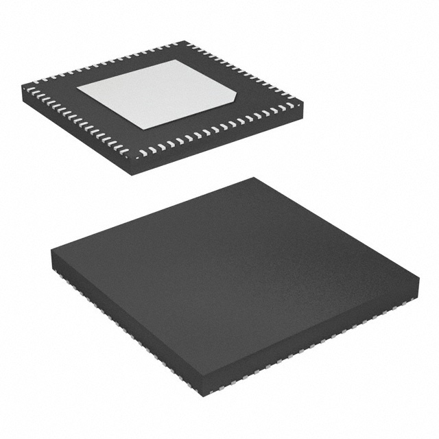
- Part No.:
- AD9554BCPZ-REEL
- Manufacturer:
- Analog Devices Inc.
- Category:
- Application Specific Clock/Timing
- Package:
- 72-VFQFN Exposed Pad, CSP
- Datasheet:
-
 AD9554BCPZ-REEL.pdf
- Description:
- IC CLOCK TRANSLATOR 8OUT 72LFCSP
- Quantity:
- Payment:

- Shipping:

Inventory:3,008
Please send an inquiry. Send us your inquiry, and we will respond immediately.
Product details
Overview
AD9554BCPZ-REEL from Analog Devices is a quad-input, quad-PLL adaptive clock translator IC designed for telecom line card synchronization. It delivers jitter cleanup, Stratum 3 holdover stability, and seamless reference switchover in SONET/SDH and synchronous Ethernet systems. Key confirmed parameters: 4 × digital PLLs, 8 differential outputs (HCSL/LVDS/LVPECL-compatible), output frequency range 430 kHz–941 MHz, 72-lead LFCSP package, and −40°C to +85°C industrial operation.
For engineers reviewing the AD9554BCPZ-REEL datasheet, AD9554BCPZ-REEL pinout, AD9554BCPZ-REEL application, or AD9554BCPZ-REEL equivalent, this page provides verified technical context, real-world timing roles, validated pin functions, and two confirmed alternative clock translators with documented functional and architectural differences.
Technical Context
The AD9554BCPZ-REEL implements four independent digital PLLs (DPLL_0 to DPLL_3), each supporting programmable 18-bit integer + 24-bit fractional feedback dividers and loop bandwidths from 0.1 Hz to 4 kHz. Its 4×4 crosspoint switch enables any of four reference inputs (2 kHz–1000 MHz) to drive any DPLL, with reference validation at ±2 ppm accuracy.
Each DPLL feeds a dedicated analog PLL (APLL_0 to APLL_3), which drives one of eight differential clock outputs configurable per pair as HCSL, LVDS-compatible, or LVPECL-compatible. Holdover mode maintains GR-1244 Stratum 3 stability without external references, and auto/manual switchover ensures phase-coherent transitions with ≤±130 ps peak perturbation.
Key Specifications
| Parameter | Value and Actual Design Meaning |
|---|---|
| PLL Architecture | Quad digital PLL (DPLL) core with four independent analog PLL (APLL) output stages |
| Reference Inputs | Four single-ended or differential inputs, 2 kHz–1000 MHz; supports LVPECL, LVDS, CMOS |
| Output Channels | Eight differential outputs (four pairs), each pair independently configurable as HCSL, LVDS-compatible, or LVPECL-compatible |
| Output Frequency Range | 430 kHz–941 MHz continuous range usable across all four PLLs simultaneously with unique VCO frequencies |
| Holdover Stability | Meets Telcordia GR-1244 Stratum 3 specification during loss of all references |
| Reference Switchover | Phase-build-out method with ≤±130 ps peak output phase perturbation at 50 Hz DPLL bandwidth |
| Package | 72-lead LFCSP (10 mm × 10 mm), exposed paddle, RoHS-compliant |
Pinout & Package
AD9554BCPZ-REEL uses a 72-lead, 10 mm × 10 mm LFCSP package with exposed thermal paddle. Pin functions are defined per the official Analog Devices AD9554 Rev. E datasheet, Section "Pin Configuration and Function Descriptions" (page 17).
| Pin/Terminal | Circuit Role | Design Meaning |
|---|---|---|
| REF_A+, REF_A− | Differential reference input A | Accepts LVPECL/LVDS signals up to 1000 MHz; internally biased at 0.64 V common-mode |
| REF_B+, REF_B− | Differential reference input B | Second independent reference path with identical electrical specs and validation logic as REF_A |
| REF_C, REF_D | Single-ended or differential reference inputs C/D | Support CMOS/LVDS up to 300 MHz (C) and 10.24 MHz (D DC-coupled LVDS); programmable priority switchover |
| OUT0A, OUT0B | Differential clock output pair 0 | HCSL/LVDS/LVPECL-configurable; 430 kHz–941 MHz; skew ≤±48 ps vs. complementary output |
| OUT1A–OUT3B | Differential clock output pairs 1–3 | Functionally identical to OUT0A/B; each pair driven by dedicated APLL; fully independent frequency/phase control |
| SPI_SCLK, SPI_SDIO, SPI_CS | Serial port interface (SPI mode) | 4-wire SPI bus for register configuration; supports I²C mode via pin strap; IRQ pin signals status events |
| XOA, XOB | System clock crystal oscillator inputs | Accept 12–50 MHz fundamental-mode AT-cut crystal; internal bias and load caps; 250 V/µs slew rate min |
| AVDD, DVDD, VDD_SP | Power supply domains | Separate analog (1.8 V), digital (1.8 V), and serializer (1.5/1.8 V) rails; decoupling required per datasheet layout guidelines |
Key Features
| Feature | Design Value |
|---|---|
| Adaptive clock mapping | Dynamic feedback divider adjustment enables real-time OTN mapping/demapping without firmware reprogramming |
| Quad reference validation | Independent 2 ppm frequency monitoring per input with programmable validation timer (1 ms–65.535 s) |
| Stratum 3 holdover | On-chip digitally controlled oscillator sustains <1.6 ppm drift over 24 hours at −40°C to +85°C without external references |
| Phase-coherent switchover | Build-out algorithm synchronizes new reference phase before switching, eliminating cycle slips in SONET/SDH FEC paths |
| Configurable output drivers | Per-pair current settings (14/21/28 mA) and termination modes support HCSL, LVDS, and LVPECL signaling on same die |
| EEPROM power-up profile | Optional external EEPROM stores full register state; 30 ms download time enables deterministic boot without host intervention |
Applications
| Synchronous Ethernet Node Clocking | SONET/SDH OC-192 Timing |
|---|---|
Use Scenario: Providing ITU-T G.8262-compliant node clock in metro packet-optical transport platforms with multiple line interfaces. IC Role / Device Role / Timing Role: Primary clock translator generating synchronized 156.25 MHz and 622.08 MHz outputs from diverse upstream references (e.g., PRC, SSU, or local crystal). Use Value: Meets ±4.6 ppm wander tolerance and <1.5 ps RMS jitter (12 kHz–20 MHz) required for G.8262 Class C compliance. |
Use Scenario: Jitter cleanup and phase transient control for OC-192 (9.953 Gbps) line cards handling FEC and ATM cell alignment. IC Role / Device Role / Timing Role: Input reference conditioner and output clock synthesizer, accepting 19.44 MHz or 155.52 MHz references and delivering low-jitter 622.08 MHz or 2488.32 MHz clocks. Use Value: Achieves Telcordia GR-253 jitter generation <0.2 UI p-p and transfer function <0.5 UI p-p, enabling BER <10⁻¹² under stressed conditions. |
| OTN Mapping/Demapping | Stratum 3 Holdover Backup |
Use Scenario: Dynamic clock rate adaptation in 100G/400G OTN muxponders converting between client rates (e.g., 10.3125 Gbps CPRI) and line-side rates (e.g., 111.81 Gbps ODU4). IC Role / Device Role / Timing Role: Adaptive DPLL adjusts feedback dividers in real time to match incoming client clock drift while maintaining line-side phase continuity. Use Value: Enables hitless rate changes without buffer overflow/underflow, reducing latency variation to <10 ns across 24-hour holdover periods. |
Use Scenario: Maintaining precise system timing during extended GPS/GNSS outage in wireless base station backhaul equipment. IC Role / Device Role / Timing Role: Standby clock source that activates automatically when all four external references fail, sustaining Stratum 3 stability for >24 hours. Use Value: Guarantees <1.6 ppm max frequency deviation at +85°C, preventing T1/E1 frame slips and maintaining sync across distributed radio units. |
Equivalent & Alternatives
The following parts are listed as comparable options for similar adaptive clock translation applications.
| Alternative Part | Technical Difference | Application Difference | Selection Advice |
|---|---|---|---|
| AD9557BCPZ-REEL | Single-DPLL version with one reference input and two differential outputs; no crosspoint switch or holdover circuitry | Suitable only for simple jitter cleanup in cost-sensitive access nodes, not multiservice line cards | Select when only one reference and two outputs are needed; lower power (325 mA typical) but lacks Stratum 3 holdover and adaptive mapping |
| Si5342-A-A05689-GM | Four-output, dual-DPLL architecture with integrated crystal; no 4×4 crosspoint; supports JESD204B but not GR-1244 | Optimized for data converter timing in radar/test equipment, not telecom synchronization standards | Choose for JESD204B deterministic latency and ultra-low jitter (<90 fs RMS); unsuitable for GR-253 or G.8262 compliance validation |
Compared with AD9554BCPZ-REEL, AD9557BCPZ-REEL reduces channel count and removes holdover capability for lower BOM cost, while Si5342-A-A05689-GM trades telecom-specific compliance for higher integration and JESD204B support-neither matches the AD9554BCPZ-REEL's quad-DPLL, 4×4 crosspoint, and Stratum 3 holdover combination.
Availability
AD9554BCPZ-REEL is available at Aetrix Electronics and suitable for synchronous Ethernet node clocking, SONET/SDH OC-192 timing, and OTN mapping/demapping applications requiring stable component supply across multi-year telecom infrastructure deployments.
Supply support for AD9554BCPZ-REEL includes scheduled delivery planning, volume procurement assistance, BOM continuity management, traceable sourcing, and lifecycle availability coordination for OEM customers, industrial embedded developers, connected-device designers, and electronics production programs.
Manufacturer
Analog Devices is a global semiconductor leader specializing in high-performance signal processing, precision analog, and mixed-signal ICs for industrial, communications, and automotive markets.
The AD9554BCPZ-REEL belongs to Analog Devices' high-reliability clock translation product line, engineered specifically for telecom infrastructure where jitter performance, reference resilience, and standards compliance are non-negotiable design requirements.
FAQ
What is the maximum output frequency supported by AD9554BCPZ-REEL when all four PLLs operate simultaneously?
The AD9554BCPZ-REEL supports a continuous output frequency range of 430 kHz to 781 MHz across all four PLLs simultaneously while using unique VCO frequencies. At 941 MHz, all four PLLs can generate output-but only if VCO frequency reuse is acceptable, as overlapping VCO usage increases coupling-induced jitter. The datasheet confirms 781 MHz as the guaranteed simultaneous range without VCO contention.
Does AD9554BCPZ-REEL support both SPI and I²C serial interfaces?
Yes, AD9554BCPZ-REEL supports both SPI and I²C serial control. Interface selection is determined by the state of the M0 pin at power-up: low enables SPI (SCLK/SDIO/CS), high enables I²C (SDA/SCL). Both modes provide full register access, including DPLL configuration, output driver setup, and status readback-no functionality is disabled based on interface choice.
How does AD9554BCPZ-REEL achieve Stratum 3 holdover stability without external components?
AD9554BCPZ-REEL achieves Stratum 3 holdover stability through an on-chip digitally controlled oscillator (DCO) with temperature-compensated tuning and a proprietary digital holdover algorithm. When all references fail, the DCO locks to the last known stable phase slope and applies real-time temperature drift correction using internal sensors-no external oven-controlled crystal oscillator (OCXO) or TCXO is required to meet GR-1244 limits.
Can AD9554BCPZ-REEL generate different output frequencies from the same reference input?
Yes, AD9554BCPZ-REEL can generate up to eight independent output frequencies from a single reference input. Each of the four DPLLs accepts the same reference (e.g., REF_A), then applies its own programmable 18-bit integer + 24-bit fractional feedback divider. Combined with individual APLL multiplication and channel dividers, this enables distinct frequencies like 156.25 MHz, 622.08 MHz, 1244.16 MHz, and 2488.32 MHz from one 19.44 MHz source.
What is the purpose of the 4×4 crosspoint switch in AD9554BCPZ-REEL?
The 4×4 crosspoint switch in AD9554BCPZ-REEL allows any of the four reference inputs (REF_A–REF_D) to be routed to any of the four DPLLs (DPLL_0–DPLL_3). This enables flexible redundancy schemes-for example, assigning primary and backup references to the same DPLL, or feeding diverse references (e.g., GPS, PRC, SSU, local crystal) to separate DPLLs for parallel validation and switchover arbitration.
AD9554BCPZ-REEL Specifications
- Product attributes
- Attribute value
- Manufacturer:
- Analog Devices Inc.
- Series:
- -
- Package/Case:
- 72-VFQFN Exposed Pad, CSP
- Packaging:
- Tape & Reel (TR)
- Product Status:
- Active
- Programmable:
- Not Verified
- PLL:
- Yes
- Main Purpose:
- Ethernet, SONET/SDH, Stratum
- Input:
- CMOS, LVDS
- Output:
- HCSL, LVDS, LVPECL
- Number of Circuits:
- 1
- Ratio - Input:Output:
- 4:8
- Differential - Input:Output:
- Yes/Yes
- Frequency - Max:
- 941MHz
- Voltage - Supply:
- 1.47V ~ 1.89V
- Operating Temperature:
- -40°C ~ 85°C
- Mounting Type:
- Surface Mount
- Grade:
- -
- Qualification:
- -
- Supplier Device Package:
- 72-LFCSP-VQ (10x10)
AD9554BCPZ-REEL FAQ
1.How can I place an order for AD9554BCPZ-REEL through Aetrix?
Please submit a Request for Quotation (RFQ) for AD9554BCPZ-REEL on Aetrix. Our sales agent will provide a competitive quotation and guide you through the order confirmation once you accept the terms.
2.Are the price and stock information for AD9554BCPZ-REEL reliable?
The price and inventory of AD9554BCPZ-REEL are updated periodically and may fluctuate due to market conditions. Stock and pricing data are typically refreshed every 24 hours. Quotation validity for AD9554BCPZ-REEL is usually 5 days.
3.What payment methods are accepted for AD9554BCPZ-REEL?
We accept Wire Transfer, PayPal, Credit Card, Western Union, MoneyGram, and Escrow for AD9554BCPZ-REEL transactions.
Note: Certain payment methods may incur a processing fee.
4.How is shipping managed for AD9554BCPZ-REEL?
AD9554BCPZ-REEL orders can be shipped via leading logistics carriers, including DHL, UPS, FedEx, TNT, or Registered Mail.
Once your AD9554BCPZ-REEL order is processed, you will receive an email with the shipment details and tracking number.
Note: Tracking information may take up to 24 hours to appear. Express delivery typically takes 3–5 business days.
5.How can I obtain technical support or documentation for AD9554BCPZ-REEL?
For technical support, including AD9554BCPZ-REEL datasheets, pinout diagrams, or application guidance, please contact our engineering support team. They can provide detailed documentation and assistance for your AD9554BCPZ-REEL requirements.
6.How does Aetrix verify that AD9554BCPZ-REEL is sourced from the original manufacturer or authorized distributors?
All AD9554BCPZ-REEL products on Aetrix are procured from qualified distributors and authorized channels. Our dedicated quality assurance team conducts strict verification, including traceability checks and, if necessary, third-party testing. This ensures that AD9554BCPZ-REEL meets industry standards.
7.What is the process for return or replacement of AD9554BCPZ-REEL?
All AD9554BCPZ-REEL units undergo pre-shipment inspection (PSI). If there is an issue with AD9554BCPZ-REEL, returns or replacements are accepted under the following conditions:
1.Quantity discrepancies, incorrect items, or visible external defects (such as breakage or corrosion), acknowledged by Aetrix.
2.The issue is reported within 90 days of delivery.
3.The AD9554BCPZ-REEL part is unused and in its original packaging.
Return procedure for AD9554BCPZ-REEL:
1.Submit a request within 90 days.
2.Obtain a Return Material Authorization (RMA) from Aetrix.
AD9554BCPZ-REEL Tags

-
LMK00334RTVRQ1
Texas Instruments
.jpg)
-
DSC557-0344FI0T
Microchip Technology

-
9FGV0241AKILFT
Renesas

-
9DBL0452CKILFT
Renesas
-
DSC557-0344FL1T
Microchip Technology

-
RC19008AGND#KB0
Renesas
-
RC19008AGND#BB0
Renesas

-
9DB403DGILFT
Renesas

-
9DB233AGILFT
Renesas

-
9DB803DGILFT
Renesas
-
9FGL0851DKILFT
Renesas

-
AB-557-03-HCHC-F-L-C-T
Abracon LLC
Tech Hub

A practical engineering guide to 3.3V and 5V logic compatibility, input thresholds, resistor dividers, translator ICs, MOSFET level shifting, I2C pull-ups, timing limits and power-sequencing risks.

The 74HC595 uses push-pull logic outputs, while the TPIC6B595 uses 50 V open-drain DMOS sinks for higher-power loads. This guide compares timing, current limits, 3.3 V interfacing, load wiring, thermal…

The 74HC595 converts serial data into eight stable parallel outputs. This guide covers pin functions, shift and storage timing, OE and MR behavior, drive-current limits, cascading, voltage compatibilit…

A technical comparison of level-sensitive latches and edge-triggered flip-flops, covering timing windows, setup and hold limits, master–slave operation, time borrowing, race-through, HDL inference and…

A D latch stores one bit while Enable controls when data can pass. This reference covers gate-level operation, truth tables, transparency, setup and hold timing, LE versus OE, common ICs and practical …

An SR latch stores one bit through cross-coupled feedback. This engineering reference covers NOR and NAND implementations, truth tables, forbidden-state recovery, gated operation, switch debouncing, fa…

Latch circuits retain one bit through feedback. This technical reference covers SR and D latches, truth tables, transparency, timing limits, latch-versus-flip-flop behavior, applications and common log…

An engineering guide to LED driver operation, constant-current and constant-voltage outputs, linear and switching topologies, dimming, IC selection, calculations, replacement compatibility, and fault c…

Operational amplifier guide covering op amp basics, feedback, ideal vs real op amps, common configurations, buffer circuits, offset, bias current, gain-bandwidth, slew rate, rail-to-rail limits and sel…

Jumper cables guide covering safe connection order, red and black clamp placement, final ground connection, cable gauge, length, clamp quality, copper vs CCA cables, jump starter comparison and battery…


