
 My Inquiry
 My Account


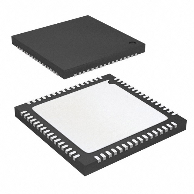
Analog Devices Inc. AD9863BCP-50
- Part No.:
- AD9863BCP-50
- Manufacturer:
- Analog Devices Inc.
- Category:
- RF Front End (LNA + PA)
- Package:
- 64-VFQFN Exposed Pad, CSP
- Datasheet:
-
 AD9863BCP-50.pdf
- Description:
- IC FRONT-END MIXED SGNL 64-LFCSP
- Quantity:
- Payment:

- Shipping:

Inventory:3,717
Please send an inquiry. Send us your inquiry, and we will respond immediately.
Product details
Overview
AD9863BCP-50 from Analog Devices is a mixed-signal front-end (MxFE™) baseband transceiver integrating dual 12-bit, 50 MSPS ADCs and dual 12-bit, 200 MSPS TxDACs with programmable interpolation (1×/2×/4×), internal PLL clock generation, and a flexible 24-bit I/O interface - optimized for broadband access and modem applications requiring high dynamic range and low power in compact form factors.
For engineers reviewing the AD9863BCP-50 datasheet, AD9863BCP-50 pinout, AD9863BCP-50 application, or AD9863BCP-50 equivalent, this page delivers verified specifications, package mapping, functional pin roles, real-world use cases, and validated alternative options - all grounded in Rev. B datasheet data and official Analog Devices documentation.
Technical Context
The AD9863BCP-50 implements independent Rx and Tx signal chains with dedicated analog supplies (AVDD, DRVDD, DVDD), configurable power-down control (RxPWRDWN/TxPWRDWN), and dual reference paths (REFT/REFB/VREF for ADC; REFIO/FSADJ for DAC). Its timing generation block supports single-reference clock operation via a programmable PLL with 32–350 MHz output range and selectable divide/multiply ratios.
Interface flexibility includes half-duplex 24-bit parallel, half-duplex 12-bit interleaved, or full-duplex 12-bit interleaved modes - enabled by mode pins (e.g., IFACE1–IFACE3) or SPI configuration (SPI_CS/SPI_CLK/SPI_DIO/SPI_SDO). ADC latency is 5 clock cycles; DAC latency ranges from 7 (1×) to 83 (4×) DAC clock cycles.
Key Specifications
| Parameter | Value and Actual Design Meaning |
|---|---|
| ADC Resolution & Rate | 12-bit, 50 MSPS max - supports high-fidelity digitization of baseband signals up to 30 MHz input bandwidth. |
| DAC Resolution & Update Rate | 12-bit, 200 MSPS max with 1×/2×/4× interpolation - enables Nyquist-rate synthesis of wideband modulated waveforms. |
| Rx Dynamic Performance | SNR = 67 dBc, SINAD = 65.5 dBc at 10 MHz input - sufficient for 11-bit ENOB in broadband LAN and DSL receiver stages. |
| Tx Dynamic Performance | SFDR = 77 dBc (wideband), THD = −79 dBc at 1 MHz - meets spectral purity requirements for multi-carrier OFDM transmission. |
| Power Consumption | Rx path: 103 mA @ 50 MSPS; Tx path: 70 mA @ 20 mA full-scale - enables thermal-constrained designs like PCMCIA cards. |
| Reference Architecture | Separate internal references: 1.0 V for ADC (REFT/REFB/VREF), 1.23 V bandgap for DAC (REFIO) - minimizes crosstalk and simplifies decoupling. |
| Operating Temperature | −40°C to +85°C ambient - qualified for industrial and outdoor broadband infrastructure deployments. |
Pinout & Package
AD9863BCP-50 is housed in a 64-lead LFCSP package (9 mm × 9 mm footprint, <0.9 mm height) with exposed paddle requiring solid ground connection per datasheet Figure 3 and Table 8.
| Pin/Terminal | Circuit Role | Design Meaning |
|---|---|---|
| CLKIN1 / CLKIN2 | Primary and secondary clock inputs | Supports independent Rx/Tx clocking or single-reference PLL operation; 1–200 MHz range with PLL bypass option. |
| VIN+A / VIN−A / VIN+B / VIN−B | Differential ADC analog inputs | 2 V p-p differential input range; 2 kΩ input resistance; 5 pF input capacitance - compatible with transformer-coupled or active baseband interfaces. |
| IOUT+A / IOUT−A / IOUT+B / IOUT−B | Differential DAC current outputs | 20 mA full-scale output into 100 Ω differential load; requires external termination (e.g., 50 Ω per leg) per Figure 2. |
| RxPWRDWN / TxPWRDWN | Analog power-down controls | Independent hardware pins enabling rapid shutdown of Rx or Tx analog sections - reduces quiescent current to 5 mA / 2 mA respectively. |
| SPI_CS / SPI_CLK / SPI_DIO / SPI_SDO | 4-wire serial programming interface | Enables full register-level configuration including gain, offset, interpolation rate, and data format - replaces mode-pin setup for complex systems. |
| U11–U0 / L11–L0 | Upper and lower 12-bit data bus | 24-bit bidirectional I/O supporting HD24, HD12, FD, or clone modes - reduces FPGA/DSP pin count and PCB routing complexity. |
Key Features
| Feature | Design Value |
|---|---|
| Dual-path independent power control | Hardware RxPWRDWN/TxPWRDWN pins allow selective analog section shutdown - critical for burst-mode communication protocols. |
| Programmable interpolation filters | 1×/2×/4× selectable DAC interpolation with defined latency (7/35/83 cycles) - enables trade-off between output bandwidth and digital processing load. |
| Flexible clock architecture | Integrated PLL with 16–200 MHz input and 32–350 MHz output - eliminates need for external clock synthesizers in cost-sensitive modems. |
| Low-power ADC operating modes | Three power states: normal (103 mA), low power (69 mA @ 50 MSPS), ultralow power (55 mA @ 20 MSPS) - extends battery life in portable CPE. |
| Configurable I/O interface | Mode-pin or SPI selection between HD24, HD12, FD, and clone protocols - ensures interoperability with legacy and next-gen DSP back ends. |
Applications
| Broadband DSL Modem | Cable Modem Termination System (CMTS) |
|---|---|
|
Use Scenario: Full-duplex upstream/downstream signal conditioning in residential DSLAM line cards. IC Role / Device Role / Timing Role: Baseband transceiver handling simultaneous 50 MSPS ADC sampling and 200 MSPS DAC reconstruction with shared clock domain. Use Value: Integrated dual-path architecture eliminates discrete ADC/DAC/PLL components - reducing BOM count by ≥7 parts and board area by >35%. |
Use Scenario: Multi-channel upstream channel aggregation in headend CMTS equipment. IC Role / Device Role / Timing Role: High-linearity 12-bit ADC digitizing multiple 5–65 MHz upstream QPSK/QAM signals with <1.2 ps rms jitter. Use Value: 80 dB crosstalk suppression between ADC channels prevents inter-channel interference in dense multi-port configurations. |
| Wireless Broadband Access Point | Industrial Ethernet Gateway |
|
Use Scenario: OFDM-based point-to-multipoint base station radio unit for 5 GHz unlicensed bands. IC Role / Device Role / Timing Role: Transmit path generating 20 MHz bandwidth OFDM waveforms with SFDR >72 dBc (narrowband) using 4× interpolation. Use Value: Measured IMD performance (Figures 27–45) confirms suitability for IEEE 802.16 WiMAX physical layer compliance testing. |
Use Scenario: Deterministic time-sensitive networking (TSN) gateway bridging fieldbus and Ethernet with precise timing alignment. IC Role / Device Role / Timing Role: Synchronized dual ADC/DAC pair providing sub-ns timestamped I/O for deterministic sensor actuation loops. Use Value: Aperture uncertainty of 1.2 ps rms and 5-cycle ADC latency enable µs-level closed-loop control in motion control systems. |
Equivalent & Alternatives
The following parts are listed as comparable options for similar mixed-signal front-end applications.
| Alternative Part | Technical Difference | Application Difference | Selection Advice |
|---|---|---|---|
| AD9862BCPZ | 10-bit ADCs (vs. 12-bit), no internal PLL, 48-lead LFCSP - lacks clock generation and resolution for high-SNR DSL receivers. | Targeted at cost-optimized cable modem downstream only; not suitable for full-duplex broadband access requiring matched Rx/Tx performance. | Select AD9862BCPZ only when system-level SNR budget allows ≤10-bit digitization and external clock synthesis is acceptable. |
| AD9865BCPZ | 12-bit ADCs at 80 MSPS, 250 MSPS DACs, integrated 1.8 V LDOs - higher speed but larger 72-lead LFCSP and increased power draw (145 mA Rx). | Designed for DOCSIS 3.1 CMTS upstream channel bonding; over-spec'd for DSL or fixed wireless where 50/200 MSPS suffices. | Choose AD9865BCPZ only when >65 MHz input bandwidth or >200 MSPS DAC update rate is required - otherwise AD9863BCP-50 offers better cost/power density. |
Compared with AD9862BCPZ and AD9865BCPZ, the AD9863BCP-50 uniquely balances 12-bit/50 MSPS ADC fidelity, 200 MSPS DAC throughput, on-chip PLL clocking, and 64-lead LFCSP compactness - making it the optimal choice for space-constrained, full-duplex broadband modems operating within 30 MHz analog bandwidth.
Availability
AD9863BCP-50 is available at Aetrix Electronics and suitable for broadband access, broadband LAN, and communications modem applications requiring stable component supply, long-term lifecycle support, and traceable sourcing for production programs.
Supply support for AD9863BCP-50 includes scheduled delivery planning, volume procurement assistance, BOM continuity management, traceable sourcing, and lifecycle availability coordination for OEM customers, industrial embedded developers, connected-device designers, and electronics production programs.
Manufacturer
Analog Devices, Inc. is a global leader in high-performance analog, mixed-signal, and digital signal processing semiconductors, headquartered in Norwood, MA, with R&D and manufacturing operations spanning 15+ countries.
The AD9863BCP-50 belongs to Analog Devices' MxFE™ (Mixed-Signal Front-End) family - engineered specifically for broadband communications infrastructure, emphasizing integration, dynamic range, and low-power operation in compact packages.
FAQ
What is the maximum ADC sample rate supported by the AD9863BCP-50?
The AD9863BCP-50 supports a maximum ADC sample rate of 50 MSPS, as confirmed in Table 2 of the Rev. B datasheet. This rate is optimized for baseband signals up to 30 MHz bandwidth and is maintained across the full −40°C to +85°C operating temperature range. The AD9863BCP-50 achieves 67 dBc SNR at this rate with a 10 MHz input tone, validating its suitability for DSL and broadband LAN receiver stages.
Does the AD9863BCP-50 include an integrated PLL, and what frequency ranges does it support?
Yes, the AD9863BCP-50 integrates a programmable phase-locked loop within its clock generation block. Per Table 5, the PLL accepts input frequencies from 16 MHz to 200 MHz and generates output frequencies from 32 MHz to 350 MHz - enabling single-reference clock operation for both ADC and DAC paths without external synthesizers. This capability is explicitly documented in the General Description and Clock Distribution Block sections of the datasheet.
What are the power-down current levels for the AD9863BCP-50's Rx and Tx analog sections?
According to Table 3, the AD9863BCP-50 draws 5 mA in Rx analog power-down mode and 2 mA in Tx analog power-down mode. These values are measured under standard conditions (AVDD = DVDD = 3.3 V) and represent guaranteed maximums. The independent RxPWRDWN and TxPWRDWN pins allow hardware-controlled entry into these low-current states - critical for energy-efficient burst-mode communication systems.
Can the AD9863BCP-50 operate in full-duplex mode, and how is the interface configured?
Yes, the AD9863BCP-50 supports full-duplex operation using interleaved 12-bit data transfers on its 24-bit I/O bus - with separate 12-bit ADC and TxDAC data lanes. Configuration is achieved via the IFACE3 pin (Table 8) or SPI register settings; full-duplex mode is explicitly listed in the Functional Block Diagram and General Description. This mode enables simultaneous transmit and receive in broadband modem applications without time-division multiplexing overhead.
What package type and thermal characteristics apply to the AD9863BCP-50?
The AD9863BCP-50 uses a 64-lead LFCSP package measuring 9 mm × 9 mm with an exposed paddle that must be soldered to the PCB ground plane. Thermal resistance is θJA = 24.2°C/W (paddle soldered) or 30.8°C/W (paddle unsoldered) on a 4-layer board - values specified in the Absolute Maximum Ratings section. This compact, thermally efficient package enables deployment in space-constrained applications such as PCMCIA cards and miniaturized CPE devices.
AD9863BCP-50 Specifications
- Product attributes
- Attribute value
- Manufacturer:
- Analog Devices Inc.
- Series:
- -
- Packaging:
- Bag
- Product Status:
- Obsolete
- RF Type:
- WLL, WLAN
- Frequency:
- -
- Features:
- 12-Bit ADC(s), 12-Bit DAC(s)
- Grade:
- -
- Qualification:
- -
- Supplier Device Package:
- 64-LFCSP-VQ (9x9)
AD9863BCP-50 FAQ
1.How can I place an order for AD9863BCP-50 through Aetrix?
Please submit a Request for Quotation (RFQ) for AD9863BCP-50 on Aetrix. Our sales agent will provide a competitive quotation and guide you through the order confirmation once you accept the terms.
2.Are the price and stock information for AD9863BCP-50 reliable?
The price and inventory of AD9863BCP-50 are updated periodically and may fluctuate due to market conditions. Stock and pricing data are typically refreshed every 24 hours. Quotation validity for AD9863BCP-50 is usually 5 days.
3.What payment methods are accepted for AD9863BCP-50?
We accept Wire Transfer, PayPal, Credit Card, Western Union, MoneyGram, and Escrow for AD9863BCP-50 transactions.
Note: Certain payment methods may incur a processing fee.
4.How is shipping managed for AD9863BCP-50?
AD9863BCP-50 orders can be shipped via leading logistics carriers, including DHL, UPS, FedEx, TNT, or Registered Mail.
Once your AD9863BCP-50 order is processed, you will receive an email with the shipment details and tracking number.
Note: Tracking information may take up to 24 hours to appear. Express delivery typically takes 3–5 business days.
5.How can I obtain technical support or documentation for AD9863BCP-50?
For technical support, including AD9863BCP-50 datasheets, pinout diagrams, or application guidance, please contact our engineering support team. They can provide detailed documentation and assistance for your AD9863BCP-50 requirements.
6.How does Aetrix verify that AD9863BCP-50 is sourced from the original manufacturer or authorized distributors?
All AD9863BCP-50 products on Aetrix are procured from qualified distributors and authorized channels. Our dedicated quality assurance team conducts strict verification, including traceability checks and, if necessary, third-party testing. This ensures that AD9863BCP-50 meets industry standards.
7.What is the process for return or replacement of AD9863BCP-50?
All AD9863BCP-50 units undergo pre-shipment inspection (PSI). If there is an issue with AD9863BCP-50, returns or replacements are accepted under the following conditions:
1.Quantity discrepancies, incorrect items, or visible external defects (such as breakage or corrosion), acknowledged by Aetrix.
2.The issue is reported within 90 days of delivery.
3.The AD9863BCP-50 part is unused and in its original packaging.
Return procedure for AD9863BCP-50:
1.Submit a request within 90 days.
2.Obtain a Return Material Authorization (RMA) from Aetrix.
AD9863BCP-50 Tags
-
RFX2401C
Skyworks Solutions Inc.
.jpg)
-
NRF21540-QDAA-R
Nordic Semiconductor ASA
-
NRF21540-QDAA-R7
Nordic Semiconductor ASA
-
RFX2411N
Skyworks Solutions Inc.
-
SE2438T-R
Skyworks Solutions Inc.
-
SKY66118-11
Skyworks Solutions Inc.
-
SKY85712-21
Skyworks Solutions Inc.

-
SKY85329-11
Skyworks Solutions Inc.
-
SKY66422-11
Skyworks Solutions Inc.

-
SKY66119-11
Skyworks Solutions Inc.
-
NJG1156PCD-TE1
Nisshinbo Micro Devices Inc.
-
SE2435L-R
Skyworks Solutions Inc.
Tech Hub

A practical engineering guide to 3.3V and 5V logic compatibility, input thresholds, resistor dividers, translator ICs, MOSFET level shifting, I2C pull-ups, timing limits and power-sequencing risks.

The 74HC595 uses push-pull logic outputs, while the TPIC6B595 uses 50 V open-drain DMOS sinks for higher-power loads. This guide compares timing, current limits, 3.3 V interfacing, load wiring, thermal…

The 74HC595 converts serial data into eight stable parallel outputs. This guide covers pin functions, shift and storage timing, OE and MR behavior, drive-current limits, cascading, voltage compatibilit…

A technical comparison of level-sensitive latches and edge-triggered flip-flops, covering timing windows, setup and hold limits, master–slave operation, time borrowing, race-through, HDL inference and…

A D latch stores one bit while Enable controls when data can pass. This reference covers gate-level operation, truth tables, transparency, setup and hold timing, LE versus OE, common ICs and practical …

An SR latch stores one bit through cross-coupled feedback. This engineering reference covers NOR and NAND implementations, truth tables, forbidden-state recovery, gated operation, switch debouncing, fa…

Latch circuits retain one bit through feedback. This technical reference covers SR and D latches, truth tables, transparency, timing limits, latch-versus-flip-flop behavior, applications and common log…

An engineering guide to LED driver operation, constant-current and constant-voltage outputs, linear and switching topologies, dimming, IC selection, calculations, replacement compatibility, and fault c…

Operational amplifier guide covering op amp basics, feedback, ideal vs real op amps, common configurations, buffer circuits, offset, bias current, gain-bandwidth, slew rate, rail-to-rail limits and sel…

Jumper cables guide covering safe connection order, red and black clamp placement, final ground connection, cable gauge, length, clamp quality, copper vs CCA cables, jump starter comparison and battery…


