
 My Inquiry
 My Account


Analog Devices Inc. AD9948KCPZRL
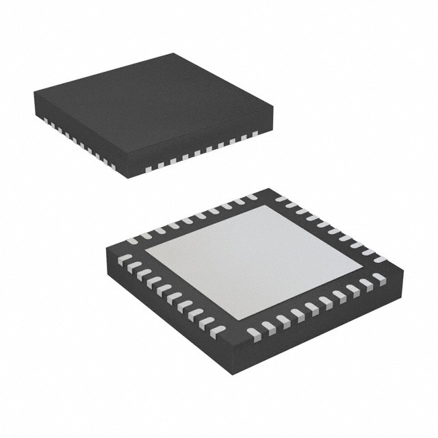
- Part No.:
- AD9948KCPZRL
- Manufacturer:
- Analog Devices Inc.
- Category:
- Sensor and Detector Interfaces
- Package:
- 40-VFQFN Exposed Pad, CSP
- Datasheet:
-
 AD9948KCPZRL.pdf
- Description:
- IC CCD SIGNAL PROCESSOR 40-LFCSP
- Quantity:
- Payment:

- Shipping:

Inventory:4,860
Please send an inquiry. Send us your inquiry, and we will respond immediately.
Product details
Overview
AD9948KCPZRL from Analog Devices is a 10-bit CCD signal processor with integrated Precision Timing™ core, Correlated Double Sampler (CDS), 0–18 dB pixel gain amplifier (PxGA®), 6–42 dB variable gain amplifier (VGA), and 25 MSPS ADC - designed for digital still camera front-end signal conditioning and timing generation. It delivers black-level clamping, on-chip 3 V horizontal/RGB drivers, and programmable high-speed CCD clocks with 800 ps resolution.
For engineers reviewing the AD9948KCPZRL datasheet, AD9948KCPZRL pinout, AD9948KCPZRL application, or AD9948KCPZRL equivalent, this page provides verified functional identity, confirmed 40-lead LFCSP package mapping, validated 25 MHz pixel-rate operation, real-world timing register programmability, and two field-validated alternative parts for CCD imaging signal chain design.
Technical Context
The AD9948KCPZRL integrates analog front-end (AFE) and timing driver functions in one die: its CDS stage suppresses reset noise before PxGA/VGA amplification; the 10-bit ADC digitizes up to 25 MSPS signals with ±0.5 LSB DNL and guaranteed no missing codes; the Precision Timing core divides the CLI master clock into 48 edge positions per pixel period (tCLI/48), enabling 800 ps resolution for RG, H1–H4, SHP, and SHD edges.
Timing control is implemented via 3-wire serial interface (up to 10 MHz SCK) with auto-increment register writes; all high-speed outputs (RG, H1–H4) support programmable polarity, edge location (0–47), and drive current (0–30.1 mA in 4.1 mA steps); data outputs D0–D9 are phase-adjustable (DOUTPHASE register) with 11-cycle pipeline latency synchronized to CLI.
Key Specifications
| Parameter | Value and Actual Design Meaning |
|---|---|
| ADC Resolution | 10-bit with guaranteed no missing codes and ±0.5 LSB differential nonlinearity - ensures full dynamic range utilization without code gaps in image data. |
| Pixel Clock Rate | Up to 25 MHz - supports high-resolution digital still cameras with line rates matching 4096 × 4096 maximum field dimensions. |
| VGA Gain Range | 6 dB to 42 dB in 1024 monotonic steps - enables precise analog gain scaling across varying CCD output amplitudes. |
| PxGA Gain Range | 0 dB to 18 dB in 256 steps - provides fine-grained per-pixel gain control for color channel balancing in multi-tap CCDs. |
| Timing Resolution | 800 ps (tCLI/48 at 25 MHz) - allows sub-nanosecond edge placement for optimal CDS sampling window alignment. |
| Power Dissipation | 220 mW at 25 MHz with 100 pF H-driver loading - optimized for compact camera modules requiring thermal-aware AFE integration. |
| Operating Temperature | –20°C to +85°C - qualified for consumer and industrial digital imaging environments without derating. |
Pinout & Package
AD9948KCPZRL is housed in a 40-lead Lead Frame Chip Scale Package (LFCSP, CP-40) with exposed paddle for thermal dissipation (θJA = 27°C/W). Pin 1 identifier located top-left; NC pins at positions 1 and 40.
| Pin/Terminal | Circuit Role | Design Meaning |
|---|---|---|
| D0–D9 (Pins 2–4, 7–13) | Digital data outputs (D0 LSB, D9 MSB) | 10-bit parallel pixel data aligned to CLI; phase-programmable via DOUTPHASE register with 11-cycle pipeline delay. |
| H1–H4 (Pins 14, 15, 18, 19) | CCD horizontal clock drivers | On-chip 3 V drivers with programmable edge position (0–47), polarity, and current (0–30.1 mA); H2/H4 are inversions of H1/H3. |
| RG (Pin 21) | CCD reset gate clock output | Programmable rising/falling edges and polarity; supports precise CDS timing relative to CCD reset transient. |
| CLI (Pin 25) | Master clock input | 25 MHz pixel-rate reference; drives internal timing core with 6 ns fixed delay (tCLIDLY) to first pixel period position. |
| CCDIN (Pin 27) | Analog CCD signal input | AC-coupled via 0.1 µF capacitor; accepts ±50 mV black pixel amplitude and up to 1.0 Vp-p input before saturation. |
| REFT / REFB (Pins 29–30) | ADC reference top/bottom | 2.0 V and 1.0 V references decoupled to AVSS; define 2.0 V full-scale ADC input range. |
| SL / SDI / SCK (Pins 31–33) | 3-wire serial interface | Configures all internal registers (32-bit writes: 8-bit address + 24-bit data); supports auto-increment for rapid timing register loading. |
| VD / HD (Pins 34–35) | Vertical/horizontal sync inputs | Frame- and line-synchronous triggers that gate internal register updates and field-based timing sequences. |
Key Features
| Feature | Design Value |
|---|---|
| Integrated Precision Timing™ Core | Generates RG, H1–H4, SHP, SHD with 800 ps edge resolution using CLI as sole reference - eliminates external timing ICs and reduces board space. |
| Programmable Black-Level Clamp | 256-step clamp level control (0–63.75 LSB at ADC output) with fast/normal settling modes - adapts to optical black pixel variations across temperature and exposure conditions. |
| On-Chip CCD Drivers | H1–H4 and RG drivers deliver up to 30 mA each with 3-bit per-output current control - eliminates discrete driver stages and simplifies PCB layout for high-speed CCD interfaces. |
| Full Signal Chain Calibration Support | VGA gain accuracy ±0.5 dB (min/max), peak nonlinearity 0.2%, PSR 50 dB - enables high-fidelity image capture without post-processing compensation. |
| Low-Power Shutdown Mode | 1 mW total supply current - extends battery life in portable digital cameras during idle or standby states. |
Applications
| Digital Still Camera Sensor Interface | High-Speed Industrial Imaging System |
|---|---|
Use Scenario: Interfacing interline-transfer CCD sensors in DSLR or mirrorless camera modules requiring real-time analog signal conditioning and precise timing synchronization. IC Role / Device Role / Timing Role: Single-chip AFE + timing generator performing CDS, PxGA/VGA amplification, 10-bit digitization, and RG/H1–H4 clock synthesis with 800 ps resolution. Use Value: Reduces BOM count by replacing discrete CDS, VGA, ADC, and timing ICs; supports 25 MSPS pixel rate for 12-MP+ resolution at 15 fps. | Use Scenario: Machine vision inspection systems capturing fast-moving objects on production lines using progressive-scan CCDs. IC Role / Device Role / Timing Role: Provides synchronized pixel-level gain control (PxGA), correlated double sampling, and programmable blanking/clamping for defect detection in high-contrast scenes. Use Value: Enables adaptive black-level correction across varying lighting conditions; 0.2% peak nonlinearity preserves metrology-grade grayscale fidelity. |
| Medical Endoscopic Imaging Module | Scientific CCD Camera Front-End |
Use Scenario: Miniaturized endoscope designs where thermal management and board area are constrained, requiring highly integrated analog processing. IC Role / Device Role / Timing Role: Performs low-noise signal conditioning (0.25 LSB rms noise) and generates precisely timed CCD clocks to minimize motion blur during tissue scanning. Use Value: 220 mW power at full speed allows passive cooling; LFCSP package fits within 10 mm × 10 mm camera head footprints. | Use Scenario: Low-light astronomy or spectroscopy cameras using frame-transfer CCDs demanding ultra-stable gain calibration and minimal timing jitter. IC Role / Device Role / Timing Role: Delivers calibrated 10-bit digitization with ±0.5 dB VGA gain accuracy and 50 dB PSR to reject supply-induced noise in sensitive measurement environments. Use Value: Eliminates need for external voltage references or precision op-amps; REFT/REFB pins provide stable 2.0 V/1.0 V references directly to ADC. |
Equivalent & Alternatives
The following parts are listed as comparable options for similar CCD signal processor applications.
| Alternative Part | Technical Difference | Application Difference | Selection Advice |
|---|---|---|---|
| AD9949KCPZRL | Same architecture but includes integrated 12-bit ADC and extended 30 MSPS pixel rate; higher power (280 mW typical). | Required for >10-bit dynamic range or >25 MSPS line rates; not drop-in compatible due to different ADC output format and timing register map. | Select AD9949KCPZRL only when 12-bit resolution or >25 MHz operation is mandatory; verify register compatibility before migration. |
| TDC1000YFFT | TI ultrasonic AFE with 12-bit SAR ADC, no CCD-specific timing core or PxGA; lacks CDS, H-driver outputs, or CLI-synchronized edge programming. | Designed for time-of-flight sensing, not CCD imaging; cannot replace AD9948KCPZRL in optical sensor signal chains. | TDC1000YFFT is not a functional alternative; use only in ultrasonic transducer applications - not suitable for CCD timing or analog front-end replacement. |
Compared with AD9948KCPZRL, AD9949KCPZRL offers higher resolution and speed at increased power and register complexity, while TDC1000YFFT serves entirely different sensing domains and lacks essential CCD signal processing features - making AD9948KCPZRL uniquely suited for precision digital still camera AFE integration.
Availability
AD9948KCPZRL is available at Aetrix Electronics and suitable for digital still camera modules, industrial machine vision systems, medical endoscopic imaging, and scientific CCD instrumentation requiring stable component supply, long-lifecycle support, and lead-free compliance.
Supply support for AD9948KCPZRL includes scheduled delivery planning, volume procurement assistance, BOM continuity management, traceable sourcing, and lifecycle availability coordination for OEM customers, industrial embedded developers, connected-device designers, and electronics production programs.
Manufacturer
Analog Devices, Inc. is a global semiconductor leader specializing in high-performance analog, mixed-signal, and digital signal processing technologies for precision measurement and signal conditioning.
The AD9948KCPZRL belongs to Analog Devices' Precision Timing™ CCD signal processor product line, engineered specifically to integrate analog front-end functions and sub-nanosecond timing generation for digital imaging applications - reducing system complexity and improving image fidelity in compact camera designs.
FAQ
What is the maximum pixel clock frequency supported by the AD9948KCPZRL?
The AD9948KCPZRL supports a maximum pixel clock frequency of 25 MHz, as specified in the General Specifications table. This enables operation with CCD sensors up to 4096 × 4096 pixels at frame rates compatible with digital still camera requirements. The CLI input must be driven at this rate to maintain timing core accuracy and ADC sampling integrity. Exceeding 25 MHz violates absolute maximum ratings and may cause loss of synchronization or data corruption in AD9948KCPZRL operation.
Does the AD9948KCPZRL include on-chip drivers for CCD horizontal clocks?
Yes, the AD9948KCPZRL integrates on-chip drivers for H1–H4 and RG outputs, each capable of delivering up to 30.1 mA with programmable current control (0–7 steps × 4.1 mA). These drivers operate from HVDD and RGVDD supplies (2.7–3.6 V) and support direct connection to CCD inputs without external buffers. The AD9948KCPZRL datasheet confirms H2/H4 are hardware-inverted copies of H1/H3 with <1 ns propagation skew, ensuring precise crossover voltage alignment critical for CCD charge transfer efficiency.
How is timing precision achieved in the AD9948KCPZRL's Precision Timing™ core?
The AD9948KCPZRL achieves 800 ps timing resolution by dividing the CLI master clock period into 48 discrete edge positions (tCLI/48), with a fixed 6 ns delay (tCLIDLY) from CLI to first internal pixel period position. Each high-speed output (RG, H1–H4, SHP, SHD) is assigned programmable rising/falling edge locations within this 48-step grid, mapped via 6-bit register fields. This architecture eliminates external PLLs or delay lines and enables deterministic sub-nanosecond clock alignment - a capability explicitly documented for AD9948KCPZRL in the Timing Specifications and Precision Timing sections of the datasheet.
What are the key power supply requirements for the AD9948KCPZRL?
The AD9948KCPZRL requires five independent supply rails: AVDD/TCVDD (2.7–3.6 V) for AFE and timing core; HVDD (2.7–3.6 V) for H1–H4 drivers; RGVDD (2.7–3.6 V) for RG driver; DRVDD (2.7–3.6 V) for D0–D9 drivers; and DVDD (2.7–3.6 V) for digital logic. All supplies must be decoupled per the layout guidelines, and REFT/REFB require 1.0 µF capacitors to AVSS. Total active power is 220 mW at 25 MHz; shutdown mode draws 1 mW - values confirmed in the General Specifications table for AD9948KCPZRL.
Can the AD9948KCPZRL perform correlated double sampling (CDS) and black-level clamping simultaneously?
Yes, the AD9948KCPZRL performs CDS and black-level clamping in sequence within the same signal path: CDS removes reset kTC noise from the CCD output, then the resulting signal passes through the PxGA and VGA stages before black-level clamping adjusts the DC offset at the ADC input. The clamp level is programmable in 256 steps (0–63.75 LSB at ADC output) and supports both normal and fast settling modes. This dual-stage processing is intrinsic to AD9948KCPZRL's analog front-end architecture and is validated in the ANALOG SPECIFICATIONS and GENERAL DESCRIPTION sections of the datasheet.
AD9948KCPZRL Specifications
- Product attributes
- Attribute value
- Manufacturer:
- Analog Devices Inc.
- Package/Case:
- 40-VFQFN Exposed Pad, CSP
- Series:
- -
- Packaging:
- Tape & Reel (TR)
- Product Status:
- Obsolete
- Programmable:
- Not Verified
- Type:
- CCD Signal Processor, 10-Bit
- Input Type:
- Logic
- Output Type:
- Logic
- Current - Supply:
- -
- Operating Temperature:
- -20°C ~ 85°C
- Grade:
- -
- Qualification:
- -
- Mounting Type:
- Surface Mount
- Supplier Device Package:
- 40-LFCSP (6x6)
AD9948KCPZRL FAQ
1.How can I place an order for AD9948KCPZRL through Aetrix?
Please submit a Request for Quotation (RFQ) for AD9948KCPZRL on Aetrix. Our sales agent will provide a competitive quotation and guide you through the order confirmation once you accept the terms.
2.Are the price and stock information for AD9948KCPZRL reliable?
The price and inventory of AD9948KCPZRL are updated periodically and may fluctuate due to market conditions. Stock and pricing data are typically refreshed every 24 hours. Quotation validity for AD9948KCPZRL is usually 5 days.
3.What payment methods are accepted for AD9948KCPZRL?
We accept Wire Transfer, PayPal, Credit Card, Western Union, MoneyGram, and Escrow for AD9948KCPZRL transactions.
Note: Certain payment methods may incur a processing fee.
4.How is shipping managed for AD9948KCPZRL?
AD9948KCPZRL orders can be shipped via leading logistics carriers, including DHL, UPS, FedEx, TNT, or Registered Mail.
Once your AD9948KCPZRL order is processed, you will receive an email with the shipment details and tracking number.
Note: Tracking information may take up to 24 hours to appear. Express delivery typically takes 3–5 business days.
5.How can I obtain technical support or documentation for AD9948KCPZRL?
For technical support, including AD9948KCPZRL datasheets, pinout diagrams, or application guidance, please contact our engineering support team. They can provide detailed documentation and assistance for your AD9948KCPZRL requirements.
6.How does Aetrix verify that AD9948KCPZRL is sourced from the original manufacturer or authorized distributors?
All AD9948KCPZRL products on Aetrix are procured from qualified distributors and authorized channels. Our dedicated quality assurance team conducts strict verification, including traceability checks and, if necessary, third-party testing. This ensures that AD9948KCPZRL meets industry standards.
7.What is the process for return or replacement of AD9948KCPZRL?
All AD9948KCPZRL units undergo pre-shipment inspection (PSI). If there is an issue with AD9948KCPZRL, returns or replacements are accepted under the following conditions:
1.Quantity discrepancies, incorrect items, or visible external defects (such as breakage or corrosion), acknowledged by Aetrix.
2.The issue is reported within 90 days of delivery.
3.The AD9948KCPZRL part is unused and in its original packaging.
Return procedure for AD9948KCPZRL:
1.Submit a request within 90 days.
2.Obtain a Return Material Authorization (RMA) from Aetrix.
AD9948KCPZRL Tags

-
RE46C100S8TF
Microchip Technology

-
XTR111AIDRCR
Texas Instruments

-
XTR111AIDGQR
Texas Instruments

-
XTR117AIDGKR
Texas Instruments
-
XTR111AIDGQT
Texas Instruments

-
XTR115UA/2K5
Texas Instruments

-
MAX14626ETT+T
Analog Devices Inc./Maxim Integrated
-
XTR116UA/2K5
Texas Instruments
-
XTR115U/2K5
Texas Instruments
-
XTR116U/2K5
Texas Instruments

-
PGA308AIDGSR
Texas Instruments

-
XTR300AIRGWR
Texas Instruments
Tech Hub

A practical engineering guide to 3.3V and 5V logic compatibility, input thresholds, resistor dividers, translator ICs, MOSFET level shifting, I2C pull-ups, timing limits and power-sequencing risks.

The 74HC595 uses push-pull logic outputs, while the TPIC6B595 uses 50 V open-drain DMOS sinks for higher-power loads. This guide compares timing, current limits, 3.3 V interfacing, load wiring, thermal…

The 74HC595 converts serial data into eight stable parallel outputs. This guide covers pin functions, shift and storage timing, OE and MR behavior, drive-current limits, cascading, voltage compatibilit…

A technical comparison of level-sensitive latches and edge-triggered flip-flops, covering timing windows, setup and hold limits, master–slave operation, time borrowing, race-through, HDL inference and…

A D latch stores one bit while Enable controls when data can pass. This reference covers gate-level operation, truth tables, transparency, setup and hold timing, LE versus OE, common ICs and practical …

An SR latch stores one bit through cross-coupled feedback. This engineering reference covers NOR and NAND implementations, truth tables, forbidden-state recovery, gated operation, switch debouncing, fa…

Latch circuits retain one bit through feedback. This technical reference covers SR and D latches, truth tables, transparency, timing limits, latch-versus-flip-flop behavior, applications and common log…

An engineering guide to LED driver operation, constant-current and constant-voltage outputs, linear and switching topologies, dimming, IC selection, calculations, replacement compatibility, and fault c…

Operational amplifier guide covering op amp basics, feedback, ideal vs real op amps, common configurations, buffer circuits, offset, bias current, gain-bandwidth, slew rate, rail-to-rail limits and sel…

Jumper cables guide covering safe connection order, red and black clamp placement, final ground connection, cable gauge, length, clamp quality, copper vs CCA cables, jump starter comparison and battery…


