
 My Inquiry
 My Account


Analog Devices Inc. AD9991KCPZRL
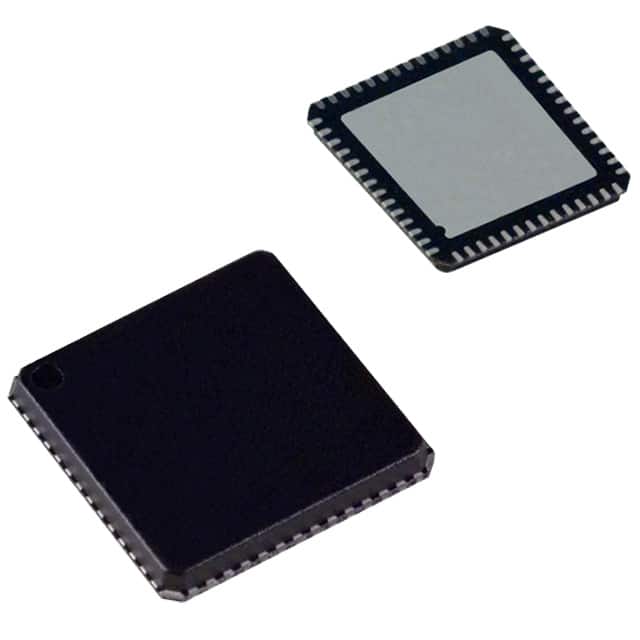
- Part No.:
- AD9991KCPZRL
- Manufacturer:
- Analog Devices Inc.
- Category:
- Sensor and Detector Interfaces
- Package:
- 56-VFQFN Exposed Pad, CSP
- Datasheet:
-
 AD9991KCPZRL.pdf
- Description:
- IC CCD SIGNAL PROCESSOR 56-LFCSP
- Quantity:
- Payment:

- Shipping:

Inventory:1,705
Please send an inquiry. Send us your inquiry, and we will respond immediately.
Product details
Overview
AD9991KCPZRL from Analog Devices is a 10-bit CCD signal processor with integrated Precision Timing™ generator, designed for digital still cameras and camcorders. It combines correlated double sampling (CDS), 6–42 dB VGA, black level clamp, and 10-bit 27 MHz ADC in a single 56-lead LFCSP package. Its on-chip timing core delivers 800 ps resolution at 27 MHz for precise vertical/horizontal clock generation.
For engineers reviewing the AD9991KCPZRL datasheet, AD9991KCPZRL pinout, AD9991KCPZRL application, or AD9991KCPZRL equivalent, key selection considerations include its 6-phase vertical clock support, programmable H/V timing registers, 56-lead LFCSP thermal performance (θJA = 25°C/W), and full 3-wire serial interface control of CCD sensor timing and analog front-end parameters.
Technical Context
The AD9991KCPZRL implements a dual-domain architecture: an analog front end (AFE) with CDS, VGA, clamp, and 10-bit ADC operating up to 27 MHz pixel rate; and a fully programmable Precision Timing core generating RG, H1–H4, V1–V6, VSG1–VSG5, SUBCK, and MSHUT/STROBE signals. All high-speed clocks are resolved to 48 edge positions per pixel period, enabling sub-nanosecond alignment.
Timing is configured via 3-wire serial interface (SL/SCK/SDI) with register banks supporting independent V-sequence programming (up to 10 sequences), H-blanking pattern control, shutter mode selection (electronic/mechanical), and drive strength adjustment (0–30 mA per H/RG output). The device operates across –20°C to +85°C with five independent supply domains (AVDD, TCVDD, RGVDD, HVDD, DRVDD, DVDD).
Key Specifications
| Parameter | Value and Actual Design Meaning |
|---|---|
| ADC Resolution | 10-bit - delivers 1024 discrete output levels for digitizing CCD analog video signals. |
| Pixel Clock Rate | Up to 27 MHz - supports high-resolution, high-frame-rate imaging in digital still and video cameras. |
| VGA Gain Range | 6 dB to 42 dB in 1024 steps - enables fine-grained exposure control across varying light conditions. |
| Timing Resolution | 800 ps at 27 MHz - allows sub-pixel-edge precision for optimizing CDS sampling and CCD clock phasing. |
| Vertical Clock Support | 6-phase V1–V6 + 5-sensor-gate VSG1–VSG5 - matches complex interline-transfer CCD architectures. |
| Package | 56-lead LFCSP (CP-56) - compact 8 mm × 8 mm exposed-pad package with θJA = 25°C/W for thermal management. |
| Operating Temperature | –20°C to +85°C - qualified for industrial and consumer imaging environments without derating. |
Pinout & Package
AD9991KCPZRL is housed in a 56-lead Lead Frame Chip Scale Package (LFCSP, CP-56) with exposed thermal pad. Pin layout supports dedicated analog/digital/power domains: AVDD/AVSS for AFE, TCVDD/TCVSS for timing core, HVDD/HVSS for H-drivers, RGVDD/RGVSS for RG driver, DRVDD/DRVSS for data outputs, and DVDD/DVSS for digital logic and serial interface.
| Pin/Terminal | Circuit Role | Design Meaning |
|---|---|---|
| CLI | Reference Clock Input | Accepts master pixel clock (up to 27 MHz); feeds Precision Timing core and synchronizes all internal counters. |
| CCDIN | Analog Signal Input | High-impedance input for CCD analog video signal; connects directly to CDS stage with ±50 mV black-level range. |
| H1–H4, RG | CCD Horizontal & Reset Gate Outputs | On-chip drivers deliver programmable 0–30 mA current; support direct connection to CCD H/RG inputs without external buffers. |
| V1–V6, VSG1–VSG5, SUBCK | Vertical Timing Outputs | Digital outputs for CCD vertical transfer, sensor gate, and substrate clock; require external V-driver for voltage translation. |
| D0–D9, DCLK | Digital Data Interface | 10-bit parallel LVCMOS outputs with programmable phase (0–47 pixel positions) and 0–12 ns output delay for timing alignment. |
| SL, SCK, SDI | 3-Wire Serial Interface | Asynchronous control bus (max 10 MHz SCK) for configuring timing registers, gain, clamp level, and operational modes. |
Key Features
| Feature | Design Value |
|---|---|
| 6-Phase Vertical Transfer Clock Generation | Enables full support for advanced interline-transfer CCDs requiring precise V1–V6 sequencing and line-alternation patterns. |
| Correlated Double Sampling (CDS) | Reduces reset noise and fixed-pattern noise by sampling CCD signal before and after integration, with 500 mV transient tolerance. |
| Programmable Horizontal Blanking (HBLK) | Allows dynamic blanking window definition per field region via toggle-position registers, critical for optical black calibration. |
| Electronic/Mechanical Shutter Control | MSHUT and STROBE outputs provide synchronized pulses for mechanical shutter actuation and flash triggering with sub-microsecond timing. |
| On-Chip Crystal Driver (CLO) | CLO pin outputs inverted CLI signal, enabling direct crystal oscillation between CLI/CLO pins-eliminates external oscillator component. |
Applications
| Digital Still Cameras | Digital Video Camcorders |
|---|---|
Use Scenario: High-resolution image capture with auto-exposure and low-noise readout in DSLR and mirrorless systems. IC Role / Device Role / Timing Role: Primary CCD signal processor handling analog signal conditioning, digitization, and full CCD timing generation including VSG, SUBCK, and shutter synchronization. Use Value: Integrated 10-bit ADC and 42 dB VGA enable >60 dB dynamic range; 800 ps timing resolution optimizes CDS sampling to suppress kTC noise. |
Use Scenario: Progressive-scan video recording with real-time black-level correction and frame-rate flexibility. IC Role / Device Role / Timing Role: Central timing and AFE controller managing H/V clock sequencing, horizontal blanking, and optical black clamping across variable frame rates. Use Value: Programmable V-sequences (up to 10) allow distinct CLPOB/PBLK patterns per field region-essential for accurate dark-frame subtraction in video pipelines. |
| Industrial Imaging Systems | Machine Vision Inspection |
Use Scenario: High-speed line-scan or area-scan inspection in factory automation with precise exposure control. IC Role / Device Role / Timing Role: Timing-critical CCD interface IC providing deterministic pipeline latency (11 cycles), sub-pixel clock alignment, and trigger-synchronized readout. Use Value: Fixed 11-cycle pipeline delay and programmable DCLK phase ensure deterministic timing for FPGA-based image acquisition engines. |
Use Scenario: Defect detection using multi-region ROI readout and calibrated dark-signal subtraction. IC Role / Device Role / Timing Role: Dual-role device performing both analog signal conditioning (CDS, clamp, VGA) and programmable timing for sensor gating and strobe synchronization. Use Value: Independent HBLK and CLPOB pattern control per V-sequence enables per-line black-level calibration-critical for uniformity in high-precision metrology. |
Equivalent & Alternatives
The following parts are listed as comparable options for similar CCD signal processor applications.
| Alternative Part | Technical Difference | Application Difference | Selection Advice |
|---|---|---|---|
| TDC1304IPWPR | 12-bit SAR ADC, no integrated timing generator; requires external FPGA or ASIC for CCD clock synthesis. | Limited to simpler CCD architectures lacking 6-phase vertical or sensor-gate control; better suited for scientific CCDs with custom timing. | Select when higher ADC resolution (12-bit) is prioritized over integration; expect added board complexity and firmware overhead. |
| LM98714BCMTX/NOPB | 14-bit ADC, integrated timing but only 4-phase vertical support; lacks SUBCK, VSG, and electronic shutter modes. | Targeted at legacy linear CCDs and fax/scanner applications-not optimized for modern interline-transfer video sensors. | Choose for cost-sensitive, lower-performance scanning systems where 6-phase timing and shutter control are unnecessary. |
Compared with AD9991KCPZRL, TDC1304IPWPR offers higher resolution but no timing engine, increasing system design effort; LM98714BCMTX/NOPB provides greater bit depth but omits critical features for video CCDs-making AD9991KCPZRL the only option supporting full 6-phase vertical timing, SUBCK, and MSHUT/STROBE in a single chip.
Availability
AD9991KCPZRL is available at Aetrix Electronics and suitable for digital still cameras, industrial imaging systems, and machine vision inspection requiring stable component supply, long-term lifecycle support, and traceable sourcing for production programs.
Supply support for AD9991KCPZRL includes scheduled delivery planning, volume procurement assistance, BOM continuity management, traceable sourcing, and lifecycle availability coordination for OEM customers, industrial embedded developers, connected-device designers, and electronics production programs.
Manufacturer
Analog Devices, Inc. is a global leader in high-performance analog, mixed-signal, and digital signal processing semiconductors, headquartered in Norwood, MA.
The AD9991KCPZRL belongs to Analog Devices' Precision Timing™ CCD signal processor family, engineered specifically for high-fidelity, low-noise imaging in digital photography and video capture systems requiring tight synchronization between analog signal chain and sensor timing.
FAQ
What is the maximum pixel clock frequency supported by the AD9991KCPZRL?
The AD9991KCPZRL supports a maximum CLI (clock input) frequency of 27 MHz, which defines the upper limit for pixel rate operation. At this rate, the Precision Timing core maintains 800 ps resolution per edge position, and the 10-bit ADC achieves full specification performance including DNL ≤ ±0.5 LSB and total output noise of 0.25 LSB rms. Operation above 27 MHz is not characterized or guaranteed.
Does the AD9991KCPZRL include on-chip drivers for all CCD clock signals?
The AD9991KCPZRL integrates on-chip drivers for RG and H1–H4 outputs, each programmable from 0 to 30 mA in 4.1 mA steps. However, it does not include drivers for vertical clocks (V1–V6), sensor gate pulses (VSG1–VSG5), or SUBCK-these require external V-driver circuitry. The AD9991KCPZRL provides the timing logic and digital outputs only for those signals.
How many independent vertical timing sequences can be programmed in the AD9991KCPZRL?
The AD9991KCPZRL supports up to 10 independent vertical timing sequences (V-sequences), each configurable with unique V1–V6, VSG1–VSG5, and SUBCK patterns. These sequences can be assigned to different regions of a field using sequence change positions, enabling per-region control of CLPOB, PBLK, and HBLK-critical for advanced optical black calibration in video applications.
What is the function of the CLO pin on the AD9991KCPZRL?
The CLO (Clock Output) pin on the AD9991KCPZRL outputs the inverse of the CLI input signal and is intended to drive an external crystal connected between CLI and CLO. This configuration forms a self-contained crystal oscillator, eliminating the need for an external clock source or oscillator IC. The AD9991KCPZRL uses this internally generated clock for all timing operations.
What power supply domains does the AD9991KCPZRL require, and why are they separated?
The AD9991KCPZRL requires six independent supply domains: AVDD/AVSS (AFE analog), TCVDD/TCVSS (timing core analog), RGVDD/RGVSS (RG driver), HVDD/HVSS (H-driver), DRVDD/DRVSS (data output driver), and DVDD/DVSS (digital logic). This separation minimizes noise coupling between sensitive analog signal paths (CDS, ADC) and high-current digital switching (H/RG outputs), preserving SNR and timing integrity.
AD9991KCPZRL Specifications
- Product attributes
- Attribute value
- Manufacturer:
- Analog Devices Inc.
- Package/Case:
- 56-VFQFN Exposed Pad, CSP
- Series:
- -
- Packaging:
- Tape & Reel (TR)
- Product Status:
- Obsolete
- Programmable:
- Not Verified
- Type:
- CCD Signal Processor, 10-Bit
- Input Type:
- Logic
- Output Type:
- Logic
- Current - Supply:
- -
- Operating Temperature:
- -20°C ~ 85°C
- Grade:
- -
- Qualification:
- -
- Mounting Type:
- Surface Mount
- Supplier Device Package:
- 56-LFCSP-VQ (8x8)
AD9991KCPZRL FAQ
1.How can I place an order for AD9991KCPZRL through Aetrix?
Please submit a Request for Quotation (RFQ) for AD9991KCPZRL on Aetrix. Our sales agent will provide a competitive quotation and guide you through the order confirmation once you accept the terms.
2.Are the price and stock information for AD9991KCPZRL reliable?
The price and inventory of AD9991KCPZRL are updated periodically and may fluctuate due to market conditions. Stock and pricing data are typically refreshed every 24 hours. Quotation validity for AD9991KCPZRL is usually 5 days.
3.What payment methods are accepted for AD9991KCPZRL?
We accept Wire Transfer, PayPal, Credit Card, Western Union, MoneyGram, and Escrow for AD9991KCPZRL transactions.
Note: Certain payment methods may incur a processing fee.
4.How is shipping managed for AD9991KCPZRL?
AD9991KCPZRL orders can be shipped via leading logistics carriers, including DHL, UPS, FedEx, TNT, or Registered Mail.
Once your AD9991KCPZRL order is processed, you will receive an email with the shipment details and tracking number.
Note: Tracking information may take up to 24 hours to appear. Express delivery typically takes 3–5 business days.
5.How can I obtain technical support or documentation for AD9991KCPZRL?
For technical support, including AD9991KCPZRL datasheets, pinout diagrams, or application guidance, please contact our engineering support team. They can provide detailed documentation and assistance for your AD9991KCPZRL requirements.
6.How does Aetrix verify that AD9991KCPZRL is sourced from the original manufacturer or authorized distributors?
All AD9991KCPZRL products on Aetrix are procured from qualified distributors and authorized channels. Our dedicated quality assurance team conducts strict verification, including traceability checks and, if necessary, third-party testing. This ensures that AD9991KCPZRL meets industry standards.
7.What is the process for return or replacement of AD9991KCPZRL?
All AD9991KCPZRL units undergo pre-shipment inspection (PSI). If there is an issue with AD9991KCPZRL, returns or replacements are accepted under the following conditions:
1.Quantity discrepancies, incorrect items, or visible external defects (such as breakage or corrosion), acknowledged by Aetrix.
2.The issue is reported within 90 days of delivery.
3.The AD9991KCPZRL part is unused and in its original packaging.
Return procedure for AD9991KCPZRL:
1.Submit a request within 90 days.
2.Obtain a Return Material Authorization (RMA) from Aetrix.
AD9991KCPZRL Tags

-
RE46C100S8TF
Microchip Technology

-
XTR111AIDRCR
Texas Instruments

-
XTR111AIDGQR
Texas Instruments

-
XTR117AIDGKR
Texas Instruments
-
XTR111AIDGQT
Texas Instruments

-
XTR115UA/2K5
Texas Instruments

-
MAX14626ETT+T
Analog Devices Inc./Maxim Integrated
-
XTR116UA/2K5
Texas Instruments
-
XTR115U/2K5
Texas Instruments
-
XTR116U/2K5
Texas Instruments

-
PGA308AIDGSR
Texas Instruments

-
XTR300AIRGWR
Texas Instruments
Tech Hub

A practical engineering guide to 3.3V and 5V logic compatibility, input thresholds, resistor dividers, translator ICs, MOSFET level shifting, I2C pull-ups, timing limits and power-sequencing risks.

The 74HC595 uses push-pull logic outputs, while the TPIC6B595 uses 50 V open-drain DMOS sinks for higher-power loads. This guide compares timing, current limits, 3.3 V interfacing, load wiring, thermal…

The 74HC595 converts serial data into eight stable parallel outputs. This guide covers pin functions, shift and storage timing, OE and MR behavior, drive-current limits, cascading, voltage compatibilit…

A technical comparison of level-sensitive latches and edge-triggered flip-flops, covering timing windows, setup and hold limits, master–slave operation, time borrowing, race-through, HDL inference and…

A D latch stores one bit while Enable controls when data can pass. This reference covers gate-level operation, truth tables, transparency, setup and hold timing, LE versus OE, common ICs and practical …

An SR latch stores one bit through cross-coupled feedback. This engineering reference covers NOR and NAND implementations, truth tables, forbidden-state recovery, gated operation, switch debouncing, fa…

Latch circuits retain one bit through feedback. This technical reference covers SR and D latches, truth tables, transparency, timing limits, latch-versus-flip-flop behavior, applications and common log…

An engineering guide to LED driver operation, constant-current and constant-voltage outputs, linear and switching topologies, dimming, IC selection, calculations, replacement compatibility, and fault c…

Operational amplifier guide covering op amp basics, feedback, ideal vs real op amps, common configurations, buffer circuits, offset, bias current, gain-bandwidth, slew rate, rail-to-rail limits and sel…

Jumper cables guide covering safe connection order, red and black clamp placement, final ground connection, cable gauge, length, clamp quality, copper vs CCA cables, jump starter comparison and battery…


