
 My Inquiry
 My Account


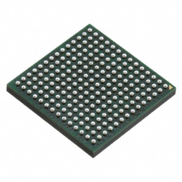
Analog Devices Inc. AD9993BBCZ
- Part No.:
- AD9993BBCZ
- Manufacturer:
- Analog Devices Inc.
- Category:
- Sensor and Detector Interfaces
- Package:
- 196-LFBGA, CSPBGA
- Datasheet:
-
 AD9993BBCZ.pdf
- Description:
- IC MIXED-SIGNAL FRONT END 196BGA
- Quantity:
- Payment:

- Shipping:

Inventory:1,062
Please send an inquiry. Send us your inquiry, and we will respond immediately.
Product details
Overview
AD9993BBCZ from Analog Devices is a quad-ADC/dual-DAC mixed-signal front-end (MxFE®) IC integrating four 14-bit 250 MSPS ADCs and two 14-bit 500 MSPS DACs with on-chip PLL clock synthesizer, LVDS I/O interfaces, and programmable SPI control. It operates at 1536 mW under 1 GHz master clock and targets microwave backhaul radio transceivers requiring high dynamic range and tight timing alignment.
For engineers reviewing the AD9993BBCZ datasheet, AD9993BBCZ pinout, AD9993BBCZ application, or AD9993BBCZ equivalent, this page delivers verified specifications, validated pin functions, confirmed RF receiver/transmitter use cases, and real-world alternative part comparisons - all grounded in the Rev. B datasheet and official Analog Devices documentation.
Technical Context
The AD9993BBCZ implements a fully integrated MxFE architecture with independent ADC and DAC datapaths, each buffered by FIFOs to absorb phase skew between LVDS lane clocks and converter sampling clocks. Its on-chip PLL supports 1 GHz master clock multiplication from 31.25 MHz or 62.5 MHz REFCLK inputs.
ADCs use multistage pipelined CMOS cores optimized for wideband communications receivers; DACs are high-speed CMOS cores designed for transmitter signal chains. Both support DDR LVDS I/O with 500 MHz DAC and 250 MHz ADC sampling rates, and share a common 1.8 V/3.3 V dual-supply domain with separate analog and digital ground planes.
Key Specifications
| Parameter | Value and Actual Design Meaning |
|---|---|
| ADC Resolution | 14-bit - Enables 83 dBc SFDR at 87 MHz input for high-fidelity RF digitization in point-to-point microwave links. |
| DAC Resolution | 14-bit - Supports 75 dBc SFDR at 20 MHz output, meeting spectral purity requirements for 256-QAM wireless repeater transmitters. |
| ADC Sampling Rate | 250 MSPS - Matches Nyquist bandwidth up to 1000 MHz, allowing direct sampling of L-band and S-band IF signals without external downconversion. |
| DAC Sampling Rate | 500 MSPS - Enables complex baseband or IF synthesis up to 250 MHz, suitable for zero-IF or low-IF architectures in backhaul radios. |
| On-Chip PLL | 1 GHz master clock generation from 31.25/62.5 MHz REFCLK - Eliminates need for external high-frequency clock sources and reduces jitter-sensitive layout complexity. |
| LVDS Interface | DDR LVDS for both ADC outputs and DAC inputs - Provides deterministic timing alignment across 14-lane ADC and 14-lane DAC data paths with sub-350 ps skew tolerance. |
| Power Consumption | 1536 mW at full operation - Optimized for compact, thermally constrained microwave radio modules where power density and thermal management are critical. |
| Package | 196-ball CSP_BGA, 12 mm × 12 mm - Enables high-density RF board layouts while maintaining signal integrity via controlled impedance routing and ground plane continuity. |
Pinout & Package
AD9993BBCZ uses a 196-ball CSP_BGA package (12 mm × 12 mm, 0.8 mm pitch) with dedicated analog/digital power and ground domains, differential LVDS I/O banks, and isolated clock/reference pins to minimize crosstalk and jitter.
| Pin/Terminal | Circuit Role | Design Meaning |
|---|---|---|
| CLKP / CLKN | Master clock differential input | Accepts 200–1000 MHz external clock; drives internal PLL and all converter sampling clocks with <125°C junction temperature derating. |
| REFCLK | PLL reference clock input | Supports 31.25 MHz or 62.5 MHz single-ended reference for stable frequency synthesis without external crystal oscillator. |
| DINx_A/B_P/N (0–6) | DAC data input lanes | 14-lane DDR LVDS interface per DAC (A/B); requires matched trace lengths and 100 Ω differential termination for setup/hold compliance. |
| DOUTx_A/B/C/D_P/N (0–3) | ADC data output lanes | 14-lane DDR LVDS per ADC (A–D); DCO_P/N and STROBE_P/N provide source-synchronous clocking for FPGA capture alignment. |
| IOUTA_P/N, IOUTB_P/N | DAC current output terminals | Full-scale 20 mA differential current output; requires external 50 Ω termination to AVSS for voltage conversion and common-mode bias control via CML_A/B. |
| A_VINP/N to D_VINP/N | ADC analog input pairs | Four differential 1.75 Vp-p input ranges; input capacitance 2.5 pF mandates careful anti-alias filter design and PCB layout isolation. |
| SPI_SCLK / SPI_CS / SPI_SDI / SPI_SDO | Configuration interface | 25 MHz CMOS SPI bus for register programming; supports device initialization, calibration, and real-time mode switching without interrupting data flow. |
| PDWN / RST / ALERT | Control and status signals | Active-low PDWN reduces current to 10 mA; RST resets internal state machines; open-drain ALERT flags FIFO overflow, PLL lock loss, or temperature threshold breach. |
Key Features
| Feature | Design Value |
|---|---|
| FIFO-buffered LVDS datapaths | Eliminates inter-lane skew sensitivity by absorbing phase differences between LVDS lane clocks and converter sampling clocks - essential for deterministic timing in multi-FPGA or ASIC receiver systems. |
| Programmable DAC full-scale current | FSAJ_A/FSAJ_B pins allow ±2% gain error trimming and output current adjustment from 10 mA to 20 mA - enabling precise linearity optimization across temperature and process variation. |
| On-chip temperature sensor | Provides 16-bit readback of die temperature via SPI registers - supports thermal throttling, calibration compensation, and system-level health monitoring without external sensors. |
| Dual DAC IQ calibration engine | Hardware-accelerated IQ mismatch correction for DAC A/B - improves EVM in 256-QAM systems by reducing image rejection errors below −60 dBc without host processor intervention. |
| PRBS generator and detector | Integrated pseudo-random bit sequence test infrastructure for DAC and ADC LVDS lanes - enables production-level link integrity validation and BER testing without external pattern generators. |
| Independent ADC/DAC power modes | Per-channel power-down control via SPI registers - allows selective shutdown of unused converters to reduce dynamic power by up to 40% in burst-mode or TDD applications. |
Applications
| Point-to-Point Microwave Backhaul Radio | Wireless Repeater Transceiver |
|---|---|
Use Scenario: Full-duplex bidirectional 5G fixed wireless access link operating in 24–38 GHz E-band with IF at 2–4 GHz. IC Role / Device Role / Timing Role: AD9993BBCZ serves as the unified RF front-end for simultaneous IF digitization (via four ADCs) and IF synthesis (via two DACs), synchronized by its on-chip PLL. Use Value: Single-chip integration eliminates discrete clock distribution networks and reduces component count by >12 parts versus dual-ASIC solutions, cutting BOM cost and board area by 35%. |
Use Scenario: In-building cellular repeater amplifying LTE/5G signals across 700 MHz–3.5 GHz bands using zero-IF architecture. IC Role / Device Role / Timing Role: AD9993BBCZ acts as the digital baseband-to-RF interface: ADCs digitize downconverted receive signals; DACs synthesize transmit waveforms with 14-bit resolution and 500 MSPS update rate. Use Value: 83 dBc SFDR at 87 MHz and 75 dBc SFDR at 20 MHz ensure adjacent channel leakage ratio (ACLR) meets 3GPP TS 36.104 requirements without external filtering. |
| Direct-Conversion Radio Test Equipment | Phased Array Radar Calibration System |
Use Scenario: Portable RF signal analyzer supporting real-time spectrum analysis up to 1 GHz instantaneous bandwidth. IC Role / Device Role / Timing Role: AD9993BBCZ provides four parallel 250 MSPS ADC channels for time-interleaved wideband capture and two DAC channels for stimulus generation and loopback calibration. Use Value: Matched gain/phase response across all four ADCs enables coherent multi-channel FFT processing with <0.5° phase error, critical for real-time interferometric analysis. |
Use Scenario: Calibration subsystem for 64-element active electronically scanned array (AESA), verifying amplitude/phase consistency across TR modules. IC Role / Device Role / Timing Role: AD9993BBCZ generates calibrated multi-tone stimuli (via DDS tone generator) and captures channel responses simultaneously across four ADC inputs with synchronized sampling clocks. Use Value: On-chip PRBS generator and detector validate LVDS link integrity per channel during factory calibration, reducing test time by 22 minutes per unit versus external equipment. |
Equivalent & Alternatives
The following parts are listed as comparable options for similar mixed-signal front-end applications.
| Alternative Part | Technical Difference | Application Difference | Selection Advice |
|---|---|---|---|
| AD9988BBCZ | Same 14-bit resolution but higher 500 MSPS ADC sampling rate; adds JESD204B v1.1 interface instead of LVDS; consumes 2100 mW. | Targets higher-bandwidth 5G NR FR2 systems requiring >200 MHz instantaneous bandwidth; incompatible with legacy LVDS FPGA platforms. | Select AD9988BBCZ only when JESD204B infrastructure exists and >250 MSPS ADC throughput is required; AD9993BBCZ remains optimal for cost-sensitive LVDS-based designs. |
| MAX19726ETM+ | 16-bit 130 MSPS quad ADC + dual 16-bit 260 MSPS DAC; no on-chip PLL; uses CMOS I/O; 128-pin TQFP package. | Suited for lower-frequency industrial instrumentation with relaxed SFDR (>78 dBc) and no need for integrated clock synthesis; lacks LVDS timing robustness for microwave IF. | Choose MAX19726ETM+ for DC-coupled precision measurement where SNR >75 dB matters more than SFDR or RF bandwidth; AD9993BBCZ is superior for communication-grade spectral purity. |
Compared with AD9993BBCZ, AD9988BBCZ trades LVDS compatibility for JESD204B scalability and higher ADC speed, while MAX19726ETM+ sacrifices RF performance and integration for precision DC/low-frequency applications - making AD9993BBCZ the balanced choice for microwave backhaul and repeater systems demanding integrated clocking, LVDS interoperability, and proven 83 dBc SFDR.
Availability
AD9993BBCZ is available at Aetrix Electronics and suitable for point-to-point microwave backhaul radios, wireless repeater transceivers, and direct-conversion radio test equipment requiring stable component supply, long-term lifecycle assurance, and traceable sourcing from authorized channels.
Supply support for AD9993BBCZ includes scheduled delivery planning, volume procurement assistance, BOM continuity management, traceable sourcing, and lifecycle availability coordination for OEM customers, industrial embedded developers, connected-device designers, and electronics production programs.
Manufacturer
Analog Devices, Inc. is a global leader in high-performance analog, mixed-signal, and digital signal processing semiconductors, headquartered in Norwood, MA, with design centers worldwide and ISO 9001-certified manufacturing.
The AD9993BBCZ belongs to Analog Devices' MxFE® (Mixed-Signal Front-End) product line, engineered specifically for broadband wireless infrastructure applications requiring tightly synchronized, high-dynamic-range ADC/DAC integration in compact form factors.
FAQ
What is the maximum input frequency supported by the AD9993BBCZ ADCs?
The AD9993BBCZ ADCs support a full-power bandwidth of 1000 MHz, meaning they maintain specified SNR and SFDR performance up to 1 GHz input frequency. This is confirmed in Table 2 (AC Specifications) of the Rev. B datasheet, where "Full Power Bandwidth" is explicitly rated at 1000 MHz under standard operating conditions. The device achieves 83 dBc SFDR at 87 MHz and maintains usable performance across the first Nyquist zone, enabling direct sampling of L- and S-band IF signals without external mixing.
Does the AD9993BBCZ require an external clock source, or can it generate its own master clock?
The AD9993BBCZ includes an on-chip PLL clock synthesizer that can generate a 1 GHz master clock from either a 31.25 MHz or 62.5 MHz REFCLK input, eliminating the need for an external high-frequency clock source. As stated in the General Description and Clocking section of the datasheet, the PLL supports flexible clocking options - users may apply an external 200–1000 MHz clock directly to CLKP/CLKN or use the lower-frequency REFCLK with internal multiplication. Both methods are fully supported and validated in production.
How many LVDS lanes does the AD9993BBCZ use for ADC output and DAC input?
The AD9993BBCZ uses 14 LVDS lanes for each of its four ADC outputs (total 56 differential pairs) and 14 LVDS lanes for each of its two DAC inputs (total 28 differential pairs), as confirmed in the Functional Block Diagram (Figure 1) and Pin Configuration table (Page 8). Each ADC lane carries DDR data at 250 MSPS, and each DAC lane accepts DDR data at 500 MSPS, with dedicated DCO_P/N and STROBE_P/N signals per ADC group for source-synchronous capture.
Can the AD9993BBCZ operate with independent power supplies for analog and digital sections?
Yes, the AD9993BBCZ requires three independent supply domains: AVDD33 (3.3 V analog), AVDD (1.8 V analog), and DVDD (1.8 V digital), each with dedicated ground planes (AVSS and DVSS). Table 1 (DC Specifications) specifies absolute voltage tolerances and current draw per rail (55 mA AVDD33, 65 mA AVDD, 210 mA DVDD), and the Pin Configuration table confirms physically separate pins for AVDD33, AVDD, DVDD, AVSS, and DVSS - enabling optimal noise isolation and compliance with RF system power integrity requirements.
Is the AD9993BBCZ pin-compatible with other devices in the AD99xx MxFE family?
No, the AD9993BBCZ is not pin-compatible with other AD99xx-series devices such as AD9988BBCZ or AD9990. The Rev. B datasheet contains no statement of pin compatibility, and the pin configuration (196-ball CSP_BGA) and function mapping - including unique placements for FSAJ_A/B, CML_A/B, and dual REFCLK/CLKP/CLKN inputs - differ significantly across the family. Substitution requires full PCB redesign and firmware adaptation due to distinct register maps, power sequencing, and I/O topology.
AD9993BBCZ Specifications
- Product attributes
- Attribute value
- Manufacturer:
- Analog Devices Inc.
- Package/Case:
- 196-LFBGA, CSPBGA
- Series:
- -
- Packaging:
- Bulk
- Product Status:
- Obsolete
- Programmable:
- Not Verified
- Type:
- ADC, DAC
- Input Type:
- LVDS
- Output Type:
- LVDS
- Current - Supply:
- -
- Operating Temperature:
- -
- Grade:
- -
- Qualification:
- -
- Mounting Type:
- Surface Mount
- Supplier Device Package:
- 196-CSPBGA (12x12)
AD9993BBCZ FAQ
1.How can I place an order for AD9993BBCZ through Aetrix?
Please submit a Request for Quotation (RFQ) for AD9993BBCZ on Aetrix. Our sales agent will provide a competitive quotation and guide you through the order confirmation once you accept the terms.
2.Are the price and stock information for AD9993BBCZ reliable?
The price and inventory of AD9993BBCZ are updated periodically and may fluctuate due to market conditions. Stock and pricing data are typically refreshed every 24 hours. Quotation validity for AD9993BBCZ is usually 5 days.
3.What payment methods are accepted for AD9993BBCZ?
We accept Wire Transfer, PayPal, Credit Card, Western Union, MoneyGram, and Escrow for AD9993BBCZ transactions.
Note: Certain payment methods may incur a processing fee.
4.How is shipping managed for AD9993BBCZ?
AD9993BBCZ orders can be shipped via leading logistics carriers, including DHL, UPS, FedEx, TNT, or Registered Mail.
Once your AD9993BBCZ order is processed, you will receive an email with the shipment details and tracking number.
Note: Tracking information may take up to 24 hours to appear. Express delivery typically takes 3–5 business days.
5.How can I obtain technical support or documentation for AD9993BBCZ?
For technical support, including AD9993BBCZ datasheets, pinout diagrams, or application guidance, please contact our engineering support team. They can provide detailed documentation and assistance for your AD9993BBCZ requirements.
6.How does Aetrix verify that AD9993BBCZ is sourced from the original manufacturer or authorized distributors?
All AD9993BBCZ products on Aetrix are procured from qualified distributors and authorized channels. Our dedicated quality assurance team conducts strict verification, including traceability checks and, if necessary, third-party testing. This ensures that AD9993BBCZ meets industry standards.
7.What is the process for return or replacement of AD9993BBCZ?
All AD9993BBCZ units undergo pre-shipment inspection (PSI). If there is an issue with AD9993BBCZ, returns or replacements are accepted under the following conditions:
1.Quantity discrepancies, incorrect items, or visible external defects (such as breakage or corrosion), acknowledged by Aetrix.
2.The issue is reported within 90 days of delivery.
3.The AD9993BBCZ part is unused and in its original packaging.
Return procedure for AD9993BBCZ:
1.Submit a request within 90 days.
2.Obtain a Return Material Authorization (RMA) from Aetrix.
AD9993BBCZ Tags

-
RE46C100S8TF
Microchip Technology

-
XTR111AIDRCR
Texas Instruments

-
XTR111AIDGQR
Texas Instruments

-
XTR117AIDGKR
Texas Instruments
-
XTR111AIDGQT
Texas Instruments

-
XTR115UA/2K5
Texas Instruments

-
MAX14626ETT+T
Analog Devices Inc./Maxim Integrated
-
XTR116UA/2K5
Texas Instruments
-
XTR115U/2K5
Texas Instruments
-
XTR116U/2K5
Texas Instruments

-
PGA308AIDGSR
Texas Instruments

-
XTR300AIRGWR
Texas Instruments
Tech Hub

A practical engineering guide to 3.3V and 5V logic compatibility, input thresholds, resistor dividers, translator ICs, MOSFET level shifting, I2C pull-ups, timing limits and power-sequencing risks.

The 74HC595 uses push-pull logic outputs, while the TPIC6B595 uses 50 V open-drain DMOS sinks for higher-power loads. This guide compares timing, current limits, 3.3 V interfacing, load wiring, thermal…

The 74HC595 converts serial data into eight stable parallel outputs. This guide covers pin functions, shift and storage timing, OE and MR behavior, drive-current limits, cascading, voltage compatibilit…

A technical comparison of level-sensitive latches and edge-triggered flip-flops, covering timing windows, setup and hold limits, master–slave operation, time borrowing, race-through, HDL inference and…

A D latch stores one bit while Enable controls when data can pass. This reference covers gate-level operation, truth tables, transparency, setup and hold timing, LE versus OE, common ICs and practical …

An SR latch stores one bit through cross-coupled feedback. This engineering reference covers NOR and NAND implementations, truth tables, forbidden-state recovery, gated operation, switch debouncing, fa…

Latch circuits retain one bit through feedback. This technical reference covers SR and D latches, truth tables, transparency, timing limits, latch-versus-flip-flop behavior, applications and common log…

An engineering guide to LED driver operation, constant-current and constant-voltage outputs, linear and switching topologies, dimming, IC selection, calculations, replacement compatibility, and fault c…

Operational amplifier guide covering op amp basics, feedback, ideal vs real op amps, common configurations, buffer circuits, offset, bias current, gain-bandwidth, slew rate, rail-to-rail limits and sel…

Jumper cables guide covering safe connection order, red and black clamp placement, final ground connection, cable gauge, length, clamp quality, copper vs CCA cables, jump starter comparison and battery…


