
 My Inquiry
 My Account


Analog Devices Inc. ADAR7251WBCSZ-RL
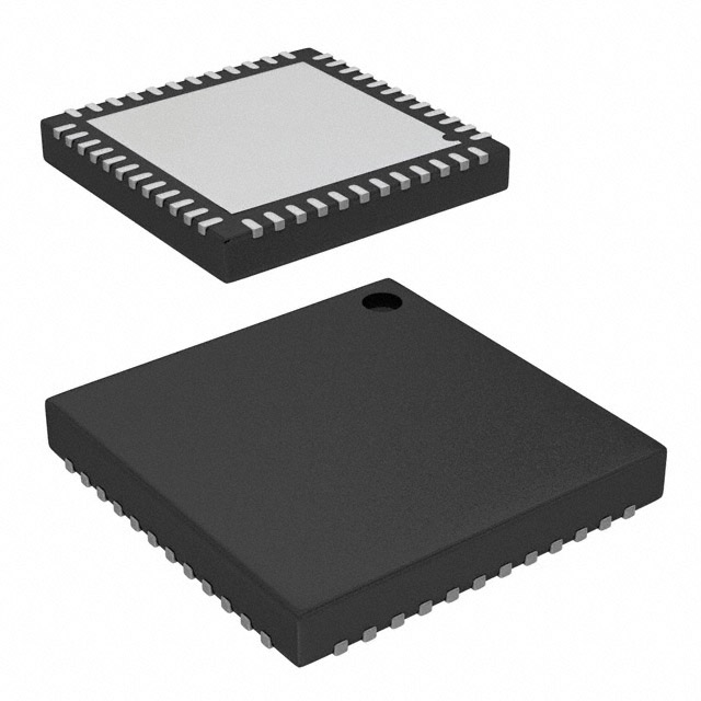
- Part No.:
- ADAR7251WBCSZ-RL
- Manufacturer:
- Analog Devices Inc.
- Category:
- Analog to Digital Converters (ADC)
- Package:
- 48-WFQFN Exposed Pad, CSP
- Datasheet:
-
 ADAR7251WBCSZ-RL.pdf
- Description:
- IC ADC 16BIT SIGMA-DELTA 48LFCSP
- Quantity:
- Payment:

- Shipping:

Inventory:1,586
Please send an inquiry. Send us your inquiry, and we will respond immediately.
Product details
Overview
ADAR7251WBCSZ-RL from Analog Devices is a 4-channel, 16-bit simultaneous-sampling continuous-time Σ-Δ ADC optimized for automotive LSR-FMCW/FSK-FMCW radar front ends. It integrates LNA, PGA (45 dB gain range in 6 dB steps), equalizer, on-chip 1.5 V reference, and PLL with 16–54 MHz input clock support. At 1.2 MSPS, it delivers 94 dB SNR, 2.4 nV/√Hz input-referred noise at max gain, and −40°C to +125°C operation in a 48-lead LFCSP_SS package.
For engineers reviewing the ADAR7251WBCSZ-RL datasheet, ADAR7251WBCSZ-RL pinout, ADAR7251WBCSZ-RL application, or ADAR7251WBCSZ-RL equivalent, key selection criteria include simultaneous 4-channel acquisition timing, FSK mode support for radar ramp synchronization, channel-to-channel phase mismatch ≤0.04°, and integrated digital interface flexibility (serial/parallel/PPI) with SPI control and GPIOs.
Technical Context
The ADAR7251WBCSZ-RL implements four independent analog signal chains, each comprising a low-noise amplifier, programmable-gain amplifier, configurable equalizer (four corner frequencies: 32–54 kHz), multibit Σ-Δ modulator, and decimation filter. Its continuous-time architecture eliminates need for external antialiasing filters and driver op amps.
It features dual-domain clocking: an internal PLL accepts 16–54 MHz master clock (MCLKIN) and generates 115.2 MHz internal clock; conversion timing is synchronized via CONV_START and DATA_READY signals for precise FSK-FMCW radar ramp alignment. The auxiliary 8-bit ADC supports 112.5–450 kHz sampling for auxiliary monitoring tasks.
Key Specifications
| Parameter | Value and Actual Design Meaning |
|---|---|
| Resolution & Channels | 16-bit, 4-channel simultaneous sampling - enables coherent multi-antenna radar processing without inter-channel skew. |
| Sample Rate Range | 300 kSPS to 1.8 MSPS - supports scalable radar resolution from short-range to mid-range detection. |
| Input-Referred Noise | 2.4 nV/√Hz at 100 kHz, 45 dB PGA gain - ensures high sensitivity for weak MMIC radar echoes. |
| SNR / SFDR | 94 dB typical SNR, 82 dB SFDR at 100 kHz - preserves dynamic range for detecting small targets amid clutter. |
| Channel Matching | ±0.5 dB interchannel gain mismatch, 0.04° phase mismatch - critical for beamforming accuracy in MIMO radar. |
| Equalizer Configurability | 4 programmable corner frequencies (32–54 kHz) - compensates for MMIC group delay roll-off in L-band radar bands. |
| Interface Modes | Serial (SPI-controlled), parallel byte-wide PPI, and FSK-sync mode - simplifies integration with TI C6000 DSPs or Arm-based radar SoCs. |
Pinout & Package
ADAR7251WBCSZ-RL is housed in a 48-lead, 7 mm × 7 mm, 0.25 mm pitch LFCSP_SS package with exposed thermal pad requiring solder connection to PCB ground plane per JEDEC JESD51 standards (θJA = 25°C/W).
| Pin/Terminal | Circuit Role | Design Meaning |
|---|---|---|
| AIN1P–AIN4N (Pins 2–5, 32–35) | Differential analog inputs | Four matched pairs accepting ±31 mV to ±5.6 V p-p full-scale based on PGA gain setting - direct interface to MMIC outputs without external amplification. |
| CONV_START (Pin 35) | Active-low conversion trigger | Synchronizes all four ADC channels to external radar ramp generator - essential for FSK-FMCW time-of-flight coherence. |
| DATA_READY (Pin 22) | Conversion completion flag | Indicates valid data ready on ADC_DOUTx lines - used by host processor to initiate DMA transfer or interrupt service. |
| SCLK_ADC / FS_ADC (Pins 34, 33) | Serial clock & frame sync | Supports both master (ADC-driven) and slave (host-driven) timing modes - enables flexible clock domain bridging in heterogeneous radar systems. |
| SPI_MOSI/MISO/CLK/SS (Pins 39–41, 38) | SPI configuration interface | 8-bit register map access for real-time gain, filter, decimation, and fault mask control - no external I²C or UART required. |
| FAULT (Pin 42) | Fault status output | Open-drain active-high signal indicating ASIL-B detectable errors (e.g., CRC failure, PLL unlock, overtemperature) - feeds directly into MCU safety monitor. |
Key Features
| Feature | Design Value |
|---|---|
| Integrated LNA + PGA front end | 45 dB programmable gain in 6 dB steps eliminates need for discrete gain stages and reduces BOM count in radar AFE designs. |
| On-chip 1.5 V reference | Stable internal reference with <10 ppm/°C drift removes dependency on external precision voltage references and associated layout complexity. |
| FSK mode support | Hardware-level synchronization of CONV_START and DATA_READY enables deterministic latency for frequency-hopping radar waveforms. |
| ASIL-B ready register protection | CRC-protected register map, error masking, and fault reporting registers meet ISO 26262 functional safety requirements for automotive LSR systems. |
| Dual supply domains | Separate AVDD (3.3 V), DVDD (1.8 V), and IOVDD (3.3 V) rails allow independent power sequencing and noise isolation between analog, digital core, and interface logic. |
Applications
| Automotive Long-Range Radar (LRR) | Short-Range Radar (SRR) |
|---|---|
|
Use Scenario: 77 GHz radar transceiver with four receive channels for adaptive cruise control and automatic emergency braking. IC Role / Device Role / Timing Role: Simultaneous digitization of quadrature IF outputs from MMICs; synchronized conversion start ensures phase-coherent sampling across antennas. Use Value: 0.04° interchannel phase mismatch enables <0.1° azimuth resolution in beamforming algorithms at 1.2 MSPS. |
Use Scenario: Blind-spot detection and cross-traffic alert using 24 GHz radar modules with compact PCB area constraints. IC Role / Device Role / Timing Role: Low-noise analog front-end ADC replacing discrete op-amp + filter + SAR ADC chain; integrated equalizer compensates for MMIC bandwidth roll-off. Use Value: 2.4 nV/√Hz input noise at 100 kHz allows detection of sub-meter objects at >30 m range with single-chip solution. |
| Radar-in-Cabin Monitoring | Industrial Level Sensing |
|
Use Scenario: Occupant detection and vital sign monitoring (respiration/heartbeat) using ultra-low-power 60 GHz radar. IC Role / Device Role / Timing Role: High-SNR digitization of micro-Doppler signatures; auxiliary 8-bit ADC monitors supply rail health during sleep-mode operation. Use Value: 94 dB SNR and 82 dB SFDR preserve spectral fidelity of <1 Hz physiological signals buried in wideband RF noise. |
Use Scenario: Non-contact liquid level measurement in chemical tanks using FMCW radar under harsh industrial temperatures. IC Role / Device Role / Timing Role: Automotive-qualified ADC operating from −40°C to +125°C; on-chip PLL tolerates wide-input-clock jitter from industrial crystal oscillators. Use Value: Qualified per AEC-Q100 Grade 1 and supported by Analog Devices' automotive longevity program - guarantees 15+ year supply continuity. |
Equivalent & Alternatives
The following parts are listed as comparable options for similar radar analog front-end ADC applications.
| Alternative Part | Technical Difference | Application Difference | Selection Advice |
|---|---|---|---|
| ADAR7252WBCSZ-RL | Same pinout, identical architecture, but supports 2.4 MSPS max sample rate and adds 12-bit auxiliary ADC with 1 MSPS capability. | Better suited for higher-resolution radar imaging where oversampling improves range resolution beyond 1.8 MSPS limit. | Select ADAR7252WBCSZ-RL only if system requires >1.8 MSPS or enhanced auxiliary monitoring bandwidth. |
| ADS131M04IPBSR | 4-channel, 24-bit delta-sigma ADC; no integrated LNA/PGA/equalizer; requires external signal conditioning; SPI-only interface; −40°C to +125°C rated. | Targeted at high-precision industrial DAQ, not radar-specific; lacks FSK sync, CONV_START, or ASIL-B register protection. | Choose ADS131M04IPBSR only for non-radar, high-DC-accuracy applications where noise floor <100 nV/√Hz suffices and external gain stages are acceptable. |
Compared with ADAR7251WBCSZ-RL, the ADAR7252WBCSZ-RL extends sample rate headroom while maintaining full compatibility, whereas the ADS131M04IPBSR trades radar-optimized features for general-purpose precision-making ADAR7251WBCSZ-RL the optimal balance of integration, timing determinism, and automotive qualification for LSR/SRR systems.
Availability
ADAR7251WBCSZ-RL is available at Aetrix Electronics and suitable for automotive radar systems, industrial FMCW sensors, and high-reliability data acquisition systems requiring stable component supply, long-term lifecycle assurance, and AEC-Q100-compliant performance.
Supply support for ADAR7251WBCSZ-RL includes scheduled delivery planning, volume procurement assistance, BOM continuity management, traceable sourcing, and lifecycle availability coordination for OEM customers, industrial embedded developers, connected-device designers, and electronics production programs.
Manufacturer
Analog Devices, Inc. is a global leader in high-performance analog, mixed-signal, and digital signal processing semiconductors, headquartered in Norwood, MA, with design centers worldwide and ISO/TS 16949-certified manufacturing.
The ADAR7251WBCSZ-RL belongs to Analog Devices' ADAR radar AFE product line, engineered specifically for automotive and industrial millimeter-wave radar systems requiring simultaneous multi-channel acquisition, ultra-low noise, and functional safety compliance.
FAQ
What is the maximum sample rate supported by the ADAR7251WBCSZ-RL?
The ADAR7251WBCSZ-RL supports programmable sample rates from 300 kSPS up to 1.8 MSPS across all four channels simultaneously. This maximum rate is achieved with decimation ratio = 48 and internal PLL enabled. At 1.8 MSPS, the input signal bandwidth reaches 900 kHz, enabling high-resolution range profiling in FMCW radar applications.
Does the ADAR7251WBCSZ-RL require an external clock source or can it operate with its internal oscillator?
The ADAR7251WBCSZ-RL supports both configurations: it can accept an external 16–54 MHz single-ended clock on the XIN/MCLKIN pin, or drive an external crystal (typically 19.2 MHz) between XIN and XOUT pins for internal oscillator operation. The internal PLL then generates the required 115.2 MHz core clock - no external oscillator IC is needed.
How does the ADAR7251WBCSZ-RL achieve channel-to-channel phase matching below 0.04 degrees?
The ADAR7251WBCSZ-RL achieves <0.04° interchannel phase mismatch through matched analog front-end layouts, laser-trimmed capacitor arrays in the Σ-Δ modulators, and common-clock distribution across all four signal paths. This matching is characterized and guaranteed over −40°C to +125°C, making it suitable for beamforming in MIMO radar architectures.
Can the ADAR7251WBCSZ-RL be used without the integrated LNA and PGA stages?
Yes - the ADAR7251WBCSZ-RL allows bypassing of both LNA and PGA via register control, enabling direct connection of conditioned signals with full-scale differential input ranges from ±31 mV (45 dB gain) up to ±5.6 V (0 dB gain). This flexibility supports reuse in legacy signal chains or hybrid AFE designs with external gain blocks.
Is the ADAR7251WBCSZ-RL qualified for automotive applications and what safety features does it include?
Yes - the ADAR7251WBCSZ-RL is AEC-Q100 Grade 1 qualified (−40°C to +125°C) and includes ASIL-B-ready features: CRC-protected register map, dedicated fault output (FAULT pin), error masking registers, and ASIL error flag/code reporting. These enable integration into ISO 26262-compliant radar ECUs without external safety monitors.
ADAR7251WBCSZ-RL Specifications
- Product attributes
- Attribute value
- Manufacturer:
- Analog Devices Inc.
- Series:
- -
- Package/Case:
- 48-WFQFN Exposed Pad, CSP
- Packaging:
- Tape & Reel (TR)
- Product Status:
- Active
- Number of Bits:
- 16
- Sampling Rate (Per Second):
- 1.8M
- Number of Inputs:
- 4
- Input Type:
- Differential
- Data Interface:
- SPI, Parallel
- Configuration:
- PGA-ADC
- Ratio - S/H:ADC:
- -
- Number of A/D Converters:
- 4
- Architecture:
- Sigma-Delta
- Reference Type:
- Internal
- Voltage - Supply, Analog:
- 2.97V ~ 3.6V
- Voltage - Supply, Digital:
- 1.62V ~ 1.98V
- Features:
- PGA, Simultaneous Sampling
- Operating Temperature:
- -40°C ~ 125°C
- Supplier Device Package:
- 48-LFCSP-SS (7x7)
- Mounting Type:
- Surface Mount
- Grade:
- Automotive
- Qualification:
- -
ADAR7251WBCSZ-RL FAQ
1.How can I place an order for ADAR7251WBCSZ-RL through Aetrix?
Please submit a Request for Quotation (RFQ) for ADAR7251WBCSZ-RL on Aetrix. Our sales agent will provide a competitive quotation and guide you through the order confirmation once you accept the terms.
2.Are the price and stock information for ADAR7251WBCSZ-RL reliable?
The price and inventory of ADAR7251WBCSZ-RL are updated periodically and may fluctuate due to market conditions. Stock and pricing data are typically refreshed every 24 hours. Quotation validity for ADAR7251WBCSZ-RL is usually 5 days.
3.What payment methods are accepted for ADAR7251WBCSZ-RL?
We accept Wire Transfer, PayPal, Credit Card, Western Union, MoneyGram, and Escrow for ADAR7251WBCSZ-RL transactions.
Note: Certain payment methods may incur a processing fee.
4.How is shipping managed for ADAR7251WBCSZ-RL?
ADAR7251WBCSZ-RL orders can be shipped via leading logistics carriers, including DHL, UPS, FedEx, TNT, or Registered Mail.
Once your ADAR7251WBCSZ-RL order is processed, you will receive an email with the shipment details and tracking number.
Note: Tracking information may take up to 24 hours to appear. Express delivery typically takes 3–5 business days.
5.How can I obtain technical support or documentation for ADAR7251WBCSZ-RL?
For technical support, including ADAR7251WBCSZ-RL datasheets, pinout diagrams, or application guidance, please contact our engineering support team. They can provide detailed documentation and assistance for your ADAR7251WBCSZ-RL requirements.
6.How does Aetrix verify that ADAR7251WBCSZ-RL is sourced from the original manufacturer or authorized distributors?
All ADAR7251WBCSZ-RL products on Aetrix are procured from qualified distributors and authorized channels. Our dedicated quality assurance team conducts strict verification, including traceability checks and, if necessary, third-party testing. This ensures that ADAR7251WBCSZ-RL meets industry standards.
7.What is the process for return or replacement of ADAR7251WBCSZ-RL?
All ADAR7251WBCSZ-RL units undergo pre-shipment inspection (PSI). If there is an issue with ADAR7251WBCSZ-RL, returns or replacements are accepted under the following conditions:
1.Quantity discrepancies, incorrect items, or visible external defects (such as breakage or corrosion), acknowledged by Aetrix.
2.The issue is reported within 90 days of delivery.
3.The ADAR7251WBCSZ-RL part is unused and in its original packaging.
Return procedure for ADAR7251WBCSZ-RL:
1.Submit a request within 90 days.
2.Obtain a Return Material Authorization (RMA) from Aetrix.
ADAR7251WBCSZ-RL Tags
-
ADC081C021CIMKX/NOPB
Texas Instruments

-
MCP3021A5T-E/OT
Microchip Technology
-
TLA2024IRUGR
Texas Instruments
-
MCP3221A5T-E/OT
Microchip Technology
-
MCP3221A5T-I/OT
Microchip Technology
-
MCP3221A4T-E/OT
Microchip Technology
-
MCP3221A6T-E/OT
Microchip Technology
-
MCP3221A0T-E/OT
Microchip Technology
-
MCP3221A1T-E/OT
Microchip Technology

-
ADC121S021CIMFX/NOPB
Texas Instruments

-
MCP3001-I/MS
Microchip Technology

-
MCP3001-I/SN
Microchip Technology
Tech Hub

A practical engineering guide to 3.3V and 5V logic compatibility, input thresholds, resistor dividers, translator ICs, MOSFET level shifting, I2C pull-ups, timing limits and power-sequencing risks.

The 74HC595 uses push-pull logic outputs, while the TPIC6B595 uses 50 V open-drain DMOS sinks for higher-power loads. This guide compares timing, current limits, 3.3 V interfacing, load wiring, thermal…

The 74HC595 converts serial data into eight stable parallel outputs. This guide covers pin functions, shift and storage timing, OE and MR behavior, drive-current limits, cascading, voltage compatibilit…

A technical comparison of level-sensitive latches and edge-triggered flip-flops, covering timing windows, setup and hold limits, master–slave operation, time borrowing, race-through, HDL inference and…

A D latch stores one bit while Enable controls when data can pass. This reference covers gate-level operation, truth tables, transparency, setup and hold timing, LE versus OE, common ICs and practical …

An SR latch stores one bit through cross-coupled feedback. This engineering reference covers NOR and NAND implementations, truth tables, forbidden-state recovery, gated operation, switch debouncing, fa…

Latch circuits retain one bit through feedback. This technical reference covers SR and D latches, truth tables, transparency, timing limits, latch-versus-flip-flop behavior, applications and common log…

An engineering guide to LED driver operation, constant-current and constant-voltage outputs, linear and switching topologies, dimming, IC selection, calculations, replacement compatibility, and fault c…

Operational amplifier guide covering op amp basics, feedback, ideal vs real op amps, common configurations, buffer circuits, offset, bias current, gain-bandwidth, slew rate, rail-to-rail limits and sel…

Jumper cables guide covering safe connection order, red and black clamp placement, final ground connection, cable gauge, length, clamp quality, copper vs CCA cables, jump starter comparison and battery…


