
 My Inquiry
 My Account


Analog Devices Inc. ADDI7004BBCZRL
- Part No.:
- ADDI7004BBCZRL
- Manufacturer:
- Analog Devices Inc.
- Category:
- Video Processing
- Package:
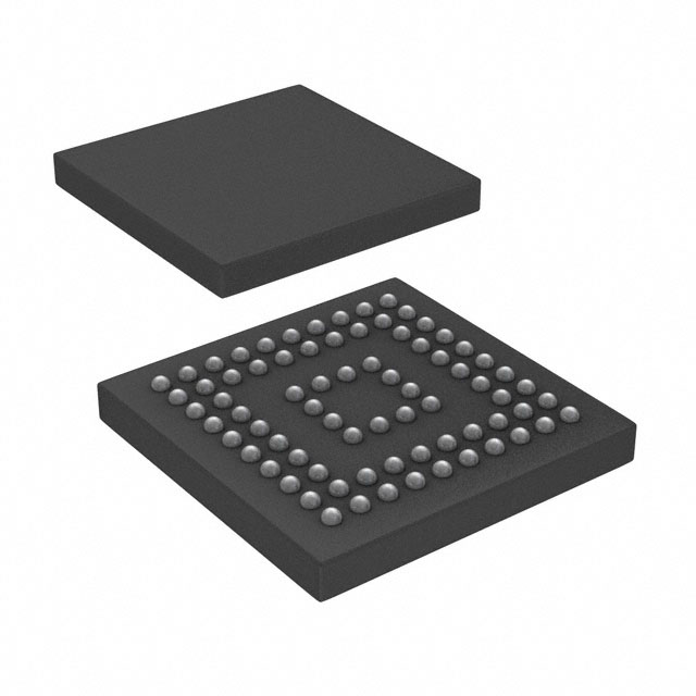
- 76-LFBGA, CSPBGA
- Datasheet:
-
 ADDI7004BBCZRL.pdf
- Description:
- IC VID HD IMAG SGN PROC 76CSPBGA
- Quantity:
- Payment:

- Shipping:

Inventory:2,779
Please send an inquiry. Send us your inquiry, and we will respond immediately.
Product details
Overview
ADDI7004BBCZRL from Analog Devices is a quad-channel HD image signal processor with integrated analog front ends (AFE), 14-bit 72 MHz ADCs, precision timing core (220 ps resolution at 72 MHz), and reduced-range LVDS serial output-designed for high-speed imaging systems requiring synchronized multi-sensor capture in digital video cameras, medical imaging, and industrial inspection.
For engineers reviewing the ADDI7004BBCZRL datasheet, ADDI7004BBCZRL pinout, ADDI7004BBCZRL application, or ADDI7004BBCZRL equivalent, key selection criteria include channel count (4), ADC resolution (14-bit), pixel clock support (up to 72 MHz), CDS/SHA timing resolution (220 ps), and differential analog input compatibility with CCD/CMOS sensors.
Technical Context
The ADDI7004BBCZRL implements four identical analog front-end channels, each integrating black level clamp, configurable CDS or SHA, 10-bit VGA (6 dB–42 dB gain), and a 14-bit ADC operating at up to 72 MHz. All channels share a common Precision Timing™ core enabling sub-220 ps clock edge adjustment for correlated double sampling and sample-and-hold control.
It uses a 3-wire serial interface (SDATA/SCK/CLI) for register programming and outputs dual-channel reduced-range LVDS data (8 differential pairs: DOUT0P/N through DOUT7P/N). The device operates from a single 1.8 V analog/digital core supply and supports differential analog inputs with selectable gain settings (−3 dB, 0 dB, +3 dB, +6 dB).
Key Specifications
| Parameter | Value and Actual Design Meaning |
|---|---|
| Channel Count | 4 independent AFE channels, enabling simultaneous processing of quadruple sensor streams or spatially multiplexed imaging paths. |
| ADC Resolution & Rate | 14-bit, 72 MHz sampling-supports HD/Full HD pixel rates (e.g., 1920×1080 @ 60 fps raw) with >85 dB SNR. |
| Precision Timing Resolution | 220 ps at 72 MHz-enables sub-pixel-level CDS/SHA clock alignment critical for low-noise CCD readout. |
| VGA Gain Range | 6 dB to 42 dB in 10-bit steps-provides fine-grained analog gain control before digitization to maximize dynamic range utilization. |
| Analog Supply Voltage | 1.8 V core supply-reduces power consumption and thermal load in compact, high-density imaging modules. |
| Digital Output Interface | Reduced-range LVDS (8 differential pairs)-low EMI, high-speed serial output compatible with FPGA/CPLD receivers without termination resistors. |
Pinout & Package
Package: 6 mm × 6 mm, 76-ball BGA (ball pitch: 0.5 mm), RoHS-compliant, rated for −40°C to +85°C operation.
| Pin/Terminal | Circuit Role | Design Meaning |
|---|---|---|
| INP_A / INM_A through INP_D / INM_D | Differential analog inputs (4 channels) | Accepts fully differential CCD/CMOS sensor outputs; supports CDS or SHA configuration per channel. |
| DOUT0P/DOUT0N – DOUT7P/DOUT7N | LVDs data output pairs (8 total) | Serializes 4-channel 14-bit pixel data into two parallel LVDS lanes (dual-channel mode); reduced swing lowers power and EMI. |
| TCLK0P/TCLK0N, TCLK1P/TCLK1N | Precision Timing core clock outputs | Deliver phase-adjustable clocks (220 ps resolution) to external CDS/SHA circuits or sensor timing controllers. |
| SDATA, SCK, CLI | 3-wire serial interface | Configures internal registers (gain, clamp level, timing offsets); no I²C/SPI required-minimizes host interface complexity. |
| RSTB, SL | Hardware reset and sleep control | Asynchronous active-low reset (RSTB) and sleep enable (SL) allow deterministic initialization and low-power standby modes. |
Key Features
| Feature | Design Value |
|---|---|
| Quad identical AFE channels | Enables scalable multi-sensor architectures (e.g., stereo, multi-angle, or tiled sensor arrays) without inter-channel calibration drift. |
| 220 ps timing resolution at 72 MHz | Permits precise CDS/SHA clock skew correction across all four channels-critical for eliminating fixed-pattern noise in scientific CCDs. |
| Selectable CDS or SHA configuration | Supports both CCD (CDS) and CMOS (SHA) sensor types within same hardware platform-reducing BOM and design reuse effort. |
| 1.8 V single-supply operation | Eliminates need for separate analog/digital rails-simplifies power delivery and reduces PCB layer count in space-constrained camera modules. |
| Reduced-range LVDS interface | Operates at ~350 mV differential swing-halves power vs. standard LVDS and enables direct connection to Xilinx/Intel FPGA banks without external terminations. |
Applications
| Digital Video Cameras | Medical Imaging Systems |
|---|---|
Use Scenario: High-frame-rate HD video capture in broadcast or machine vision cameras using four synchronized global-shutter CMOS sensors. IC Role / Device Role / Timing Role: Quad-channel AFE and ADC hub synchronizing pixel data acquisition, applying real-time black-level correction and variable gain prior to LVDS serialization. Use Value: Enables 4×1080p60 uncompressed video streaming over two LVDS lanes with <220 ps inter-channel timing skew-preserving temporal fidelity for motion analysis. | Use Scenario: Digital X-ray or endoscopic imaging requiring low-noise, high-dynamic-range capture from linear or area CCD arrays. IC Role / Device Role / Timing Role: Precision-timed CDS processor with 14-bit digitization and programmable clamp-suppressing reset noise and offset drift in low-light diagnostic imaging. Use Value: Achieves >85 dB SNR and <0.5 LSB INL via 220 ps CDS clock alignment-meeting IEC 62220-1-1 requirements for clinical image quality. |
| High-Speed Industrial Cameras | Scientific Imaging Instruments |
Use Scenario: Real-time defect detection on fast-moving production lines using time-delay integration (TDI) or burst-mode line-scan sensors. IC Role / Device Role / Timing Role: Four-channel timing-coordinated AFE capturing synchronized line data with sub-pixel clock accuracy for pixel registration. Use Value: Supports 72 MHz pixel rate with deterministic 220 ps timing adjustment-enabling <1 µm spatial registration accuracy at 10 m/s conveyor speeds. | Use Scenario: Low-light fluorescence microscopy or spectroscopy using back-illuminated CCDs requiring ultra-low-noise analog signal conditioning. IC Role / Device Role / Timing Role: Precision CDS processor with variable gain and black-level clamp-optimizing dynamic range while suppressing kTC noise before 14-bit digitization. Use Value: Delivers <2.5 e⁻ RMS read noise (typ.) at 6 dB gain and 72 MHz-enabling single-photon-level sensitivity in photon-starved applications. |
Equivalent & Alternatives
The following parts are listed as comparable options for similar quad-channel image signal processor applications.
| Alternative Part | Technical Difference | Application Difference | Selection Advice |
|---|---|---|---|
| ADDI7005BBCZRL | Same package and pinout; adds SPI interface alongside 3-wire serial; identical AFE/ADC specs and timing core. | Preferred when host MCU requires SPI-native register access or firmware update capability without protocol translation. | Select ADDI7005BBCZRL only if SPI interface is required-no benefit for pure 3-wire designs; same cost and availability profile. |
| ISLA214P50IRZ | Single-channel, 14-bit, 500 MSPS ADC; no integrated AFE, CDS, or timing core-requires external analog conditioning and clock management. | Suitable for custom high-speed digitization where AFE flexibility and timing control are handled externally. | Choose ISLA214P50IRZ only for non-standard sensor interfaces or when full AFE integration is unnecessary-adds system complexity but offers higher sample rate. |
Compared with ADDI7004BBCZRL, ADDI7005BBCZRL provides identical imaging performance with added SPI flexibility, while ISLA214P50IRZ trades integrated functionality for raw speed and design freedom-making ADDI7004BBCZRL optimal for turnkey quad-channel HD imaging where timing precision and analog integration are mandatory.
Availability
ADDI7004BBCZRL is available at Aetrix Electronics and suitable for digital video cameras, medical imaging systems, and high-speed industrial cameras requiring stable component supply, long-term lifecycle support, and guaranteed traceability for Class II medical and automotive-grade programs.
Supply support for ADDI7004BBCZRL includes scheduled delivery planning, volume procurement assistance, BOM continuity management, traceable sourcing, and lifecycle availability coordination for OEM customers, industrial embedded developers, connected-device designers, and electronics production programs.
Manufacturer
Analog Devices, Inc. is a global leader in high-performance analog, mixed-signal, and digital signal processing semiconductors, headquartered in Wilmington, MA, serving industrial, communications, automotive, and healthcare markets since 1965.
The ADDI7004BBCZRL belongs to Analog Devices' Precision Imaging Signal Processing product line-engineered specifically for high-fidelity, multi-sensor imaging systems demanding sub-nanosecond timing control, low-noise analog conditioning, and deterministic LVDS serialization.
FAQ
What is the maximum supported pixel clock frequency for the ADDI7004BBCZRL?
The ADDI7004BBCZRL supports a maximum pixel clock frequency of 72 MHz per channel. This enables full HD (1920×1080) capture at up to 60 fps with 14-bit depth in quad-channel mode. The Precision Timing™ core maintains 220 ps resolution even at this rate, ensuring accurate CDS/SHA clock alignment across all four AFEs. Each channel's ADC operates synchronously at this rate, and the reduced-range LVDS interface sustains reliable serialization without data loss.
Does the ADDI7004BBCZRL support both CCD and CMOS image sensors?
Yes, the ADDI7004BBCZRL explicitly supports both CCD and CMOS sensors via its configurable CDS or SHA architecture per channel. In CDS mode, it suppresses reset noise typical of CCDs; in SHA mode, it captures sampled pixel values suited for CMOS rolling/global shutter outputs. The differential analog inputs (INP_X/INM_X) accept standard sensor output swings, and gain settings (−3 dB to +6 dB) accommodate varying sensor output levels-making ADDI7004BBCZRL adaptable across sensor technologies without hardware change.
What is the function of the TCLK0P/TCLK0N and TCLK1P/TCLK1N pins on the ADDI7004BBCZRL?
The TCLK0P/TCLK0N and TCLK1P/TCLK1N pins on the ADDI7004BBCZRL deliver precision-adjustable clock outputs from the integrated Timing Core. These differential signals drive external CDS or SHA circuitry with 220 ps resolution at 72 MHz, enabling sub-pixel-level synchronization across multiple sensors or channels. They are not input clocks but outputs-programmable via the 3-wire interface to align sampling edges with sensor timing requirements. This eliminates need for external jitter-cleaners or delay lines in ADDI7004BBCZRL-based designs.
Is the ADDI7004BBCZRL pin-compatible with any other Analog Devices image processors?
The ADDI7004BBCZRL is pin-compatible with the ADDI7005BBCZRL-same 76-ball BGA footprint, identical power, analog input, LVDS output, and timing pin assignments. The only functional difference is that ADDI7005BBCZRL adds an SPI interface (SDIO/SCLK) alongside the existing 3-wire serial interface. No PCB redesign is needed when migrating between these two parts. However, ADDI7004BBCZRL is not pin-compatible with earlier ADDI700x variants (e.g., ADDI7003) due to differing ball counts and signal allocations.
What power supply requirements does the ADDI7004BBCZRL have?
The ADDI7004BBCZRL requires a single 1.8 V supply for both analog and digital core circuitry-no separate AVDD/DVDD rails needed. It accepts 1.8 V ±5% over the full −40°C to +85°C temperature range. Decoupling is critical: Analog Devices recommends 100 nF ceramic capacitors placed within 2 mm of each VDD ball, plus bulk capacitance (4.7 µF) per power domain. The device draws approximately 480 mW typical at 72 MHz with all four channels active-enabling thermally constrained camera module designs without forced cooling.
ADDI7004BBCZRL Specifications
- Product attributes
- Attribute value
- Manufacturer:
- Analog Devices Inc.
- Series:
- Precision Timing™
- Package/Case:
- 76-LFBGA, CSPBGA
- Packaging:
- Tape & Reel (TR)
- Product Status:
- Obsolete
- Function:
- Processor
- Applications:
- Consumer Video
- Standards:
- -
- Control Interface:
- Serial
- Voltage - Supply:
- 1.8V ~ 3V
- Mounting Type:
- Surface Mount
- Grade:
- -
- Qualification:
- -
- Supplier Device Package:
- 76-CSPBGA (6x6)
ADDI7004BBCZRL FAQ
1.How can I place an order for ADDI7004BBCZRL through Aetrix?
Please submit a Request for Quotation (RFQ) for ADDI7004BBCZRL on Aetrix. Our sales agent will provide a competitive quotation and guide you through the order confirmation once you accept the terms.
2.Are the price and stock information for ADDI7004BBCZRL reliable?
The price and inventory of ADDI7004BBCZRL are updated periodically and may fluctuate due to market conditions. Stock and pricing data are typically refreshed every 24 hours. Quotation validity for ADDI7004BBCZRL is usually 5 days.
3.What payment methods are accepted for ADDI7004BBCZRL?
We accept Wire Transfer, PayPal, Credit Card, Western Union, MoneyGram, and Escrow for ADDI7004BBCZRL transactions.
Note: Certain payment methods may incur a processing fee.
4.How is shipping managed for ADDI7004BBCZRL?
ADDI7004BBCZRL orders can be shipped via leading logistics carriers, including DHL, UPS, FedEx, TNT, or Registered Mail.
Once your ADDI7004BBCZRL order is processed, you will receive an email with the shipment details and tracking number.
Note: Tracking information may take up to 24 hours to appear. Express delivery typically takes 3–5 business days.
5.How can I obtain technical support or documentation for ADDI7004BBCZRL?
For technical support, including ADDI7004BBCZRL datasheets, pinout diagrams, or application guidance, please contact our engineering support team. They can provide detailed documentation and assistance for your ADDI7004BBCZRL requirements.
6.How does Aetrix verify that ADDI7004BBCZRL is sourced from the original manufacturer or authorized distributors?
All ADDI7004BBCZRL products on Aetrix are procured from qualified distributors and authorized channels. Our dedicated quality assurance team conducts strict verification, including traceability checks and, if necessary, third-party testing. This ensures that ADDI7004BBCZRL meets industry standards.
7.What is the process for return or replacement of ADDI7004BBCZRL?
All ADDI7004BBCZRL units undergo pre-shipment inspection (PSI). If there is an issue with ADDI7004BBCZRL, returns or replacements are accepted under the following conditions:
1.Quantity discrepancies, incorrect items, or visible external defects (such as breakage or corrosion), acknowledged by Aetrix.
2.The issue is reported within 90 days of delivery.
3.The ADDI7004BBCZRL part is unused and in its original packaging.
Return procedure for ADDI7004BBCZRL:
1.Submit a request within 90 days.
2.Obtain a Return Material Authorization (RMA) from Aetrix.
ADDI7004BBCZRL Tags
-
HDMI2C1-6C1
STMicroelectronics
-
ADA4430-1YKSZ-R7
Analog Devices Inc.

-
LM1881MX/NOPB
Texas Instruments

-
SN75DP130SSRGZR
Texas Instruments
-
EQCO30T5.2
Microchip Technology

-
LMH1980MM/NOPB
Texas Instruments
-
EQCO30R5.D
Microchip Technology

-
SII9022ACNU
Lattice Semiconductor Corporation
-
SN65DP159RGZR
Texas Instruments

-
SN65DP159RSBR
Texas Instruments
-
SN65DP141RLJR
Texas Instruments
-
LMH0303SQ/NOPB
Texas Instruments
Tech Hub

A practical engineering guide to 3.3V and 5V logic compatibility, input thresholds, resistor dividers, translator ICs, MOSFET level shifting, I2C pull-ups, timing limits and power-sequencing risks.

The 74HC595 uses push-pull logic outputs, while the TPIC6B595 uses 50 V open-drain DMOS sinks for higher-power loads. This guide compares timing, current limits, 3.3 V interfacing, load wiring, thermal…

The 74HC595 converts serial data into eight stable parallel outputs. This guide covers pin functions, shift and storage timing, OE and MR behavior, drive-current limits, cascading, voltage compatibilit…

A technical comparison of level-sensitive latches and edge-triggered flip-flops, covering timing windows, setup and hold limits, master–slave operation, time borrowing, race-through, HDL inference and…

A D latch stores one bit while Enable controls when data can pass. This reference covers gate-level operation, truth tables, transparency, setup and hold timing, LE versus OE, common ICs and practical …

An SR latch stores one bit through cross-coupled feedback. This engineering reference covers NOR and NAND implementations, truth tables, forbidden-state recovery, gated operation, switch debouncing, fa…

Latch circuits retain one bit through feedback. This technical reference covers SR and D latches, truth tables, transparency, timing limits, latch-versus-flip-flop behavior, applications and common log…

An engineering guide to LED driver operation, constant-current and constant-voltage outputs, linear and switching topologies, dimming, IC selection, calculations, replacement compatibility, and fault c…

Operational amplifier guide covering op amp basics, feedback, ideal vs real op amps, common configurations, buffer circuits, offset, bias current, gain-bandwidth, slew rate, rail-to-rail limits and sel…

Jumper cables guide covering safe connection order, red and black clamp placement, final ground connection, cable gauge, length, clamp quality, copper vs CCA cables, jump starter comparison and battery…


