
 My Inquiry
 My Account


Analog Devices Inc. ADF4113BCPZ-RL7
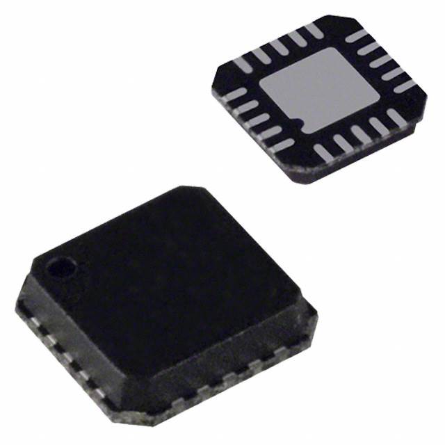
- Part No.:
- ADF4113BCPZ-RL7
- Manufacturer:
- Analog Devices Inc.
- Package:
- 20-WFQFN Exposed Pad, CSP
- Datasheet:
-
 ADF4113BCPZ-RL7.pdf
- Description:
- IC CLK/FREQ SYNTH 20LFCSP
- Quantity:
- Payment:

- Shipping:

Inventory:4,807
Please send an inquiry. Send us your inquiry, and we will respond immediately.
Product details
Overview
ADF4113BCPZ-RL7 from Analog Devices is a 4.0 GHz RF PLL frequency synthesizer IC used as a local oscillator in wireless transceivers. It features a dual-modulus prescaler (8/9, 16/17, 32/33, 64/65), programmable charge pump current up to 5 mA, 3-wire serial interface, and operates from 2.7 V to 5.5 V. It enables precise frequency synthesis in GSM, WCDMA, and wireless LAN base station transmitters.
For engineers reviewing the ADF4113BCPZ-RL7 datasheet, ADF4113BCPZ-RL7 pinout, ADF4113BCPZ-RL7 application, or ADF4113BCPZ-RL7 equivalent, key selection considerations include its 4.0 GHz RF input range, 200 MHz maximum prescaler output frequency at 5 V, −91 dBc/Hz phase noise at 900 MHz (1 kHz offset), lock detect capability, and LFCSP-20 package with exposed paddle grounded to AGND.
Technical Context
The ADF4113BCPZ-RL7 implements a digital phase frequency detector (PFD) with precision charge pump, 14-bit R counter, 6-bit A counter, and 13-bit B counter driving a dual-modulus prescaler (P/P+1) to realize N = BP + A division. Its architecture supports wideband PLL design with external loop filter and VCO integration.
It provides analog and digital lock detection, hardware/software power-down modes, and programmable antibacklash pulse width. The separate VP supply (up to 6.0 V) extends tuning voltage headroom in 3 V systems, enabling wider VCO tuning ranges without level-shifting.
Key Specifications
| Parameter | Value and Actual Design Meaning |
|---|---|
| RF Input Frequency | 0.2 GHz to 4.0 GHz - supports full-band operation up to cellular and WLAN upper bands with −5 dBm input sensitivity. |
| Max Prescaler Output Freq | 200 MHz at 5 V - constrains prescaler selection to ensure CMOS counters operate within safe timing margins. |
| Charge Pump Current | Programmable up to 5 mA via RSET - sets loop filter gain and impacts lock time and reference spur suppression. |
| PFD Max Frequency | 55 MHz - determines maximum reference comparison rate and influences phase noise floor and spurious performance. |
| Phase Noise @ 900 MHz | −91 dBc/Hz at 1 kHz offset - enables high-sensitivity receivers requiring low close-in phase jitter. |
| Supply Voltage Range | 2.7 V to 5.5 V for AVDD/DVDD; VP ≥ AVDD up to 6.0 V - allows independent tuning voltage rail for extended VCO range. |
| Power Consumption | 11 mA max at 3 V - balances RF performance with power efficiency in battery-sensitive or thermally constrained designs. |
Pinout & Package
ADF4113BCPZ-RL7 uses a 20-lead LFCSP (4 mm × 4 mm, 0.5 mm pitch) with exposed paddle soldered to AGND for thermal and electrical integrity.
| Pin/Terminal | Circuit Role | Design Meaning |
|---|---|---|
| RSET | Charge pump current setting | Resistor to CPGND sets ICPmax; 4.7 kΩ yields 5 mA - directly configures loop dynamics and stability margin. |
| CP | Charge pump output | Drives external loop filter; ±ICP sourcing/sinking - forms critical control path to VCO tuning voltage. |
| CPGND | Charge pump ground return | Dedicated low-noise ground for CP - prevents coupling of digital switching noise into sensitive analog control path. |
| RFINA / RFINB | Differential RF input | AC-coupled inputs to prescaler - require 100 pF bypass and impedance matching for optimal 4 GHz signal integrity. |
| REFIN | Reference clock input | CMOS input biased at DVDD/2; 5–104 MHz range - accepts crystal oscillator or buffered clock with 0.4–DVDD Vp-p. |
| DATA / CLK / LE | 3-wire serial interface | 24-bit shift register control - enables dynamic reconfiguration of N, R, A, B counters and mode bits during operation. |
| MUXOUT | Multiplexed diagnostic output | Selectable lock detect, scaled RF, or scaled REFIN - supports real-time PLL status monitoring without external probes. |
| CE | Chip enable | Active-low global power-down - places CP in high-Z and disables internal logic to reduce quiescent current to 1 µA. |
Key Features
| Feature | Design Value |
|---|---|
| Dual-modulus prescaler | Configurable 8/9, 16/17, 32/33, or 64/65 ratio - enables wide N-divider range while maintaining PFD frequency above 55 MHz. |
| Separate VP supply | VP ≥ AVDD up to 6.0 V - decouples charge pump headroom from core supply, supporting 0–6 V VCO tuning without external regulators. |
| Programmable antibacklash pulse | Adjustable width minimizes dead-zone-induced reference spurs - improves spectral purity in narrow-loop-bandwidth applications. |
| Analog + digital lock detect | Dual lock indicators with configurable thresholds - enables robust system-level synchronization verification in safety-critical or burst-mode radios. |
| Low-power sleep mode | 1 µA typical quiescent current - supports rapid wake-up in TDD systems or power-gated RF front-ends without losing register state. |
Applications
| Base Station Transmitter LO | Wireless Handset Local Oscillator |
|---|---|
Use Scenario: Generating stable 1.96 GHz LO for WCDMA uplink transmitter in macrocell BTS. IC Role / Device Role / Timing Role: Core PLL synthesizer providing frequency-agile, low-phase-noise LO synchronized to 10 MHz network reference. Use Value: −85 dBc/Hz phase noise at 1 kHz offset ensures ACLR compliance; 4.0 GHz range covers all cellular bands without external dividers. | Use Scenario: Dual-band LO generation (836 MHz / 1960 MHz) in GSM/WCDMA handset RF transceiver. IC Role / Device Role / Timing Role: Programmable frequency source enabling band-switching and carrier aggregation with fast lock time (~200–400 µs). Use Value: Hardware power-down reduces standby current; 3-wire interface allows seamless reprogramming during handover. |
| Wireless LAN Access Point | Communications Test Equipment |
Use Scenario: 5.2–5.8 GHz LO synthesis in 802.11a/n/ac AP using external active doubler. IC Role / Device Role / Timing Role: High-frequency reference generator feeding multiplier chain; supports fine channel spacing (5 MHz) via programmable R/N dividers. Use Value: 200 MHz max prescaler output allows use of 64/65 prescaler at 5.2 GHz input, preserving PFD frequency >20 MHz for low spurs. | Use Scenario: Agile LO in vector signal analyzer requiring rapid frequency hopping and low residual phase noise. IC Role / Device Role / Timing Role: Precision frequency synthesizer with lock detect feedback to host controller for measurement synchronization. Use Value: MUXOUT-selectable lock detect enables automated calibration sequences; −215 dBc/Hz normalized phase noise floor supports high-dynamic-range analysis. |
Equivalent & Alternatives
The following parts are listed as comparable options for similar RF PLL synthesizer applications.
| Alternative Part | Technical Difference | Application Difference | Selection Advice |
|---|---|---|---|
| ADF4153AACPZ-RL7 | Integrated VCO (6.3–6.8 GHz); higher PFD frequency (110 MHz); no external prescaler needed. | Eliminates external VCO and loop filter components; targets higher-frequency bands only. | Choose when system requires single-chip solution above 6 GHz and board space is constrained. |
| HMC703LP4E | Wider RF range (0.1–13 GHz); integrated fractional-N divider; higher max PFD (150 MHz). | Supports fractional-N synthesis for finer resolution and faster settling; requires different register mapping. | Choose for applications needing sub-Hz frequency resolution or multi-GHz coverage without prescaler configuration. |
Compared with ADF4113BCPZ-RL7, ADF4153AACPZ-RL7 integrates the VCO but sacrifices flexibility below 6 GHz, while HMC703LP4E offers broader bandwidth and fractional-N capability at the cost of increased complexity and layout sensitivity.
Availability
ADF4113BCPZ-RL7 is available at Aetrix Electronics and suitable for wireless infrastructure, handheld radio, and test equipment applications requiring stable component supply, long-term lifecycle support, and RoHS-compliant packaging.
Supply support for ADF4113BCPZ-RL7 includes scheduled delivery planning, volume procurement assistance, BOM continuity management, traceable sourcing, and lifecycle availability coordination for OEM customers, industrial embedded developers, connected-device designers, and electronics production programs.
Manufacturer
Analog Devices is a global leader in high-performance analog, mixed-signal, and RF ICs, serving communications, industrial, and automotive markets with precision signal processing solutions.
The ADF411x family was designed specifically for cost-sensitive, high-volume wireless infrastructure and handset applications requiring robust PLL performance, low power, and flexible programmability in compact packages.
FAQ
What is the maximum RF input frequency supported by the ADF4113BCPZ-RL7?
The ADF4113BCPZ-RL7 supports an RF input frequency range of 0.2 GHz to 4.0 GHz when driven at −5 dBm. At lower input levels (e.g., −10 dBm), the upper limit is 3.7 GHz. This 4.0 GHz rating enables direct synthesis for LTE Band 41, WiMAX, and unlicensed 5 GHz bands using external prescaling or doubling techniques.
How does the separate VP supply improve VCO tuning range in ADF4113BCPZ-RL7 designs?
The ADF4113BCPZ-RL7's VP pin accepts up to 6.0 V independently of AVDD/DVDD (2.7–5.5 V), allowing the charge pump to generate a 0–6 V tuning voltage. This eliminates need for external op-amps or DC-DC boosters in 3 V systems, directly supporting wide-tuning VCOs like those used in broadband wireless access equipment.
Can ADF4113BCPZ-RL7 achieve sub-100 µs lock time, and what conditions are required?
Yes - ADF4113BCPZ-RL7 achieves ~200 µs typical lock time at 900 MHz with 35 kHz loop bandwidth and 200 kHz PFD frequency. Sub-100 µs is possible with higher PFD frequencies (up to 55 MHz), optimized loop filter design, and reduced N-divider values, though phase noise and spur performance must be verified per application.
What is the function of the MUXOUT pin on ADF4113BCPZ-RL7, and how is it configured?
The MUXOUT pin on ADF4113BCPZ-RL7 outputs selectable signals - lock detect, divided RF (÷8 or ÷16), or divided reference - controlled by bits in Register 3. It provides real-time PLL status without interrupting normal operation, enabling closed-loop calibration and fault detection in base station and test equipment systems.
Does ADF4113BCPZ-RL7 support both integer-N and fractional-N synthesis?
No - ADF4113BCPZ-RL7 is an integer-N PLL synthesizer only. It lacks a sigma-delta modulator or fractional divider, so channel spacing is limited to integer multiples of the PFD frequency. For fractional-N capability, consider Analog Devices' ADF4351 or Hittite's HMC703LP4E as alternatives.
ADF4113BCPZ-RL7 Specifications
- Product attributes
- Attribute value
- Manufacturer:
- Analog Devices Inc.
- Series:
- -
- Package/Case:
- 20-WFQFN Exposed Pad, CSP
- Packaging:
- Tape & Reel (TR)
- Product Status:
- Active
- Programmable:
- Not Verified
- Type:
- Clock/Frequency Synthesizer (RF)
- PLL:
- Yes
- Input:
- CMOS, TTL
- Output:
- Clock
- Number of Circuits:
- 1
- Ratio - Input:Output:
- 2:1
- Differential - Input:Output:
- Yes/No
- Frequency - Max:
- 4GHz
- Divider/Multiplier:
- Yes/No
- Voltage - Supply:
- 2.7V ~ 5.5V
- Operating Temperature:
- -40°C ~ 85°C
- Mounting Type:
- Surface Mount
- Grade:
- -
- Qualification:
- -
- Supplier Device Package:
- 20-LFCSP (4x4)
ADF4113BCPZ-RL7 FAQ
1.How can I place an order for ADF4113BCPZ-RL7 through Aetrix?
Please submit a Request for Quotation (RFQ) for ADF4113BCPZ-RL7 on Aetrix. Our sales agent will provide a competitive quotation and guide you through the order confirmation once you accept the terms.
2.Are the price and stock information for ADF4113BCPZ-RL7 reliable?
The price and inventory of ADF4113BCPZ-RL7 are updated periodically and may fluctuate due to market conditions. Stock and pricing data are typically refreshed every 24 hours. Quotation validity for ADF4113BCPZ-RL7 is usually 5 days.
3.What payment methods are accepted for ADF4113BCPZ-RL7?
We accept Wire Transfer, PayPal, Credit Card, Western Union, MoneyGram, and Escrow for ADF4113BCPZ-RL7 transactions.
Note: Certain payment methods may incur a processing fee.
4.How is shipping managed for ADF4113BCPZ-RL7?
ADF4113BCPZ-RL7 orders can be shipped via leading logistics carriers, including DHL, UPS, FedEx, TNT, or Registered Mail.
Once your ADF4113BCPZ-RL7 order is processed, you will receive an email with the shipment details and tracking number.
Note: Tracking information may take up to 24 hours to appear. Express delivery typically takes 3–5 business days.
5.How can I obtain technical support or documentation for ADF4113BCPZ-RL7?
For technical support, including ADF4113BCPZ-RL7 datasheets, pinout diagrams, or application guidance, please contact our engineering support team. They can provide detailed documentation and assistance for your ADF4113BCPZ-RL7 requirements.
6.How does Aetrix verify that ADF4113BCPZ-RL7 is sourced from the original manufacturer or authorized distributors?
All ADF4113BCPZ-RL7 products on Aetrix are procured from qualified distributors and authorized channels. Our dedicated quality assurance team conducts strict verification, including traceability checks and, if necessary, third-party testing. This ensures that ADF4113BCPZ-RL7 meets industry standards.
7.What is the process for return or replacement of ADF4113BCPZ-RL7?
All ADF4113BCPZ-RL7 units undergo pre-shipment inspection (PSI). If there is an issue with ADF4113BCPZ-RL7, returns or replacements are accepted under the following conditions:
1.Quantity discrepancies, incorrect items, or visible external defects (such as breakage or corrosion), acknowledged by Aetrix.
2.The issue is reported within 90 days of delivery.
3.The ADF4113BCPZ-RL7 part is unused and in its original packaging.
Return procedure for ADF4113BCPZ-RL7:
1.Submit a request within 90 days.
2.Obtain a Return Material Authorization (RMA) from Aetrix.
ADF4113BCPZ-RL7 Tags

-
CD74HCT4046AM96
Texas Instruments

-
MC14046BDWR2G
onsemi

-
501MILFT
Renesas
-
CD74HC7046AM
Texas Instruments

-
CDCVF2505PWR
Texas Instruments

-
RC19004A100GNL#KB0
Renesas
-
SI5351A-B-GTR
Skyworks Solutions Inc.
-
CY2305SXI-1T
Infineon Technologies
-
570BILFT
Renesas

-
CDCE913PWR
Texas Instruments
-
CY2305SXI-1HT
Infineon Technologies

-
DS1086LU+T
Analog Devices Inc./Maxim Integrated
Tech Hub

A practical engineering guide to 3.3V and 5V logic compatibility, input thresholds, resistor dividers, translator ICs, MOSFET level shifting, I2C pull-ups, timing limits and power-sequencing risks.

The 74HC595 uses push-pull logic outputs, while the TPIC6B595 uses 50 V open-drain DMOS sinks for higher-power loads. This guide compares timing, current limits, 3.3 V interfacing, load wiring, thermal…

The 74HC595 converts serial data into eight stable parallel outputs. This guide covers pin functions, shift and storage timing, OE and MR behavior, drive-current limits, cascading, voltage compatibilit…

A technical comparison of level-sensitive latches and edge-triggered flip-flops, covering timing windows, setup and hold limits, master–slave operation, time borrowing, race-through, HDL inference and…

A D latch stores one bit while Enable controls when data can pass. This reference covers gate-level operation, truth tables, transparency, setup and hold timing, LE versus OE, common ICs and practical …

An SR latch stores one bit through cross-coupled feedback. This engineering reference covers NOR and NAND implementations, truth tables, forbidden-state recovery, gated operation, switch debouncing, fa…

Latch circuits retain one bit through feedback. This technical reference covers SR and D latches, truth tables, transparency, timing limits, latch-versus-flip-flop behavior, applications and common log…

An engineering guide to LED driver operation, constant-current and constant-voltage outputs, linear and switching topologies, dimming, IC selection, calculations, replacement compatibility, and fault c…

Operational amplifier guide covering op amp basics, feedback, ideal vs real op amps, common configurations, buffer circuits, offset, bias current, gain-bandwidth, slew rate, rail-to-rail limits and sel…

Jumper cables guide covering safe connection order, red and black clamp placement, final ground connection, cable gauge, length, clamp quality, copper vs CCA cables, jump starter comparison and battery…


