
 My Inquiry
 My Account


Analog Devices Inc. ADMW1001BCPZ
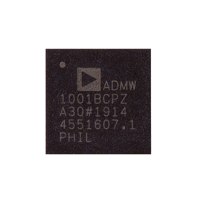
- Part No.:
- ADMW1001BCPZ
- Manufacturer:
- Analog Devices Inc.
- Category:
- Sensor and Detector Interfaces
- Package:
- 48-WFQFN Exposed Pad, CSP
- Datasheet:
-
 ADMW1001BCPZ.pdf
- Description:
- MEASUREWARE PRECISION CONDITION
- Quantity:
- Payment:

- Shipping:

Inventory:1,678
Please send an inquiry. Send us your inquiry, and we will respond immediately.
Product details
Overview
ADMW1001BCPZ from Analog Devices is a highly flexible, firmware-upgradeable condition monitoring IC that integrates sensor excitation, 24-bit Σ-Δ ADC conversion, embedded linearization (for PT100/1000 RTDs and J/K/T thermocouples), 50/60 Hz antialiasing rejection, and SPI/I²C sensor interfacing - enabling direct digitization of compensated temperature, bridge, and custom sensors in industrial asset health systems.
For engineers reviewing the ADMW1001BCPZ datasheet, ADMW1001BCPZ pinout, ADMW1001BCPZ application, or ADMW1001BCPZ equivalent, this page delivers verified technical context, real-world measurement channel configurations, confirmed diagnostic capabilities (open-wire, short-circuit, LUT validation), exact SPI master/slave timing parameters, and validated alternatives for condition monitoring node design.
Technical Context
The ADMW1001BCPZ implements dual independent 24-bit Σ-Δ ADCs with programmable gain (1–128), integrated PGA, on-chip FIFO, and per-channel sequencer logic - supporting simultaneous 50 Hz and 60 Hz notch filtering at 8.24 Hz output rate. It features two universal analog input channels (CH1/CH2) configurable for RTD, 4-/6-wire bridge, or ratiometric referencing, plus two dedicated thermocouple inputs (CH1_TC+/IEXC, CH2_TC+/IEXC) sharing COM_TC− and requiring TC_BIAS biasing.
Its digital architecture includes dual SPI interfaces (slave mode for host communication via CS0/MOSI0/MISO0/SCLK0; master mode for sensor control via CS1/MOSI1/MISO1/SCLK1), I²C sensor interface (SDA/SCL), GPIOs (GPIO0–GPIO2), and diagnostics engine with open-wire detection, short-circuit monitoring, and lookup table integrity checks - all managed by field-upgradable firmware within the MeasureWare ecosystem.
Key Specifications
| Parameter | Value and Actual Design Meaning |
|---|---|
| ADC Resolution | 24-bit no missing codes up to 250 Hz; enables high-precision temperature and strain measurements with <1 μV RMS noise at gain=8, 5 Hz. |
| Simultaneous 50/60 Hz Rejection | 97 dB rejection at fADC = 8.24 Hz, gain = 1 - eliminates mains interference without external filters in industrial environments. |
| Excitation Current Sources | Two programmable current sources (10 μA to 1 mA, ±5% initial tolerance); supports 2-/3-wire RTD excitation and cold-junction compensation. |
| Input Voltage Ranges | Differential ranges from ±125 mV (gain=8) to ±VREF (gain=1); buffered mode supports common-mode range AGND+0.1 V to AVDD−0.1 V. |
| Reference Accuracy | Internal 1.2 V reference with ±0.1% initial accuracy and ±5 ppm/°C tempco - ensures stable scaling across −40°C to +85°C operation. |
| Power Consumption | 6 mA active current, 15 μA hibernation current - enables battery-powered condition monitoring nodes with multi-day sleep cycles. |
| Digital Interfaces | SPI slave (CS0/MOSI0/MISO0/SCLK0), SPI master (CS1/MOSI1/MISO1/SCLK1), and dual I²C (SDA/SCL) - allows concurrent connection to host MCU and up to two I²C sensors (e.g., humidity, pressure). |
Pinout & Package
The ADMW1001BCPZ is housed in a 48-lead 7 mm × 7 mm LFCSP package with exposed thermal pad soldered to AGND. Pin functions are validated per Analog Devices Rev. 0 datasheet Figure 7 and Table 8.
| Pin/Terminal | Circuit Role | Design Meaning |
|---|---|---|
| CH1_AIN+, CH1_AIN− | Universal Channel 1 differential analog input | Accepts RTD, bridge, or voltage-output sensor signals; supports ratiometric referencing with internal excitation. |
| CH1_TC+/IEXC, CH2_TC+/IEXC, COM_TC− | Thermocouple input pair with shared return | Enables dual thermocouple measurement; requires TC_BIAS to bias COM_TC− to midscale for accurate cold-junction compensation. |
| CS0, MOSI0, MISO0, SCLK0 | SPI slave interface to host processor | Configurable frame-sync interface for reading measurement results, configuring channels, and managing FIFO status. |
| CS1, MOSI1, MISO1, SCLK1 | SPI master interface to external sensors | Drives clock and data to SPI-based sensors (e.g., digital pressure transducers); supports 8 MHz to 244 Hz clock speeds. |
| SDA, SCL | I²C sensor interface | Connects up to two I²C sensors (e.g., humidity, accelerometers); supports Fast Mode (400 kHz) and Standard Mode (100 kHz). |
| DRDY | Data Ready interrupt output | Programmable signal indicating completion of individual measurement, full cycle, or FIFO fill - reduces host polling overhead. |
Key Features
| Feature | Design Value |
|---|---|
| Embedded linearization for PT100/PT1000 RTDs | Automatic 2-/3-wire polynomial correction eliminates need for external lookup tables or host-side computation. |
| Per-measurement configuration | Independent gain, settling time, excitation current, and linearization settings per channel enable mixed-sensor nodes (e.g., RTD + thermocouple + bridge). |
| On-chip FIFO with sequencer | Holds multiple measurement results; sequencer automates cycling across configured channels - minimizes host CPU load in periodic monitoring applications. |
| Multiple embedded diagnostics | Real-time open-wire, short-circuit, and LUT validation detect sensor faults before measurement corruption occurs. |
| Firmware upgradeability | New sensor support (e.g., custom thermocouple types, I²C sensor drivers) deployed via flash loader - extends product lifetime without hardware change. |
Applications
| Industrial Asset Health Monitoring | Laboratory Instrumentation |
|---|---|
Use Scenario: Continuous vibration, temperature, and strain monitoring of rotating machinery (motors, pumps, gearboxes) in predictive maintenance systems. IC Role / Device Role / Timing Role: Primary measurement node digitizing PT1000 RTDs, Wheatstone bridge strain gauges, and K-type thermocouples with simultaneous 50/60 Hz rejection. Use Value: Enables single-chip acquisition of multi-sensor data with <1 μV RMS noise and automatic cold-junction compensation - reducing BOM count and calibration complexity. | Use Scenario: High-accuracy environmental chamber control requiring traceable temperature and humidity readings. IC Role / Device Role / Timing Role: Dual-role interface: measures calibrated RTD probes via CH1/CH2 universal channels while reading digital I²C humidity sensors via SDA/SCL. Use Value: Eliminates separate ADC and sensor interface ICs; embedded linearization and FIFO reduce host processing burden during multi-point calibration sweeps. |
| Smart Agriculture Sensor Nodes | Supply Chain Health Tracking |
Use Scenario: Battery-powered soil moisture, temperature, and ambient pressure logging in remote field deployments. IC Role / Device Role / Timing Role: Low-power measurement hub using hibernation mode (15 μA), wake-up trigger (WAKE_UP pin), and programmable sampling intervals (seconds to hours). Use Value: Achieves >1-year battery life via adaptive power management and on-chip diagnostics - prevents false alarms from disconnected or failed sensors. | Use Scenario: Tamper-evident cargo container monitors tracking temperature, shock, and door-open events during transit. IC Role / Device Role / Timing Role: Configurable measurement sequencer captures RTD temperature, I²C accelerometer shocks, and SPI pressure spikes - all timestamped and stored in FIFO. Use Value: Single-device synchronization of heterogeneous sensor data ensures correlated event analysis without external timing coordination. |
Equivalent & Alternatives
The following parts are listed as comparable options for similar condition monitoring applications.
| Alternative Part | Technical Difference | Application Difference | Selection Advice |
|---|---|---|---|
| AD7124-8BCPZ | 8-channel, 24-bit Σ-Δ ADC with PGA and internal reference; no built-in thermocouple linearization, no SPI master mode, no firmware-upgradeable sensor library. | Best for fixed-sensor-count systems where all channels are RTD/bridge only; lacks native thermocouple support and external sensor interface. | Select AD7124-8BCPZ when cost-sensitive, static sensor configurations dominate and field firmware updates are unnecessary. |
| MAX31865ACSM+ | Dedicated RTD-to-digital converter with 15-bit resolution, 4-wire support, and fault detection; no thermocouple or bridge capability, no I²C/SPI sensor interface, no FIFO or sequencer. | Optimized for high-accuracy 4-wire RTD-only applications (e.g., lab-grade thermometry); cannot replace ADMW1001BCPZ in multi-sensor nodes. | Choose MAX31865ACSM+ only for standalone, high-precision RTD measurement where thermocouple, bridge, or sensor expansion is not required. |
Compared with AD7124-8BCPZ and MAX31865ACSM+, the ADMW1001BCPZ uniquely combines firmware-upgradeable sensor support, dual SPI (master + slave), embedded thermocouple linearization, and on-chip sequencer/FIFO - making it the only option for scalable, future-proof condition monitoring nodes requiring mixed-sensor integration and field feature expansion.
Availability
ADMW1001BCPZ is available at Aetrix Electronics and suitable for industrial asset health monitoring, smart agriculture sensor nodes, and supply chain health tracking requiring stable component supply, long-term firmware maintainability, and field-upgradable measurement capabilities.
Supply support for ADMW1001BCPZ includes scheduled delivery planning, volume procurement assistance, BOM continuity management, traceable sourcing, and lifecycle availability coordination for OEM customers, industrial embedded developers, connected-device designers, and electronics production programs.
Manufacturer
Analog Devices, Inc. is a global leader in high-performance analog, mixed-signal, and digital signal processing semiconductors, serving industrial, automotive, communications, and healthcare markets.
The ADMW1001BCPZ belongs to Analog Devices' MeasureWare platform - a family of configurable, firmware-evolvable condition monitoring ICs designed specifically for rapid deployment of scalable, multi-sensor industrial IoT edge nodes.
FAQ
What sensor types does the ADMW1001BCPZ natively support without external firmware updates?
The ADMW1001BCPZ firmware revision 1.0 natively supports compensated J-, K-, and T-type thermocouples, 2-/3-wire PT100 and PT1000 RTDs, 4-wire Wheatstone bridges, and custom sensors via user-defined lookup tables. It also interfaces directly with I²C and SPI sensors through dedicated ports. All supported sensor types are handled with on-chip linearization and compensation - no host-side computation is required for basic operation of ADMW1001BCPZ.
How does the ADMW1001BCPZ achieve simultaneous 50 Hz and 60 Hz antialiasing rejection?
The ADMW1001BCPZ achieves simultaneous 50 Hz and 60 Hz antialiasing rejection through a digitally implemented notch filter synchronized to its Σ-Δ modulator clock. At an output data rate of 8.24 Hz, the device provides 97 dB rejection for both frequencies with gain = 1. This capability is hard-coded in the ADC's digital filter path and requires no external components - ensuring robust performance in electrically noisy industrial environments where ADMW1001BCPZ is deployed.
Can the ADMW1001BCPZ operate with an external reference, and what are the input requirements?
Yes, the ADMW1001BCPZ supports external reference inputs via VREF+ and VREF− pins. In buffered mode, the input range is AGND + 0.1 V to AVDD − 0.1 V; in unbuffered mode, the minimum differential voltage must be ≥400 mV. Input current is ≤27 nA (buffered) or ≤500 nA/V (unbuffered). External reference use maintains full 24-bit performance but requires careful layout to preserve noise immunity - a key consideration when designing precision measurement circuits with ADMW1001BCPZ.
What is the role of the TC_BIAS pin in thermocouple measurements with the ADMW1001BCPZ?
The TC_BIAS pin on the ADMW1001BCPZ provides a mid-supply bias voltage used to level-shift the COM_TC− pin during thermocouple measurements. Because thermocouple outputs are bipolar relative to AGND, TC_BIAS ensures the input stays within the ADC's common-mode range. It must be connected directly to COM_TC− when measuring thermocouples on CH1_TC+/IEXC or CH2_TC+/IEXC - failure to do so causes measurement saturation or clipping. This biasing scheme is mandatory for correct ADMW1001BCPZ thermocouple operation.
Does the ADMW1001BCPZ require pre-flashing with firmware before first use?
Yes, the ADMW1001BCPZ ships with only a firmware loader - not functional measurement firmware. To enable sensor support (RTD, thermocouple, bridge), users must flash the latest ADMW1001BCPZ firmware using Analog Devices' custom flash loader toolset. Firmware revisions are available on the ADMW1001 product page and MeasureWare Studio. Without flashing, the ADMW1001BCPZ remains non-operational - this step is essential before any measurement functionality can be accessed.
ADMW1001BCPZ Specifications
- Product attributes
- Attribute value
- Manufacturer:
- Analog Devices Inc.
- Package/Case:
- 48-WFQFN Exposed Pad, CSP
- Series:
- -
- Packaging:
- Bulk
- Product Status:
- Active
- Programmable:
- Not Verified
- Type:
- Sensor Interface - Unprogrammed
- Input Type:
- Logic
- Output Type:
- SPI
- Current - Supply:
- 6 mA
- Operating Temperature:
- -40°C ~ 85°C
- Grade:
- -
- Qualification:
- -
- Mounting Type:
- Surface Mount
- Supplier Device Package:
- 48-LFCSP (7x7)
ADMW1001BCPZ FAQ
1.How can I place an order for ADMW1001BCPZ through Aetrix?
Please submit a Request for Quotation (RFQ) for ADMW1001BCPZ on Aetrix. Our sales agent will provide a competitive quotation and guide you through the order confirmation once you accept the terms.
2.Are the price and stock information for ADMW1001BCPZ reliable?
The price and inventory of ADMW1001BCPZ are updated periodically and may fluctuate due to market conditions. Stock and pricing data are typically refreshed every 24 hours. Quotation validity for ADMW1001BCPZ is usually 5 days.
3.What payment methods are accepted for ADMW1001BCPZ?
We accept Wire Transfer, PayPal, Credit Card, Western Union, MoneyGram, and Escrow for ADMW1001BCPZ transactions.
Note: Certain payment methods may incur a processing fee.
4.How is shipping managed for ADMW1001BCPZ?
ADMW1001BCPZ orders can be shipped via leading logistics carriers, including DHL, UPS, FedEx, TNT, or Registered Mail.
Once your ADMW1001BCPZ order is processed, you will receive an email with the shipment details and tracking number.
Note: Tracking information may take up to 24 hours to appear. Express delivery typically takes 3–5 business days.
5.How can I obtain technical support or documentation for ADMW1001BCPZ?
For technical support, including ADMW1001BCPZ datasheets, pinout diagrams, or application guidance, please contact our engineering support team. They can provide detailed documentation and assistance for your ADMW1001BCPZ requirements.
6.How does Aetrix verify that ADMW1001BCPZ is sourced from the original manufacturer or authorized distributors?
All ADMW1001BCPZ products on Aetrix are procured from qualified distributors and authorized channels. Our dedicated quality assurance team conducts strict verification, including traceability checks and, if necessary, third-party testing. This ensures that ADMW1001BCPZ meets industry standards.
7.What is the process for return or replacement of ADMW1001BCPZ?
All ADMW1001BCPZ units undergo pre-shipment inspection (PSI). If there is an issue with ADMW1001BCPZ, returns or replacements are accepted under the following conditions:
1.Quantity discrepancies, incorrect items, or visible external defects (such as breakage or corrosion), acknowledged by Aetrix.
2.The issue is reported within 90 days of delivery.
3.The ADMW1001BCPZ part is unused and in its original packaging.
Return procedure for ADMW1001BCPZ:
1.Submit a request within 90 days.
2.Obtain a Return Material Authorization (RMA) from Aetrix.
ADMW1001BCPZ Tags

-
RE46C100S8TF
Microchip Technology

-
XTR111AIDRCR
Texas Instruments

-
XTR111AIDGQR
Texas Instruments

-
XTR117AIDGKR
Texas Instruments
-
XTR111AIDGQT
Texas Instruments

-
XTR115UA/2K5
Texas Instruments

-
MAX14626ETT+T
Analog Devices Inc./Maxim Integrated
-
XTR116UA/2K5
Texas Instruments
-
XTR115U/2K5
Texas Instruments
-
XTR116U/2K5
Texas Instruments

-
PGA308AIDGSR
Texas Instruments

-
XTR300AIRGWR
Texas Instruments
Tech Hub

A practical engineering guide to 3.3V and 5V logic compatibility, input thresholds, resistor dividers, translator ICs, MOSFET level shifting, I2C pull-ups, timing limits and power-sequencing risks.

The 74HC595 uses push-pull logic outputs, while the TPIC6B595 uses 50 V open-drain DMOS sinks for higher-power loads. This guide compares timing, current limits, 3.3 V interfacing, load wiring, thermal…

The 74HC595 converts serial data into eight stable parallel outputs. This guide covers pin functions, shift and storage timing, OE and MR behavior, drive-current limits, cascading, voltage compatibilit…

A technical comparison of level-sensitive latches and edge-triggered flip-flops, covering timing windows, setup and hold limits, master–slave operation, time borrowing, race-through, HDL inference and…

A D latch stores one bit while Enable controls when data can pass. This reference covers gate-level operation, truth tables, transparency, setup and hold timing, LE versus OE, common ICs and practical …

An SR latch stores one bit through cross-coupled feedback. This engineering reference covers NOR and NAND implementations, truth tables, forbidden-state recovery, gated operation, switch debouncing, fa…

Latch circuits retain one bit through feedback. This technical reference covers SR and D latches, truth tables, transparency, timing limits, latch-versus-flip-flop behavior, applications and common log…

An engineering guide to LED driver operation, constant-current and constant-voltage outputs, linear and switching topologies, dimming, IC selection, calculations, replacement compatibility, and fault c…

Operational amplifier guide covering op amp basics, feedback, ideal vs real op amps, common configurations, buffer circuits, offset, bias current, gain-bandwidth, slew rate, rail-to-rail limits and sel…

Jumper cables guide covering safe connection order, red and black clamp placement, final ground connection, cable gauge, length, clamp quality, copper vs CCA cables, jump starter comparison and battery…


