
 My Inquiry
 My Account


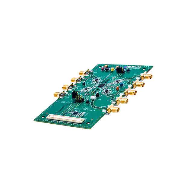
Analog Devices Inc. ADRF6520-EVALZ
- Part No.:
- ADRF6520-EVALZ
- Manufacturer:
- Analog Devices Inc.
- Category:
- RF, RFID, Wireless Evaluation Boards
- Package:
- Datasheet:
-
 ADRF6520-EVALZ.pdf
- Description:
- EVAL BOARD
- Quantity:
- Payment:

- Shipping:

Inventory:3,077
Please send an inquiry. Send us your inquiry, and we will respond immediately.
Product details
Overview
ADRF6520-EVALZ from Analog Devices is an evaluation board designed to characterize the ADRF6520 dual-channel, programmable low-pass filters and variable gain amplifiers (VGAs) for microwave radio applications with 2 GHz channel spacing. It supports single-ended and differential configurations, enables analog gain control (0 V to 1.5 V), provides SPI-programmable filter corner selection (up to 720 MHz), and includes on-chip RMS detectors with ~70 kHz video bandwidth.
For engineers reviewing the ADRF6520-EVALZ datasheet, ADRF6520-EVALZ setup procedure, ADRF6520-EVALZ software interface, or ADRF6520-EVALZ hardware modification options, this page delivers verified layout details, power-up sequence, test-point mapping, SDP-S controller integration, and configuration tradeoffs for filter mode vs. bypass mode operation.
Technical Context
The ADRF6520-EVALZ implements a complete signal chain interface for the ADRF6520 IC, featuring matched 50 Ω SMA input/output paths (INP1/INP2, OPP1/OPP2), analog gain control via blue/orange test points (VGN1/VGN2), and SPI access through P3 header (SDIO/SCLK/CS) or SDP-S controller via P5. It supports both default filter-bypass mode (>1 GHz bandwidth) and programmable low-pass filtering.
Hardware design includes balun-based single-ended-to-differential conversion capability (T1–T4), dc offset correction loop (500 Hz high-pass corner with C9/C16), RMS detector output routing (VRMS SMA or P2 header), and configurable network impedance matching using 0 Ω jumpers and resistor footprints (R1–R8, R9–R16, etc.).
Key Specifications
| Parameter | Value and Actual Design Meaning |
|---|---|
| Target Device | ADRF6520 dual-channel programmable low-pass filter and VGA IC |
| Supported Configurations | Single-ended (factory default) or user-modified differential I/O |
| Filter Corner Range | Programmable up to 720 MHz; bypass mode enables >1 GHz bandwidth |
| RMS Detector Video BW | ~70 kHz (set by 10 nF C7/C8); adjustable via capacitor replacement |
| Analog Gain Control Range | 0 V to 1.5 V per channel (VGN1/VGN2), controlling VGA1/VGA2 linear gain |
| Power Supply Requirement | 3.3 V @ 600 mA capable; draws ~395 mA (bypass) or ~425 mA (filter mode) |
| Interface Connectivity | SDP-S controller via 120-pin P5; SPI signals accessible at P3 header |
Availability
ADRF6520-EVALZ is available at Aetrix Electronics and suitable for microwave radio development, RF front-end validation, and high-speed ADC/demodulator interface testing requiring stable component supply and full-featured evaluation infrastructure.
Supply support for ADRF6520-EVALZ includes scheduled delivery planning, volume procurement assistance, BOM continuity management, traceable sourcing, and lifecycle availability coordination for OEM customers, industrial embedded developers, connected-device designers, and electronics production programs.
Manufacturer
Analog Devices, Inc. is a global leader in high-performance analog, mixed-signal, and digital signal processing semiconductors, headquartered in Norwood, MA.
The ADRF6520-EVALZ belongs to Analog Devices' RF & Microwave evaluation platform family, engineered specifically to accelerate characterization and system integration of programmable RF signal conditioning ICs in wireless infrastructure and point-to-point radio applications.
FAQ
What is the primary function of the ADRF6520-EVALZ?
The ADRF6520-EVALZ is a dedicated evaluation board for the ADRF6520 dual-channel programmable low-pass filter and VGA IC. It enables engineers to validate filter response, analog gain control behavior, RMS detection accuracy, dc offset correction performance, and SPI register configuration - all under real-world test conditions using standard lab equipment like signal generators and spectrum analyzers. The ADRF6520-EVALZ itself contains no active silicon beyond the ADRF6520-ACPZ and supporting passive components.
How do I configure the ADRF6520-EVALZ for differential operation?
To configure the ADRF6520-EVALZ for differential I/O, depopulate baluns T1/T3 (for Channel 1 input/output) and install 0 Ω resistors at designated pads (T1_1/T1_3/T1_4/T1_5 and T3_1/T3_3/T3_4/T3_5), while populating R42/R44. Similar modifications apply to Channel 2 using T2/T4. The board's silkscreen and UG-1045 schematics identify exact pad locations. Differential mode requires external baluns or transformer-coupled sources/sinks and alters common-mode voltage handling.
What power supply requirements does the ADRF6520-EVALZ have?
The ADRF6520-EVALZ requires a single 3.3 V supply capable of delivering ≥600 mA, applied between the red VPS test point and any green COM1/COM2/COM3 ground point. Default power-up current draw is ~395 mA in filter-bypass mode and increases to ~425 mA when filters are enabled. Separate 0 V supplies (≤1 mA limit) must be applied to VGN1 and VGN2 test points for gain control initialization.
Can I use the ADRF6520-EVALZ without the SDP-S controller board?
Yes - the ADRF6520-EVALZ provides direct SPI access via the P3 3×2 pin header (SDIO, SCLK, CS on pins 1/3/5; all grounded on pins 2/4/6), enabling custom microcontroller-based programming. However, the official ADRF6520 Evaluation Software and GUI require the SDP-S controller board connected via the 120-pin P5 interface. Standalone SPI use demands manual register writes per the ADRF6520 data sheet.
What is the role of the VRMS connector on the ADRF6520-EVALZ?
The VRMS SMA connector provides direct access to the output of the ADRF6520's integrated RMS detectors, allowing measurement of signal envelope magnitude. It can also be accessed via the 2-pin P2 header for low-parasitic FET probe connections. The detector's video bandwidth (~70 kHz) is set by C7/C8 (10 nF); changing these capacitors adjusts response time and bandwidth - critical for AGC loop stability in modulated signal applications.
ADRF6520-EVALZ Specifications
- Product attributes
- Attribute value
- Manufacturer:
- Analog Devices Inc.
- Series:
- -
- Packaging:
- Bulk
- Product Status:
- Active
- Type:
- Filter
- Frequency:
- 36MHz ~ 720MHz
- Contents:
- Board(s)
- Utilized IC / Part:
- ADRF6520
ADRF6520-EVALZ FAQ
1.How can I place an order for ADRF6520-EVALZ through Aetrix?
Please submit a Request for Quotation (RFQ) for ADRF6520-EVALZ on Aetrix. Our sales agent will provide a competitive quotation and guide you through the order confirmation once you accept the terms.
2.Are the price and stock information for ADRF6520-EVALZ reliable?
The price and inventory of ADRF6520-EVALZ are updated periodically and may fluctuate due to market conditions. Stock and pricing data are typically refreshed every 24 hours. Quotation validity for ADRF6520-EVALZ is usually 5 days.
3.What payment methods are accepted for ADRF6520-EVALZ?
We accept Wire Transfer, PayPal, Credit Card, Western Union, MoneyGram, and Escrow for ADRF6520-EVALZ transactions.
Note: Certain payment methods may incur a processing fee.
4.How is shipping managed for ADRF6520-EVALZ?
ADRF6520-EVALZ orders can be shipped via leading logistics carriers, including DHL, UPS, FedEx, TNT, or Registered Mail.
Once your ADRF6520-EVALZ order is processed, you will receive an email with the shipment details and tracking number.
Note: Tracking information may take up to 24 hours to appear. Express delivery typically takes 3–5 business days.
5.How can I obtain technical support or documentation for ADRF6520-EVALZ?
For technical support, including ADRF6520-EVALZ datasheets, pinout diagrams, or application guidance, please contact our engineering support team. They can provide detailed documentation and assistance for your ADRF6520-EVALZ requirements.
6.How does Aetrix verify that ADRF6520-EVALZ is sourced from the original manufacturer or authorized distributors?
All ADRF6520-EVALZ products on Aetrix are procured from qualified distributors and authorized channels. Our dedicated quality assurance team conducts strict verification, including traceability checks and, if necessary, third-party testing. This ensures that ADRF6520-EVALZ meets industry standards.
7.What is the process for return or replacement of ADRF6520-EVALZ?
All ADRF6520-EVALZ units undergo pre-shipment inspection (PSI). If there is an issue with ADRF6520-EVALZ, returns or replacements are accepted under the following conditions:
1.Quantity discrepancies, incorrect items, or visible external defects (such as breakage or corrosion), acknowledged by Aetrix.
2.The issue is reported within 90 days of delivery.
3.The ADRF6520-EVALZ part is unused and in its original packaging.
Return procedure for ADRF6520-EVALZ:
1.Submit a request within 90 days.
2.Obtain a Return Material Authorization (RMA) from Aetrix.
ADRF6520-EVALZ Tags
-
113991054
Seeed Technology Co., Ltd
-
SC0918
Raspberry Pi

-
113991114
Seeed Technology Co., Ltd
-
ESP32-C6-DEVKITM-1-N4
Espressif Systems
-
ESP32-DEVKITM-1
Espressif Systems
-
C008
M5Stack Technology Co., Ltd.
-
ESP32-C3-DEVKITC-02
Espressif Systems
-
ESP32-C6-DEVKITC-1-N8
Espressif Systems
-
DFR0478
DFRobot
-
102010448
Seeed Technology Co., Ltd
-
ESP32-DEVKITC-32E
Espressif Systems
-
ESP32-DEVKITC-32UE
Espressif Systems
Tech Hub

A practical engineering guide to 3.3V and 5V logic compatibility, input thresholds, resistor dividers, translator ICs, MOSFET level shifting, I2C pull-ups, timing limits and power-sequencing risks.

The 74HC595 uses push-pull logic outputs, while the TPIC6B595 uses 50 V open-drain DMOS sinks for higher-power loads. This guide compares timing, current limits, 3.3 V interfacing, load wiring, thermal…

The 74HC595 converts serial data into eight stable parallel outputs. This guide covers pin functions, shift and storage timing, OE and MR behavior, drive-current limits, cascading, voltage compatibilit…

A technical comparison of level-sensitive latches and edge-triggered flip-flops, covering timing windows, setup and hold limits, master–slave operation, time borrowing, race-through, HDL inference and…

A D latch stores one bit while Enable controls when data can pass. This reference covers gate-level operation, truth tables, transparency, setup and hold timing, LE versus OE, common ICs and practical …

An SR latch stores one bit through cross-coupled feedback. This engineering reference covers NOR and NAND implementations, truth tables, forbidden-state recovery, gated operation, switch debouncing, fa…

Latch circuits retain one bit through feedback. This technical reference covers SR and D latches, truth tables, transparency, timing limits, latch-versus-flip-flop behavior, applications and common log…

An engineering guide to LED driver operation, constant-current and constant-voltage outputs, linear and switching topologies, dimming, IC selection, calculations, replacement compatibility, and fault c…

Operational amplifier guide covering op amp basics, feedback, ideal vs real op amps, common configurations, buffer circuits, offset, bias current, gain-bandwidth, slew rate, rail-to-rail limits and sel…

Jumper cables guide covering safe connection order, red and black clamp placement, final ground connection, cable gauge, length, clamp quality, copper vs CCA cables, jump starter comparison and battery…


