
 My Inquiry
 My Account


Texas Instruments ADS54RF63_ADX4
- Part No.:
- ADS54RF63_ADX4
- Manufacturer:
- Texas Instruments
- Package:
- Datasheet:
-
 ADS54RF63_ADX4.pdf
- Description:
- EVAL MODULE FOR ADS54RF63
- Quantity:
- Payment:

- Shipping:

Inventory:2,933
Please send an inquiry. Send us your inquiry, and we will respond immediately.
Product details
Overview
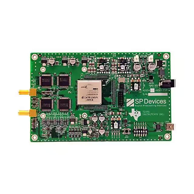
ADS54RF63_ADX4 from Texas Instruments is a single-channel, 12-bit, 2.2 GSPS evaluation module (EVM) built around four time-interleaved ADS54RF63 analog-to-digital converters. It features an external 550 MHz clock interface with phase-shifted sampling (0°/90°/180°/270°), LVDS source-synchronous data output to an FPGA, and USB 2.0–compatible RS-232-over-USB interface delivering up to 3 Mbit/s data throughput. It is used for high-speed RF signal acquisition in radar, wideband communications, and instrumentation prototyping.
For engineers reviewing the ADS54RF63_ADX4 datasheet, ADS54RF63_ADX4 pinout, ADS54RF63_ADX4 application, or ADS54RF63_ADX4 equivalent, this EVM provides validated hardware design, ADCapture Lab software with FFT-based analysis (SFDR, SNDR, ENOB), MATLAB integration, and full schematic/layout documentation - enabling rapid characterization of ultra-high-speed ADC performance without custom board development.
Technical Context
The ADS54RF63_ADX4 implements time-interleaved sampling using four ADS54RF63 ADCs driven by phase-shifted 550 MHz clocks derived from a single external source. An onboard Virtex-5 FPGA (XC5VSX50T) manages clock distribution via PLL, captures interleaved LVDS data, and handles USB protocol translation through an FT232RQ bridge.
Signal chain includes precision clock conditioning (ADCLK925B fanout buffers), analog input conditioning with BB184 varactor-tuned front-end, and power delivery via multiple TI DC/DC modules (PTH08080W, PTH08T231W) and LDOs (REG104GA-3.3G4, TPS72301). Performance validation supports single-tone and two-tone FFT analysis with Nyquist zone selection and windowing (Blackman-Harris, Hamming).
Key Specifications
| Parameter | Value and Actual Design Meaning |
|---|---|
| ADC Resolution | 12-bit - defines quantization step size and dynamic range for RF input signals up to Nyquist frequency (1.1 GHz). |
| Effective Sampling Rate | 2.2 GSPS - achieved via four 550 MSPS ADS54RF63 ADCs operating in time-interleaved mode. |
| Data Interface | LVDS source-synchronous - enables deterministic timing alignment between sampled data and clock edge for FPGA capture. |
| Host Interface | USB 2.0 (via FT232RQ) at 3 Mbit/s - provides plug-and-play connectivity to Windows PCs without requiring PCIe or dedicated digitizer hardware. |
| Analysis Software | ADCapture Lab with FFT, SFDR, SNDR, ENOB, and code histogram - delivers production-grade ADC performance metrics directly from captured data batches. |
| FPGA Resource | Xilinx Virtex-5 XC5VSX50T-3FFG665C - provides sufficient logic and memory for real-time interleaving control, buffering, and USB protocol handling. |
Availability
ADS54RF63_ADX4 is available at Aetrix Electronics and suitable for radar waveform digitization, wideband spectrum monitoring, high-frequency test equipment development, and academic RF research requiring stable component supply and full evaluation support.
Supply support for ADS54RF63_ADX4 includes scheduled delivery planning, volume procurement assistance, BOM continuity management, traceable sourcing, and lifecycle availability coordination for OEM customers, industrial embedded developers, connected-device designers, and electronics production programs.
Manufacturer
Texas Instruments is a global semiconductor company headquartered in Dallas, Texas, specializing in analog, embedded processing, and high-speed data conversion technologies for industrial, automotive, and communications markets.
The ADS54RF63_ADX4 belongs to TI's high-speed data converter evaluation platform family, designed specifically to accelerate prototyping and validation of RF-sampling ADCs in demanding applications such as electronic warfare, 5G mmWave test, and scientific instrumentation.
FAQ
What is the primary function of the ADS54RF63_ADX4?
The ADS54RF63_ADX4 is a complete evaluation module for the ADS54RF63 ultra-high-speed ADC. It integrates four time-interleaved ADS54RF63 devices, clock distribution circuitry, FPGA-based data capture, and USB interface to enable immediate RF signal acquisition and analysis - eliminating the need for custom PCB design when evaluating 12-bit, 2.2 GSPS ADC performance.
Does the ADS54RF63_ADX4 require external clock sources?
Yes, the ADS54RF63_ADX4 requires an external 550 MHz clock applied to its SMA input. The onboard FPGA generates four phase-shifted clock signals (0°, 90°, 180°, 270°) to drive the four ADS54RF63 ADCs. No internal oscillator or clock synthesis is provided - precise external clocking is mandatory for proper interleaved operation of the ADS54RF63_ADX4.
Which software tools are supported for the ADS54RF63_ADX4?
The ADS54RF63_ADX4 supports ADCapture Lab (Windows-only standalone GUI) and MATLAB via the instrusb() interface. ADCapture Lab provides real-time plotting, FFT analysis, SFDR/SNDR/ENOB calculation, and data export in ASCII, binary, or text formats. MATLAB integration allows scripted acquisition and custom algorithm development using raw ADC samples from the ADS54RF63_ADX4.
What FPGA is used on the ADS54RF63_ADX4 board?
The ADS54RF63_ADX4 uses the Xilinx Virtex-5 XC5VSX50T-3FFG665C FPGA. This device handles clock distribution via internal PLL, LVDS data capture from all four ADS54RF63 ADCs, interleaving alignment, buffering, and USB protocol translation through the FT232RQ bridge - forming the core digital signal path of the ADS54RF63_ADX4.
Is the ADS54RF63_ADX4 RoHS compliant and production-ready?
The ADS54RF63_ADX4 is RoHS compliant (as confirmed in its Bill of Materials), but it is explicitly designated for engineering development, demonstration, and evaluation only - not for end-product deployment. TI states it lacks full EMC, safety, and environmental certifications required for commercial products. Its purpose is rapid ADC characterization, not drop-in system integration.
ADS54RF63_ADX4 Specifications
- Product attributes
- Attribute value
- Manufacturer:
- Texas Instruments
- Series:
- -
- Packaging:
- Box
- Product Status:
- Obsolete
- Number of A/D Converters:
- 4
- Number of Bits:
- 12
- Sampling Rate (Per Second):
- 550M
- Data Interface:
- LVDS
- Input Range:
- 2.2Vpp
- Power (Typ) @ Conditions:
- -
- Utilized IC / Part:
- ADS54RF63
- Contents:
- Board(s)
ADS54RF63_ADX4 FAQ
1.How can I place an order for ADS54RF63_ADX4 through Aetrix?
Please submit a Request for Quotation (RFQ) for ADS54RF63_ADX4 on Aetrix. Our sales agent will provide a competitive quotation and guide you through the order confirmation once you accept the terms.
2.Are the price and stock information for ADS54RF63_ADX4 reliable?
The price and inventory of ADS54RF63_ADX4 are updated periodically and may fluctuate due to market conditions. Stock and pricing data are typically refreshed every 24 hours. Quotation validity for ADS54RF63_ADX4 is usually 5 days.
3.What payment methods are accepted for ADS54RF63_ADX4?
We accept Wire Transfer, PayPal, Credit Card, Western Union, MoneyGram, and Escrow for ADS54RF63_ADX4 transactions.
Note: Certain payment methods may incur a processing fee.
4.How is shipping managed for ADS54RF63_ADX4?
ADS54RF63_ADX4 orders can be shipped via leading logistics carriers, including DHL, UPS, FedEx, TNT, or Registered Mail.
Once your ADS54RF63_ADX4 order is processed, you will receive an email with the shipment details and tracking number.
Note: Tracking information may take up to 24 hours to appear. Express delivery typically takes 3–5 business days.
5.How can I obtain technical support or documentation for ADS54RF63_ADX4?
For technical support, including ADS54RF63_ADX4 datasheets, pinout diagrams, or application guidance, please contact our engineering support team. They can provide detailed documentation and assistance for your ADS54RF63_ADX4 requirements.
6.How does Aetrix verify that ADS54RF63_ADX4 is sourced from the original manufacturer or authorized distributors?
All ADS54RF63_ADX4 products on Aetrix are procured from qualified distributors and authorized channels. Our dedicated quality assurance team conducts strict verification, including traceability checks and, if necessary, third-party testing. This ensures that ADS54RF63_ADX4 meets industry standards.
7.What is the process for return or replacement of ADS54RF63_ADX4?
All ADS54RF63_ADX4 units undergo pre-shipment inspection (PSI). If there is an issue with ADS54RF63_ADX4, returns or replacements are accepted under the following conditions:
1.Quantity discrepancies, incorrect items, or visible external defects (such as breakage or corrosion), acknowledged by Aetrix.
2.The issue is reported within 90 days of delivery.
3.The ADS54RF63_ADX4 part is unused and in its original packaging.
Return procedure for ADS54RF63_ADX4:
1.Submit a request within 90 days.
2.Obtain a Return Material Authorization (RMA) from Aetrix.
ADS54RF63_ADX4 Tags
-
1083
Adafruit Industries LLC
-
1085
Adafruit Industries LLC
-
ADS7038Q1EVM-PDK
Texas Instruments
-
ADS8688EVM-PDK
Texas Instruments
-
EVAL-AD7606C18FMCZ
Analog Devices Inc.
-
ADS1232REF
Texas Instruments
-
EVAL-AD4134FMCZ
Analog Devices Inc.
-
EVAL-AD7768FMCZ
Analog Devices Inc.
-
ADC128S102EVM
Texas Instruments
-
ADS124S08EVM
Texas Instruments
-
ADC6140EVM-PDK
Texas Instruments
-
ADS7066EVM-PDK
Texas Instruments
Tech Hub

A practical engineering guide to 3.3V and 5V logic compatibility, input thresholds, resistor dividers, translator ICs, MOSFET level shifting, I2C pull-ups, timing limits and power-sequencing risks.

The 74HC595 uses push-pull logic outputs, while the TPIC6B595 uses 50 V open-drain DMOS sinks for higher-power loads. This guide compares timing, current limits, 3.3 V interfacing, load wiring, thermal…

The 74HC595 converts serial data into eight stable parallel outputs. This guide covers pin functions, shift and storage timing, OE and MR behavior, drive-current limits, cascading, voltage compatibilit…

A technical comparison of level-sensitive latches and edge-triggered flip-flops, covering timing windows, setup and hold limits, master–slave operation, time borrowing, race-through, HDL inference and…

A D latch stores one bit while Enable controls when data can pass. This reference covers gate-level operation, truth tables, transparency, setup and hold timing, LE versus OE, common ICs and practical …

An SR latch stores one bit through cross-coupled feedback. This engineering reference covers NOR and NAND implementations, truth tables, forbidden-state recovery, gated operation, switch debouncing, fa…

Latch circuits retain one bit through feedback. This technical reference covers SR and D latches, truth tables, transparency, timing limits, latch-versus-flip-flop behavior, applications and common log…

An engineering guide to LED driver operation, constant-current and constant-voltage outputs, linear and switching topologies, dimming, IC selection, calculations, replacement compatibility, and fault c…

Operational amplifier guide covering op amp basics, feedback, ideal vs real op amps, common configurations, buffer circuits, offset, bias current, gain-bandwidth, slew rate, rail-to-rail limits and sel…

Jumper cables guide covering safe connection order, red and black clamp placement, final ground connection, cable gauge, length, clamp quality, copper vs CCA cables, jump starter comparison and battery…


