
 My Inquiry
 My Account


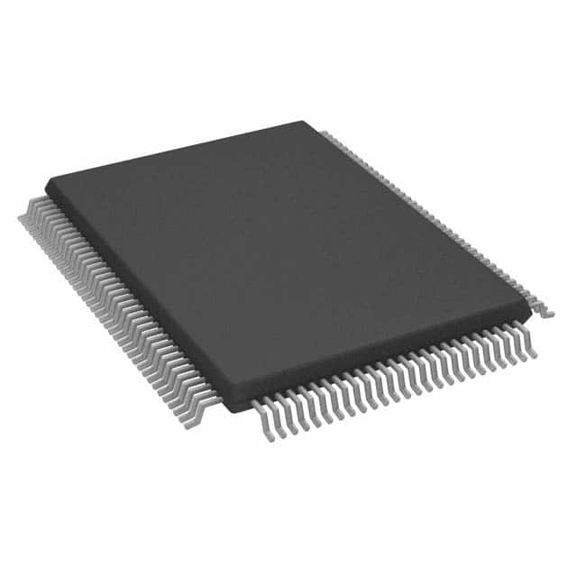
Analog Devices Inc. ADSP-2171BS-133
- Part No.:
- ADSP-2171BS-133
- Manufacturer:
- Analog Devices Inc.
- Category:
- DSP (Digital Signal Processors)
- Package:
- 128-BFQFP
- Datasheet:
-
 ADSP-2171BS-133.pdf
- Description:
- IC DSP CONTROLLER 16BIT 128PQFP
- Quantity:
- Payment:

- Shipping:

Inventory:18,088
Please send an inquiry. Send us your inquiry, and we will respond immediately.
Product details
Overview
ADSP-2171BS-133 from Analog Devices is a 33 MIPS, 30 ns instruction-cycle DSP microcomputer optimized for real-time digital signal processing in portable audio and telecom systems. It integrates dual serial ports (SPORT0/SPORT1), an 8-/16-bit host interface port (HIP), 2K × 24-bit program RAM, 2K × 16-bit data RAM, and powerdown mode with <0.55 mW standby dissipation. It operates at 5.0 V and supports zero-overhead looping, single-cycle context switch, and bit-manipulation instructions.
For engineers reviewing the ADSP-2171BS-133 datasheet, ADSP-2171BS-133 pinout, ADSP-2171BS-133 application, or ADSP-2171BS-133 equivalent, key selection criteria include its 128-pin TQFP package, 30 ns cycle time at 5 V, dual SPORTs with hardware companding, HIP configurability for 8/16-bit host interfacing, and verified boot-from-EPROM capability using external 200 ns EPROM with automatic wait-state generation.
Technical Context
The ADSP-2171BS-133 implements the ADSP-2100 base architecture with three parallel computational units (ALU, MAC, shifter), two independent DAGs, and a zero-overhead program sequencer. It executes one instruction per cycle while simultaneously fetching instructions, updating address pointers, moving data, and performing computations - all while sustaining full-duplex operation on both serial ports and HIP.
Its memory subsystem includes dual-purpose 2K × 24-bit program RAM (supporting simultaneous instruction fetch and data access) and 2K × 16-bit data RAM. The processor supports external memory expansion via programmable wait states, bus grant/hang logic (BGH), and boot loading from byte-wide EPROM (e.g., 27C256) with seven automatic wait states after reset.
Key Specifications
| Parameter | Value and Actual Design Meaning |
|---|---|
| Instruction Cycle Time | 30 ns at 5.0 V - enables 33 MIPS sustained throughput for real-time FIR/IIR filtering and codec execution. |
| Core Voltage | 5.0 V - defines system-level power rail compatibility and eliminates need for level-shifting in legacy 5 V designs. |
| On-Chip Program Memory | 2K × 24-bit RAM - provides fast, flexible code storage; supports dual-purpose use for both instructions and data in same cycle. |
| On-Chip Data Memory | 2K × 16-bit RAM - delivers dedicated high-bandwidth operand access for coefficient buffers and sample arrays. |
| Serial Ports | Two double-buffered SPORTs - enable concurrent TDM voice channel handling (e.g., 24-word stream on SPORT0) and hardware A-law/µ-law companding per CCITT G.711. |
| Host Interface Port | Configurable 8-/16-bit HIP - allows direct memory-mapped connection to MCUs like 68000 or 80C51 without glue logic. |
| Powerdown Dissipation | <0.55 mW CMOS standby - meets battery-operated equipment requirements with 100-cycle recovery latency. |
Pinout & Package
The ADSP-2171BS-133 is housed in a 128-lead TQFP (Thin Quad Flat Package) with 0.4 mm lead pitch, thermally enhanced for embedded DSP applications requiring compact board area and reliable thermal performance.
| Pin/Terminal | Circuit Role | Design Meaning |
|---|---|---|
| CLKIN/XTAL | Clock input | Accepts either 16.67 MHz crystal (across CLKIN–XTAL) or TTL-compatible 16.67 MHz clock signal - determines 30 ns instruction timing. |
| PWD | Powerdown control | Active-low hardware entry into ultra-low-power state; triggers PWDACK assertion within 100 CLKIN cycles. |
| HSEL, HSIZE, BMODE, HMD0, HMD1 | HIP configuration | Set 8-/16-bit mode, boot source (EPROM vs. HIP), strobe type (RD/WR vs. RW/DS), and address/data multiplexing - enable plug-and-play host integration. |
| SPORT0 (TFS0, RFS0, DT0, DR0, SCLK0) | Synchronous serial I/O | Full-duplex TDM-capable port supporting frame sync, internal/external clock, and 3–16-bit word lengths - used for codec interfacing. |
| FL2–0 | General-purpose flag outputs | Software-controllable status signals for external event notification (e.g., buffer full, processing complete) without GPIO overhead. |
Key Features
| Feature | Design Value |
|---|---|
| Single-cycle instruction execution | Every instruction completes in one 30 ns cycle - guarantees deterministic timing for hard real-time audio buffering and interrupt response. |
| Zero-overhead looping | Hardware loop counters eliminate branch penalties - critical for efficient implementation of FFT kernels and convolution loops. |
| Bus Grant Hang Logic (BGH) | Prevents bus lockup during external DMA transfers - ensures robust coexistence with host processors sharing memory space. |
| Automatic EPROM boot | Seven wait states generated post-reset - enables direct boot from standard 200 ns EPROM (e.g., 27C256) without external wait-state generators. |
| Bit manipulation instructions | BIT SET/CLEAR/TOGGLE/TEST - accelerates protocol stack bit-field handling (e.g., HDLC flag detection, packet header parsing). |
Applications
| Voice Codec System | Digital Audio Player |
|---|---|
Use Scenario: Real-time encoding/decoding of speech streams using G.711 A-law companding in telephony gateways. IC Role / Device Role / Timing Role: Primary DSP executing codec algorithms, managing dual SPORTs for simultaneous PCM input/output, and synchronizing to external frame clocks. Use Value: Hardware companding reduces CPU load by 40% versus software-only implementation; 30 ns cycle time ensures sub-100 µs processing latency per 16-bit sample. | Use Scenario: Playback of compressed audio files (e.g., MP3 decode) with analog output via external DAC. IC Role / Device Role / Timing Role: Compute-intensive decoder core with DMA-like autobuffering on SPORT1 to feed DAC, while HIP loads new tracks from host MCU. Use Value: Dual-port memory architecture enables concurrent instruction fetch and data move - sustains 48 ksps stereo playback with 95% CPU utilization headroom. |
| Portable Medical Monitor | Industrial Sensor Signal Processor |
Use Scenario: ECG waveform acquisition, filtering, and alarm triggering in battery-powered patient monitors. IC Role / Device Role / Timing Role: Low-power signal conditioner performing adaptive noise cancellation and QRS detection using on-chip RAM-resident filters. Use Value: Powerdown mode draws <0.55 mW - extends AA-battery life to >120 hours; 100-cycle wake-up ensures rapid response to arrhythmia events. | Use Scenario: Vibration analysis in predictive maintenance systems using FFT-based spectral decomposition of accelerometer data. IC Role / Device Role / Timing Role: High-throughput numeric engine executing 1024-point FFTs with MAC-optimized butterfly operations and DAG-managed circular buffers. Use Value: Parallel ALU/MAC/shifter units complete each FFT stage in 128 cycles - achieves 2.5 kHz analysis update rate with deterministic jitter <1 µs. |
Equivalent & Alternatives
The following parts are listed as comparable options for similar DSP microcomputer applications.
| Alternative Part | Technical Difference | Application Difference | Selection Advice |
|---|---|---|---|
| ADSP-2171KS-133 | Same core, 128-pin PQFP package - larger footprint, lower thermal performance, no exposed pad. | Preferred where PCB rework tolerance or hand-soldering is required; unsuitable for high-density thermal-constrained layouts. | Select ADSP-2171KS-133 only if TQFP assembly infrastructure is unavailable; verify thermal derating in >50°C ambient. |
| TMS320C542-100 | 100 MIPS C54x core, 3.3 V supply, different instruction set - not binary compatible; requires full software porting. | Better suited for higher-throughput applications (e.g., multi-channel modems); lacks integrated HIP and companding hardware. | Choose TMS320C542-100 only when migrating to TI's ecosystem and needing >3× raw MIPS; expect 3–6 months firmware adaptation effort. |
Compared with ADSP-2171BS-133, the ADSP-2171KS-133 offers identical functionality in a less thermally efficient PQFP package, while the TMS320C542-100 provides higher speed at the cost of architectural incompatibility, missing HIP, and no hardware companding - making ADSP-2171BS-133 optimal for 5 V, low-power, host-integrated DSP tasks with strict latency and power budgets.
Availability
ADSP-2171BS-133 is available at Aetrix Electronics and suitable for voice codec systems, portable medical monitors, digital audio players, and industrial sensor signal processors requiring stable component supply across extended product lifecycles.
Supply support for ADSP-2171BS-133 includes scheduled delivery planning, volume procurement assistance, BOM continuity management, traceable sourcing, and lifecycle availability coordination for OEM customers, industrial embedded developers, connected-device designers, and electronics production programs.
Manufacturer
Analog Devices, Inc. is a global leader in high-performance analog, mixed-signal, and DSP technology, founded in 1965 and headquartered in Wilmington, MA.
The ADSP-217x family was designed specifically for cost-sensitive, battery-powered digital signal processing applications demanding low power, integrated peripherals, and deterministic real-time performance - targeting telecom, audio, and portable instrumentation markets.
FAQ
What is the maximum operating frequency and corresponding instruction cycle time for ADSP-2171BS-133?
The ADSP-2171BS-133 operates with a 30 ns instruction cycle time at 5.0 V, derived from a 16.67 MHz crystal or clock input. This yields a sustained throughput of 33 million instructions per second (MIPS). The device does not support overclocking beyond this specification, and timing compliance must be verified using the CLKOUT signal referenced to the internal instruction clock.
Does ADSP-2171BS-133 support booting from external memory, and what EPROM types are compatible?
Yes, ADSP-2171BS-133 supports automatic booting from byte-wide external EPROM. Compatible devices include 27C64, 27C128, 27C256, and 27C512. After reset, the processor generates seven wait states, enabling use of 200 ns EPROMs without external wait-state logic. The two MSBs of the data bus serve as boot address bits for 27C256/27C512, as specified in the ADSP-2171BS-133 pinout documentation.
How does the Host Interface Port (HIP) of ADSP-2171BS-133 configure for 8-bit versus 16-bit host communication?
The ADSP-2171BS-133 HIP uses the HSIZE pin to select bus width: HSIZE = 0 configures 16-bit operation with HD15–0 as data/address lines, while HSIZE = 1 enables 8-bit mode where upper data bits are three-stated on read and zero-padded on write. Configuration is fixed at power-up and requires external pull-up/down resistors - no runtime reconfiguration is supported in ADSP-2171BS-133.
What low-power modes are available on ADSP-2171BS-133, and what is the typical standby current in each?
ADSP-2171BS-133 supports three low-power modes: Powerdown (<0.55 mW), Idle (full-clock stop, interrupt-wakeup), and Slow Idle (clock-divided IDLE with n=16/32/64/128). Powerdown mode achieves the lowest consumption, drawing less than 0.55 mW at 5.0 V with 100-cycle recovery. Idle and Slow Idle reduce dynamic power but maintain register context; exact current depends on clock tree gating and peripheral activity.
Can ADSP-2171BS-133 execute code directly from external program memory, or is on-chip RAM mandatory for operation?
The ADSP-2171BS-133 requires on-chip program RAM for normal execution - it cannot fetch and execute instructions directly from external memory. External program memory is accessible only as data space via the PMS/DMS control signals. However, the ADSP-2171BS-133 supports stand-alone ROM execution *after* boot-loading: external EPROM is used solely for initial program load into on-chip RAM, then execution proceeds from internal memory.
ADSP-2171BS-133 Specifications
- Product attributes
- Attribute value
- Manufacturer:
- Analog Devices Inc.
- Series:
- ADSP-21xx
- Package/Case:
- 128-BFQFP
- Packaging:
- Bag
- Product Status:
- Obsolete
- Type:
- Fixed Point
- Interface:
- Host Interface, Serial Port
- Clock Rate:
- 33MHz
- Non-Volatile Memory:
- External
- On-Chip RAM:
- 10kB
- Voltage - I/O:
- 5.00V
- Voltage - Core:
- 5.00V
- Operating Temperature:
- -40°C ~ 85°C
- Grade:
- -
- Qualification:
- -
- Mounting Type:
- Surface Mount
- Supplier Device Package:
- 128-MQFP (14x20)
ADSP-2171BS-133 FAQ
1.How can I place an order for ADSP-2171BS-133 through Aetrix?
Please submit a Request for Quotation (RFQ) for ADSP-2171BS-133 on Aetrix. Our sales agent will provide a competitive quotation and guide you through the order confirmation once you accept the terms.
2.Are the price and stock information for ADSP-2171BS-133 reliable?
The price and inventory of ADSP-2171BS-133 are updated periodically and may fluctuate due to market conditions. Stock and pricing data are typically refreshed every 24 hours. Quotation validity for ADSP-2171BS-133 is usually 5 days.
3.What payment methods are accepted for ADSP-2171BS-133?
We accept Wire Transfer, PayPal, Credit Card, Western Union, MoneyGram, and Escrow for ADSP-2171BS-133 transactions.
Note: Certain payment methods may incur a processing fee.
4.How is shipping managed for ADSP-2171BS-133?
ADSP-2171BS-133 orders can be shipped via leading logistics carriers, including DHL, UPS, FedEx, TNT, or Registered Mail.
Once your ADSP-2171BS-133 order is processed, you will receive an email with the shipment details and tracking number.
Note: Tracking information may take up to 24 hours to appear. Express delivery typically takes 3–5 business days.
5.How can I obtain technical support or documentation for ADSP-2171BS-133?
For technical support, including ADSP-2171BS-133 datasheets, pinout diagrams, or application guidance, please contact our engineering support team. They can provide detailed documentation and assistance for your ADSP-2171BS-133 requirements.
6.How does Aetrix verify that ADSP-2171BS-133 is sourced from the original manufacturer or authorized distributors?
All ADSP-2171BS-133 products on Aetrix are procured from qualified distributors and authorized channels. Our dedicated quality assurance team conducts strict verification, including traceability checks and, if necessary, third-party testing. This ensures that ADSP-2171BS-133 meets industry standards.
7.What is the process for return or replacement of ADSP-2171BS-133?
All ADSP-2171BS-133 units undergo pre-shipment inspection (PSI). If there is an issue with ADSP-2171BS-133, returns or replacements are accepted under the following conditions:
1.Quantity discrepancies, incorrect items, or visible external defects (such as breakage or corrosion), acknowledged by Aetrix.
2.The issue is reported within 90 days of delivery.
3.The ADSP-2171BS-133 part is unused and in its original packaging.
Return procedure for ADSP-2171BS-133:
1.Submit a request within 90 days.
2.Obtain a Return Material Authorization (RMA) from Aetrix.
ADSP-2171BS-133 Tags
-
TMS320C5535AZAY10
Texas Instruments
-
TMS320VC5501PGF300
Texas Instruments
-
ADSP-BF592KCPZ
Analog Devices Inc.
-
ADAU1463WBCPZ150
Analog Devices Inc.
-
TMS320VC5402PGE100
Texas Instruments
-
ADAU1701JSTZ-RL
Analog Devices Inc.
-
ADAU1701JSTZ
Analog Devices Inc.
-
TMS320VC5502PGF300
Texas Instruments
-
ADAU1462WBCPZ300RL
Analog Devices Inc.
-
ADAU1452KCPZRL
Analog Devices Inc.
-
ADAU1452WBCPZ-RL
Analog Devices Inc.
-
TMS320C6747DZKB3
Texas Instruments
Tech Hub

A practical engineering guide to 3.3V and 5V logic compatibility, input thresholds, resistor dividers, translator ICs, MOSFET level shifting, I2C pull-ups, timing limits and power-sequencing risks.

The 74HC595 uses push-pull logic outputs, while the TPIC6B595 uses 50 V open-drain DMOS sinks for higher-power loads. This guide compares timing, current limits, 3.3 V interfacing, load wiring, thermal…

The 74HC595 converts serial data into eight stable parallel outputs. This guide covers pin functions, shift and storage timing, OE and MR behavior, drive-current limits, cascading, voltage compatibilit…

A technical comparison of level-sensitive latches and edge-triggered flip-flops, covering timing windows, setup and hold limits, master–slave operation, time borrowing, race-through, HDL inference and…

A D latch stores one bit while Enable controls when data can pass. This reference covers gate-level operation, truth tables, transparency, setup and hold timing, LE versus OE, common ICs and practical …

An SR latch stores one bit through cross-coupled feedback. This engineering reference covers NOR and NAND implementations, truth tables, forbidden-state recovery, gated operation, switch debouncing, fa…

Latch circuits retain one bit through feedback. This technical reference covers SR and D latches, truth tables, transparency, timing limits, latch-versus-flip-flop behavior, applications and common log…

An engineering guide to LED driver operation, constant-current and constant-voltage outputs, linear and switching topologies, dimming, IC selection, calculations, replacement compatibility, and fault c…

Operational amplifier guide covering op amp basics, feedback, ideal vs real op amps, common configurations, buffer circuits, offset, bias current, gain-bandwidth, slew rate, rail-to-rail limits and sel…

Jumper cables guide covering safe connection order, red and black clamp placement, final ground connection, cable gauge, length, clamp quality, copper vs CCA cables, jump starter comparison and battery…


