
 My Inquiry
 My Account


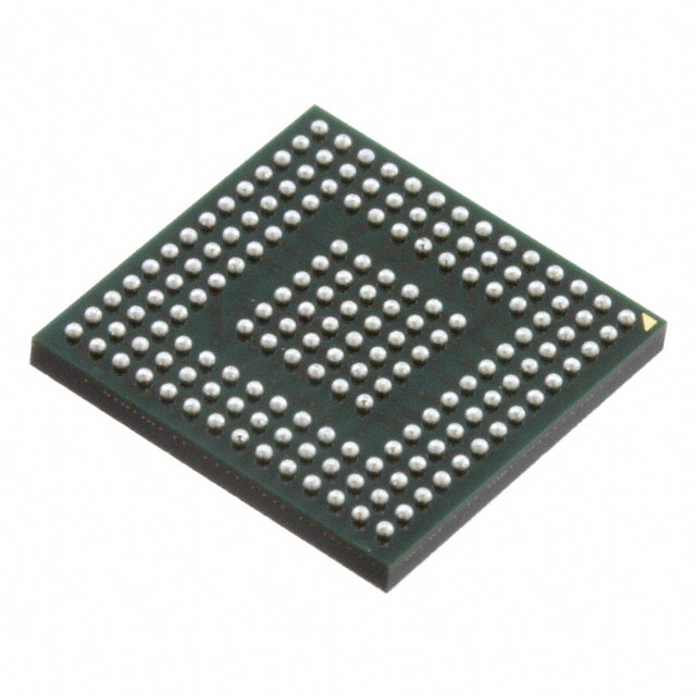
Analog Devices Inc. ADSP-BF514BBCZ-4
- Part No.:
- ADSP-BF514BBCZ-4
- Manufacturer:
- Analog Devices Inc.
- Category:
- DSP (Digital Signal Processors)
- Package:
- 168-LFBGA, CSPBGA
- Datasheet:
-
 ADSP-BF514BBCZ-4.pdf
- Description:
- IC DSP 16/32B 400MHZ 168CSBGA
- Quantity:
- Payment:

- Shipping:

Inventory:2,945
Please send an inquiry. Send us your inquiry, and we will respond immediately.
Product details
Overview
ADSP-BF514BBCZ-4 from Analog Devices is a 400 MHz Blackfin embedded processor with dual 16-bit MACs, 116 KB on-chip memory (32 KB L1 instruction SRAM, 32 KB L1 data SRAM, 4 KB scratchpad), and integrated SPI flash (16 Mbit). It supports IEEE 802.3 10/100 Ethernet MAC only in BF518 variants - not present in ADSP-BF514BBCZ-4 - and features RSI, TWI, two SPORTs, two UARTs, two SPIs, PPI, RTC, watchdog, eight 32-bit timers with PWM, and 40 GPIOs. Used in industrial motor control and networked audio systems requiring deterministic real-time signal processing.
For engineers reviewing the ADSP-BF514BBCZ-4 datasheet, ADSP-BF514BBCZ-4 pinout, ADSP-BF514BBCZ-4 application, or ADSP-BF514BBCZ-4 equivalent, key selection criteria include its 176-lead LQFP_EP package with exposed pad, absence of on-chip Ethernet MAC, presence of RSI for SD/SDIO storage, and 16 Mbit internal SPI flash accessible only via on-die SPI0 signals - not externally routable.
Technical Context
The ADSP-BF514BBCZ-4 implements the Blackfin Micro Signal Architecture (MSA) with a modified Harvard memory model: L1 instruction and data memories operate at full core speed, configurable as SRAM or cache, while external memory access occurs via glueless EBIU supporting SDRAM and asynchronous devices. Its event handling system includes 56 interrupt inputs routed through a hierarchical SIC/CEC structure with nested prioritization.
Peripherals are DMA-accelerated: 12 peripheral DMAs (including dedicated channels for RSI, SPORTs, SPIs, UARTs, PPI) and 2 memory-to-memory DMAs support 1-D/2-D transfers with descriptor-based or register-based initialization. The processor lacks IEEE 1588 or Ethernet MAC functionality - confirmed by Table 1 and General Description - and does not integrate 3-phase PWM hardware despite sharing the same 3-phase PWM unit listing across BF51x family; that unit is present and functional in ADSP-BF514.
Key Specifications
| Parameter | Value and Actual Design Meaning |
|---|---|
| Core Speed | 400 MHz maximum operating frequency - enables real-time execution of dual-MAC audio codecs and motor control algorithms within tight cycle budgets. |
| On-Chip Memory | 116 KB total: 48 KB L1 instruction SRAM (16 KB cache-configurable), 64 KB L1 data SRAM (32 KB ×2 banks), 4 KB scratchpad - eliminates need for external RAM in many embedded signal processing tasks. |
| Internal Flash | 16 Mbit SPI flash integrated inside package, connected exclusively to SPI0 pins - provides secure boot image storage without external flash components or PCB routing. |
| Package | 176-lead LQFP_EP with exposed thermal pad - requires standard QFP reflow profile and thermal vias under pad for junction temperature control below 105°C. |
| I/O Interfaces | RSI (MMC/SD/SDIO/CE-ATA), TWI, 2×SPORT (8 stereo I2S channels), 2×UART (IrDA-capable), 2×SPI, PPI (ITU-R BT.656), 40 GPIO - supports audio streaming, sensor fusion, and removable media in compact industrial designs. |
| Timers & PWM | Eight 32-bit general-purpose timers with PWM output; one 32-bit core timer; one 32-bit counter; 3-phase 16-bit center-aligned PWM unit - directly drives gate drivers in BLDC motor control without external PWM generators. |
| Security | Lockbox secure technology with 64 Kb OTP memory - stores cryptographic keys, device IDs, and MAC addresses in tamper-resistant non-volatile storage programmable once during manufacturing. |
Pinout & Package
ADSP-BF514BBCZ-4 uses a 176-lead LQFP_EP (exposed pad) package measuring 24 mm × 24 mm × 1.4 mm (max), compliant with JEDEC MS-026. Thermal pad must be soldered to PCB ground plane with ≥6 thermal vias (0.3 mm diameter, 1.2 mm pitch) for reliable power dissipation at 400 MHz operation.
| Pin/Terminal | Circuit Role | Design Meaning |
|---|---|---|
| VDDINT | Core supply voltage | 1.2 V ±3% regulated input powering CPU core and L1 memory - requires low-noise 1.2 V regulator with ≤10 mV ripple. |
| VDDIO | I/O supply voltage | 3.3 V ±5% supply for all digital I/O including RSI, SPI, UART, SPORT - tolerant of 1.8 V–3.6 V but configured for 3.3 V in this variant. |
| RESET | Active-low reset input | Asynchronous reset assertion halts core, clears pipelines, and forces boot ROM execution - must be held low ≥100 ns after power stabilization. |
| BOOT_CFG[2:0] | Boot mode configuration | Three-pin strapping inputs determining boot source: internal SPI flash (0b010), OTP (0b001), or external host (0b111) - hardwired at power-on, not runtime reconfigurable. |
| PG11–PG14 | SPI0 interface signals | PG11=SPI0SS, PG12=SPI0SCK, PG13=SPI0MISO, PG14=SPI0MOSI - exclusively connect to internal 16 Mbit flash die; not available as external SPI bus. |
| PH8 | SPI0 chip select alternative | Alternate SPI0SS signal (SEL4 function) - used internally to select flash die; no external routing required or supported. |
Key Features
| Feature | Design Value |
|---|---|
| Dual-MAC + Video ALUs | Two independent 16×16-bit multipliers with 40-bit accumulators plus four 8-bit video ALUs - accelerates MPEG-4 ASP, G.729, and H.264 baseline decoding in single-cycle instructions. |
| Secure Boot & Code Protection | Lockbox technology enforces encrypted boot image verification and prevents unauthorized firmware extraction - critical for medical and industrial firmware integrity compliance. |
| Flexible Memory Mapping | Unified 32-bit address space with MMU-enforced memory protection - isolates RTOS tasks and prevents stack overflow corruption between application and driver layers. |
| Low-Power Dynamic Scaling | Independent voltage/frequency scaling (DVFS) down to 100 MHz/0.9 V - reduces active power by 65% versus full-speed operation while maintaining real-time latency guarantees. |
| Hardware Accelerated DMA | 12 peripheral DMAs + 2 memory DMAs with 2-D descriptor chaining - offloads 100% of audio sample buffering, video frame transfer, and SD card block reads from CPU core. |
Applications
| Industrial Motor Control | Networked Audio Endpoint |
|---|---|
Use Scenario: Closed-loop field-oriented control (FOC) of 3-phase BLDC motors in HVAC compressors and factory automation drives. IC Role / Device Role / Timing Role: Real-time execution of Park/Clarke transforms, PI current regulators, and space-vector PWM generation at 20 kHz switching frequency. Use Value: Integrated 3-phase PWM unit and 400 MHz deterministic core eliminate external PWM ICs and reduce BOM count by 3 components per axis. |
Use Scenario: VoIP speakerphone with echo cancellation, noise suppression, and dual-channel stereo playback/recording over Ethernet. IC Role / Device Role / Timing Role: Simultaneous execution of G.711 codec, acoustic echo canceller (AEC), and RSI-based SD card logging - all within 5 ms audio frame budget. Use Value: On-chip 116 KB SRAM holds full AEC coefficient buffer and dual 16-bit stereo buffers, avoiding external PSRAM and reducing PCB layer count. |
| Medical Imaging Subsystem | Smart Energy Gateway |
Use Scenario: Portable ultrasound beamformer preprocessing: FIR filtering, envelope detection, and log compression before FPGA-based scan conversion. IC Role / Device Role / Timing Role: High-throughput 2-D DMA transfer of ADC samples into L1 data memory, followed by parallel MAC operations on 128-point windows. Use Value: Dual 16-bit MACs process >25 million 16×16 multiply-accumulates per second - sufficient for real-time 15 MHz RF channel processing at 40 MSPS. |
Use Scenario: DIN-rail mounted energy meter gateway aggregating Modbus RTU data from 16 smart meters and forwarding via RSI-connected LTE module. IC Role / Device Role / Timing Role: Concurrent operation of Modbus RTU UART slaves, RSI SDIO host stack, and AES-128 encryption engine using OTP-stored keys. Use Value: Integrated RSI controller and Lockbox OTP eliminate need for external SDIO PHY and secure element IC - certified for IEC 62443-3-3 SL2. |
Equivalent & Alternatives
The following parts are listed as comparable options for similar embedded signal processing applications.
| Alternative Part | Technical Difference | Application Difference | Selection Advice |
|---|---|---|---|
| ADSP-BF516BBCZ-4 | Includes IEEE 802.3 10/100 Ethernet MAC; same core, memory, and peripherals otherwise - no internal SPI flash. | Required for wired Ethernet edge nodes (e.g., building controllers); adds 125 mW typical power and 22 μm larger die size. | Select when deterministic Ethernet connectivity is mandatory and external flash can be added for boot storage. |
| ADSP-BF514BCPZ-4 | Same functional spec but in 168-ball CSP_BGA package (6.0 mm × 6.0 mm); no exposed pad; lower thermal resistance but higher assembly cost. | Suitable for space-constrained portable devices (e.g., handheld test equipment); requires microvias and tighter trace spacing. | Choose for ultra-compact PCBs where thermal pad routing is impractical and volume production justifies CSP_BGA rework capability. |
Compared with ADSP-BF514BBCZ-4, ADSP-BF516BBCZ-4 adds Ethernet MAC at the cost of boot flash and slightly higher power, while ADSP-BF514BCPZ-4 retains identical functionality in a smaller CSP_BGA footprint - making the latter optimal for miniaturized designs and the former for wired infrastructure nodes.
Availability
ADSP-BF514BBCZ-4 is available at Aetrix Electronics and suitable for industrial motor control, networked audio endpoints, medical imaging subsystems, and smart energy gateways requiring stable component supply across 10+ year product lifecycles.
Supply support for ADSP-BF514BBCZ-4 includes scheduled delivery planning, volume procurement assistance, BOM continuity management, traceable sourcing, and lifecycle availability coordination for OEM customers, industrial embedded developers, connected-device designers, and electronics production programs.
Manufacturer
Analog Devices, Inc. is a global semiconductor company specializing in high-performance analog, mixed-signal, and digital signal processing technologies for precision instrumentation, industrial automation, and communications infrastructure.
The Blackfin processor line was designed for embedded applications demanding both real-time signal processing and general-purpose programmability - targeting industrial control, automotive ADAS pre-processing, and professional audio where deterministic latency and code density are critical.
FAQ
Does ADSP-BF514BBCZ-4 include an integrated Ethernet MAC?
No, ADSP-BF514BBCZ-4 does not include an Ethernet MAC. According to Table 1 and the General Description section of the Rev. D datasheet, Ethernet MAC functionality is exclusive to ADSP-BF516, ADSP-BF518, and ADSP-BF518F16 variants. ADSP-BF514BBCZ-4 provides RSI, TWI, UARTs, SPIs, and PPI instead - making it suitable for SDIO-based wireless or cellular connectivity rather than wired Ethernet. This distinction is fixed by silicon design and cannot be enabled via firmware.
What is the purpose of the 16 Mbit SPI flash inside ADSP-BF514BBCZ-4?
The 16 Mbit SPI flash inside ADSP-BF514BBCZ-4 serves as secure, on-package boot memory. It is connected exclusively to the internal SPI0 interface (pins PG11–PG14 and PH8) and cannot be accessed externally. ADSP-BF514BBCZ-4 boots from this flash when BOOT_CFG[2:0] = 0b010, executing the boot kernel stored there. Its contents are write-protected via software-controlled status register bits and support fast sector erase (70 ms typical) and byte-program (15 μs typical).
Can ADSP-BF514BBCZ-4 execute code directly from its internal SPI flash?
No, ADSP-BF514BBCZ-4 cannot execute code directly from internal SPI flash. The flash is accessible only as data memory via SPI0 DMA or programmed I/O - not as executable address space. Code execution occurs from L1 instruction SRAM (32 KB), L3 boot ROM (32 KB), or external SDRAM. The internal flash is used solely for storing boot images, configuration data, or firmware updates loaded into L1/L3 memory at startup.
Is the 3-phase PWM unit present and functional in ADSP-BF514BBCZ-4?
Yes, the 3-phase 16-bit center-aligned PWM unit is fully present and functional in ADSP-BF514BBCZ-4. Table 1 explicitly lists "3-Phase PWM Pairs" as "3" for all BF51x variants including BF514, and the General Description confirms inclusion of "3-phase 16-bit center-based PWM unit" in the peripheral set. This hardware block generates six complementary PWM outputs with dead-time insertion and fault protection - essential for driving 3-phase inverter bridges in motor control applications.
What boot sources does ADSP-BF514BBCZ-4 support besides internal SPI flash?
ADSP-BF514BBCZ-4 supports four boot sources determined by BOOT_CFG[2:0] strapping pins: internal SPI flash (0b010), OTP memory (0b001), external SPI/parallel memories via EBIU (0b100), or host device via SPI/UART (0b111). The boot kernel resides in 32 KB L3 ROM and configures the selected interface before loading the application image. External boot modes require external memory devices and correct timing setup per the Electrical Characteristics table on page 24 of the datasheet.
ADSP-BF514BBCZ-4 Specifications
- Product attributes
- Attribute value
- Manufacturer:
- Analog Devices Inc.
- Series:
- Blackfin®
- Package/Case:
- 168-LFBGA, CSPBGA
- Packaging:
- Tray
- Product Status:
- Active
- Type:
- Fixed Point
- Interface:
- I2C, PPI, RSI, SPI, SPORT, UART/USART
- Clock Rate:
- 400MHz
- Non-Volatile Memory:
- External
- On-Chip RAM:
- 116kB
- Voltage - I/O:
- 1.8V, 2.5V, 3.3V
- Voltage - Core:
- 1.30V
- Operating Temperature:
- -40°C ~ 85°C (TA)
- Grade:
- -
- Qualification:
- -
- Mounting Type:
- Surface Mount
- Supplier Device Package:
- 168-CSPBGA (12x12)
ADSP-BF514BBCZ-4 FAQ
1.How can I place an order for ADSP-BF514BBCZ-4 through Aetrix?
Please submit a Request for Quotation (RFQ) for ADSP-BF514BBCZ-4 on Aetrix. Our sales agent will provide a competitive quotation and guide you through the order confirmation once you accept the terms.
2.Are the price and stock information for ADSP-BF514BBCZ-4 reliable?
The price and inventory of ADSP-BF514BBCZ-4 are updated periodically and may fluctuate due to market conditions. Stock and pricing data are typically refreshed every 24 hours. Quotation validity for ADSP-BF514BBCZ-4 is usually 5 days.
3.What payment methods are accepted for ADSP-BF514BBCZ-4?
We accept Wire Transfer, PayPal, Credit Card, Western Union, MoneyGram, and Escrow for ADSP-BF514BBCZ-4 transactions.
Note: Certain payment methods may incur a processing fee.
4.How is shipping managed for ADSP-BF514BBCZ-4?
ADSP-BF514BBCZ-4 orders can be shipped via leading logistics carriers, including DHL, UPS, FedEx, TNT, or Registered Mail.
Once your ADSP-BF514BBCZ-4 order is processed, you will receive an email with the shipment details and tracking number.
Note: Tracking information may take up to 24 hours to appear. Express delivery typically takes 3–5 business days.
5.How can I obtain technical support or documentation for ADSP-BF514BBCZ-4?
For technical support, including ADSP-BF514BBCZ-4 datasheets, pinout diagrams, or application guidance, please contact our engineering support team. They can provide detailed documentation and assistance for your ADSP-BF514BBCZ-4 requirements.
6.How does Aetrix verify that ADSP-BF514BBCZ-4 is sourced from the original manufacturer or authorized distributors?
All ADSP-BF514BBCZ-4 products on Aetrix are procured from qualified distributors and authorized channels. Our dedicated quality assurance team conducts strict verification, including traceability checks and, if necessary, third-party testing. This ensures that ADSP-BF514BBCZ-4 meets industry standards.
7.What is the process for return or replacement of ADSP-BF514BBCZ-4?
All ADSP-BF514BBCZ-4 units undergo pre-shipment inspection (PSI). If there is an issue with ADSP-BF514BBCZ-4, returns or replacements are accepted under the following conditions:
1.Quantity discrepancies, incorrect items, or visible external defects (such as breakage or corrosion), acknowledged by Aetrix.
2.The issue is reported within 90 days of delivery.
3.The ADSP-BF514BBCZ-4 part is unused and in its original packaging.
Return procedure for ADSP-BF514BBCZ-4:
1.Submit a request within 90 days.
2.Obtain a Return Material Authorization (RMA) from Aetrix.
ADSP-BF514BBCZ-4 Tags
-
TMS320C5535AZAY10
Texas Instruments
-
TMS320VC5501PGF300
Texas Instruments
-
ADSP-BF592KCPZ
Analog Devices Inc.
-
ADAU1463WBCPZ150
Analog Devices Inc.
-
TMS320VC5402PGE100
Texas Instruments
-
ADAU1701JSTZ-RL
Analog Devices Inc.
-
ADAU1701JSTZ
Analog Devices Inc.
-
TMS320VC5502PGF300
Texas Instruments
-
ADAU1462WBCPZ300RL
Analog Devices Inc.
-
ADAU1452KCPZRL
Analog Devices Inc.
-
ADAU1452WBCPZ-RL
Analog Devices Inc.
-
TMS320C6747DZKB3
Texas Instruments
Tech Hub

A practical engineering guide to 3.3V and 5V logic compatibility, input thresholds, resistor dividers, translator ICs, MOSFET level shifting, I2C pull-ups, timing limits and power-sequencing risks.

The 74HC595 uses push-pull logic outputs, while the TPIC6B595 uses 50 V open-drain DMOS sinks for higher-power loads. This guide compares timing, current limits, 3.3 V interfacing, load wiring, thermal…

The 74HC595 converts serial data into eight stable parallel outputs. This guide covers pin functions, shift and storage timing, OE and MR behavior, drive-current limits, cascading, voltage compatibilit…

A technical comparison of level-sensitive latches and edge-triggered flip-flops, covering timing windows, setup and hold limits, master–slave operation, time borrowing, race-through, HDL inference and…

A D latch stores one bit while Enable controls when data can pass. This reference covers gate-level operation, truth tables, transparency, setup and hold timing, LE versus OE, common ICs and practical …

An SR latch stores one bit through cross-coupled feedback. This engineering reference covers NOR and NAND implementations, truth tables, forbidden-state recovery, gated operation, switch debouncing, fa…

Latch circuits retain one bit through feedback. This technical reference covers SR and D latches, truth tables, transparency, timing limits, latch-versus-flip-flop behavior, applications and common log…

An engineering guide to LED driver operation, constant-current and constant-voltage outputs, linear and switching topologies, dimming, IC selection, calculations, replacement compatibility, and fault c…

Operational amplifier guide covering op amp basics, feedback, ideal vs real op amps, common configurations, buffer circuits, offset, bias current, gain-bandwidth, slew rate, rail-to-rail limits and sel…

Jumper cables guide covering safe connection order, red and black clamp placement, final ground connection, cable gauge, length, clamp quality, copper vs CCA cables, jump starter comparison and battery…


