
 My Inquiry
 My Account


Analog Devices Inc. ADSP-BF532SBBC400
- Part No.:
- ADSP-BF532SBBC400
- Manufacturer:
- Analog Devices Inc.
- Category:
- DSP (Digital Signal Processors)
- Package:
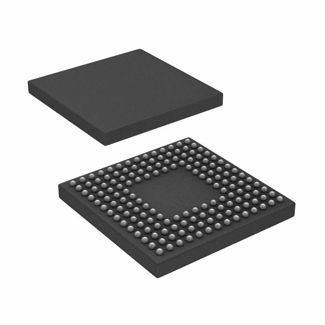
- 160-LFBGA, CSPBGA
- Datasheet:
-
 ADSP-BF532SBBC400.pdf
- Description:
- IC DSP CTLR 16B 400MHZ 160CSBGA
- Quantity:
- Payment:

- Shipping:

Inventory:4,341
Please send an inquiry. Send us your inquiry, and we will respond immediately.
Product details
Overview
ADSP-BF532SBBC400 from Analog Devices is a Blackfin embedded processor with dual 16-bit MACs, two 40-bit ALUs, and 40-bit shifter, operating at 400 MHz. It integrates 16 KB L1 instruction SRAM, 32 KB L1 data SRAM, and 4 KB scratchpad SRAM, supporting real-time audio/video processing in portable industrial controllers.
For engineers reviewing the ADSP-BF532SBBC400 datasheet, ADSP-BF532SBBC400 pinout, ADSP-BF532SBBC400 application, or ADSP-BF532SBBC400 equivalent, key selection criteria include on-chip memory configuration (16K/32K/4K), 160-ball CSP_BGA package compatibility, dynamic voltage/frequency scaling support, and PPI/SPI/SPORT peripheral integration for multimedia signal chains.
Technical Context
The ADSP-BF532SBBC400 implements a modified Harvard architecture with hierarchical L1 memory (instruction/data/scratchpad), MMU-based memory protection, and glueless external memory controller supporting SDRAM, SRAM, flash, and ROM. Its core features RISC-like register model and algebraic assembly syntax optimized for C/C++ compilation.
Peripherals include parallel peripheral interface (PPI) compliant with ITU-R 656 video formats, two dual-channel full-duplex SPORTs supporting eight stereo I²S channels, three 32-bit timers with PWM, UART with IrDA, and on-chip PLL for frequency multiplication - all interconnected via high-bandwidth DMA buses running up to 133 MHz.
Key Specifications
| Parameter | Value and Actual Design Meaning |
|---|---|
| Core Speed | 400 MHz maximum operation - enables real-time execution of complex DSP algorithms within tight latency budgets. |
| L1 Instruction Memory | 16 KB SRAM - provides zero-wait-state instruction fetch at full core speed for deterministic code execution. |
| L1 Data Memory | 32 KB SRAM - supports simultaneous dual-fetch addressing for high-throughput data processing pipelines. |
| Scratchpad SRAM | 4 KB dedicated stack/local variable storage - eliminates cache coherency overhead in critical real-time tasks. |
| MAC Units | Dual 16×16-bit multipliers with 40-bit accumulators - delivers 800 MMAC/s throughput for FIR/IIR filtering and FFT kernels. |
| Package | 160-ball CSP_BGA - enables compact PCB layout for space-constrained portable and automotive control modules. |
| Power Management | On-chip programmable voltage regulator with dynamic V/F scaling - reduces active power consumption by >40% versus fixed-voltage operation. |
Pinout & Package
ADSP-BF532SBBC400 is housed in a 160-ball CSP_BGA package with 0.5 mm pitch, designed for high-density routing and thermal performance in embedded systems. Ball assignments follow JEDEC MO-220 standard with defined power/ground distribution and signal integrity optimization.
| Pin/Terminal | Circuit Role | Design Meaning |
|---|---|---|
| VDDEXT | External supply input | Provides 2.5–3.6 V to on-chip voltage regulator - determines core voltage range and dynamic scaling capability. |
| VDDINT | Core supply output | Regulated core voltage (typically 1.2–1.4 V) delivered to processor logic - directly impacts power/performance trade-off. |
| CLKIN | External clock input | Accepts 1–50 MHz crystal or oscillator reference - feeds on-chip PLL for internal 400 MHz clock generation. |
| PPI[15:0] | Parallel Peripheral Interface bus | 16-bit bidirectional video/data interface compliant with ITU-R 656 - enables direct connection to image sensors or display controllers. |
| SPORT0_DA/DB | Synchronous serial port data | Dual-channel full-duplex I²S/AC97 interface - supports concurrent stereo audio capture and playback without CPU intervention. |
| GPIO_F[15:0] | General-purpose I/O bank | 16 configurable pins with interrupt capability - used for system control signals, status monitoring, or hardware handshaking. |
Key Features
| Feature | Design Value |
|---|---|
| Dual-MAC + SIMD video ALUs | Enables concurrent signal processing and multimedia operations - accelerates video encoding, voice recognition, and motor control loops. |
| Memory management unit (MMU) | Provides per-task memory protection - isolates firmware partitions in safety-critical applications like automotive ECUs. |
| Glueless external memory controller | Eliminates address latching and timing logic for SDRAM/SRAM/flash - reduces BOM cost and PCB layer count. |
| Real-time clock + watchdog timer | Supports time-stamped event logging and fail-safe system recovery - essential for unattended industrial gateways. |
| JTAG debug interface with trace | Enables non-intrusive instruction-level debugging and performance profiling - accelerates firmware validation in complex signal chains. |
Applications
| Industrial Motor Control | Portable Audio Decoder |
|---|---|
Use Scenario: Closed-loop servo drive with field-oriented control and current sensing feedback. IC Role / Device Role / Timing Role: Real-time DSP engine executing PWM generation, Clarke/Park transforms, and PID regulation at 20 kHz loop rate. Use Value: Dual 16-bit MACs deliver deterministic 800 MMAC/s throughput while L1 SRAM ensures sub-microsecond memory access for jitter-free motor timing. | Use Scenario: Battery-powered MP3/WMA player with LCD display and SD card interface. IC Role / Device Role / Timing Role: Audio codec processor handling decoding, equalization, volume control, and I²S output to DAC. Use Value: Dynamic voltage/frequency scaling extends battery life by 35% during low-workload playback; PPI supports direct LCD frame buffer access. |
| Automotive Camera Module | Smart Energy Meter |
Use Scenario: Rear-view camera with NTSC/PAL video capture and on-board image enhancement. IC Role / Device Role / Timing Role: Video front-end processor performing auto-exposure, white balance, and edge enhancement before transmission. Use Value: ITU-R 656-compliant PPI accepts raw sensor data at 27 MHz; 40-bit shifter enables fast normalization for histogram-based AE algorithms. | Use Scenario: DIN-rail mounted meter with harmonic analysis, tamper detection, and RS-485 communication. IC Role / Device Role / Timing Role: Measurement engine computing RMS, THD, and power factor using sampled voltage/current waveforms. Use Value: On-chip RTC timestamps events for compliance reporting; SPI interface connects to isolated RS-485 transceiver without external logic. |
Equivalent & Alternatives
The following parts are listed as comparable options for similar embedded DSP processor applications.
| Alternative Part | Technical Difference | Application Difference | Selection Advice |
|---|---|---|---|
| ADSP-BF531SBBC400 | Identical 400 MHz speed and 160-ball CSP_BGA package, but reduced L1 data memory (16 KB vs. 32 KB). | Suitable for simpler audio codecs or sensor fusion where <24 KB working memory suffices. | Select when application memory footprint fits within 16 KB L1 data SRAM and cost reduction is prioritized. |
| ADSP-BF533SBBC600 | Same architecture and peripherals, but rated for 600 MHz operation and larger L1 instruction memory (64 KB vs. 16 KB). | Required for computationally intensive tasks like multi-channel audio mixing or real-time video analytics. | Choose when algorithm complexity exceeds ADSP-BF532SBBC400's 400 MHz throughput or requires >16 KB instruction cache. |
Compared with ADSP-BF532SBBC400, ADSP-BF531SBBC400 offers identical timing and pinout at lower memory cost, while ADSP-BF533SBBC600 provides higher compute density and expanded instruction space - both maintain full code compatibility but differ in memory bandwidth and thermal envelope.
Availability
ADSP-BF532SBBC400 is available at Aetrix Electronics and suitable for industrial motor control, portable audio decoding, automotive camera modules, and smart energy metering requiring stable component supply across extended product lifecycles.
Supply support for ADSP-BF532SBBC400 includes scheduled delivery planning, volume procurement assistance, BOM continuity management, traceable sourcing, and lifecycle availability coordination for OEM customers, industrial embedded developers, connected-device designers, and electronics production programs.
Manufacturer
Analog Devices, Inc. is a global semiconductor leader specializing in high-performance analog, mixed-signal, and digital signal processing technologies for precision instrumentation and real-time systems.
The Blackfin family, including ADSP-BF532SBBC400, was designed for cost-sensitive embedded applications demanding combined microcontroller programmability and DSP performance - especially in portable, automotive, and industrial control domains.
FAQ
What is the maximum operating frequency of the ADSP-BF532SBBC400?
The ADSP-BF532SBBC400 is rated for a maximum core clock frequency of 400 MHz. This speed grade is guaranteed under specified operating conditions including VDDINT = 1.25 V ± 3%, ambient temperature ≤ 85°C, and proper PCB thermal design. The on-chip PLL multiplies an external CLKIN signal to achieve this frequency, and the device maintains full functionality across its entire 400 MHz operational range as validated in Analog Devices' Rev. I datasheet.
Does the ADSP-BF532SBBC400 support booting from external flash memory?
Yes, the ADSP-BF532SBBC400 supports flexible booting from external flash memory via its asynchronous memory controller. The processor initializes using an on-chip boot kernel that configures the EBIU to access flash devices in Bank 0–3, with programmable timing parameters for diverse flash types. Boot mode is selected via hardware strapping pins (BOOT_CFG[2:0]), and the device executes code directly from flash without requiring copy-to-RAM, enabling secure and fast startup in industrial gateways and automotive modules using ADSP-BF532SBBC400.
How much on-chip memory does the ADSP-BF532SBBC400 provide?
The ADSP-BF532SBBC400 integrates 16 KB of L1 instruction SRAM, 32 KB of L1 data SRAM, and 4 KB of dedicated scratchpad SRAM - totaling 52 KB of zero-wait-state on-chip memory. Unlike the ADSP-BF531SBBC400 (16 KB data) or ADSP-BF533SBBC600 (64 KB instruction), this configuration balances instruction density and data throughput for mid-tier real-time applications. All memory blocks operate at full core speed and are accessible via separate high-bandwidth buses as documented in the ADSP-BF532SBBC400 memory map on page 4 of the datasheet.
Is the ADSP-BF532SBBC400 pin-compatible with other Blackfin processors?
Yes, the ADSP-BF532SBBC400 is fully pin-compatible with ADSP-BF531SBBC400 and ADSP-BF533SBBC600 in the same 160-ball CSP_BGA package variant. This includes identical ball assignments for power, ground, clocks, memory interfaces, and peripherals such as PPI, SPORTs, SPI, and GPIO_F. Pin compatibility enables drop-in replacement during design iteration or performance scaling, provided PCB layout accommodates thermal and decoupling requirements specific to each speed grade - a key advantage confirmed in Table 1 and Pin Descriptions section of the ADSP-BF532SBBC400 datasheet.
What development tools are supported for the ADSP-BF532SBBC400?
Analog Devices provides complete toolchain support for the ADSP-BF532SBBC400, including VisualDSP++ IDE with C/C++ compiler, assembler, and linker optimized for Blackfin architecture; EZ-KIT Lite evaluation boards with JTAG emulator; and libraries for FFT, FIR, and audio codecs. The processor's JTAG interface supports real-time trace, hardware breakpoints, and performance monitoring - enabling rapid firmware development for applications ranging from motor control to voice processing using ADSP-BF532SBBC400 as the central signal processor.
ADSP-BF532SBBC400 Specifications
- Product attributes
- Attribute value
- Manufacturer:
- Analog Devices Inc.
- Series:
- Blackfin®
- Package/Case:
- 160-LFBGA, CSPBGA
- Packaging:
- Tray
- Product Status:
- Obsolete
- Type:
- Fixed Point
- Interface:
- SPI, SSP, UART
- Clock Rate:
- 400MHz
- Non-Volatile Memory:
- ROM (1kB)
- On-Chip RAM:
- 84kB
- Voltage - I/O:
- 3.30V
- Voltage - Core:
- 1.20V
- Operating Temperature:
- -40°C ~ 85°C (TA)
- Grade:
- -
- Qualification:
- -
- Mounting Type:
- Surface Mount
- Supplier Device Package:
- 160-CSPBGA (12x12)
ADSP-BF532SBBC400 FAQ
1.How can I place an order for ADSP-BF532SBBC400 through Aetrix?
Please submit a Request for Quotation (RFQ) for ADSP-BF532SBBC400 on Aetrix. Our sales agent will provide a competitive quotation and guide you through the order confirmation once you accept the terms.
2.Are the price and stock information for ADSP-BF532SBBC400 reliable?
The price and inventory of ADSP-BF532SBBC400 are updated periodically and may fluctuate due to market conditions. Stock and pricing data are typically refreshed every 24 hours. Quotation validity for ADSP-BF532SBBC400 is usually 5 days.
3.What payment methods are accepted for ADSP-BF532SBBC400?
We accept Wire Transfer, PayPal, Credit Card, Western Union, MoneyGram, and Escrow for ADSP-BF532SBBC400 transactions.
Note: Certain payment methods may incur a processing fee.
4.How is shipping managed for ADSP-BF532SBBC400?
ADSP-BF532SBBC400 orders can be shipped via leading logistics carriers, including DHL, UPS, FedEx, TNT, or Registered Mail.
Once your ADSP-BF532SBBC400 order is processed, you will receive an email with the shipment details and tracking number.
Note: Tracking information may take up to 24 hours to appear. Express delivery typically takes 3–5 business days.
5.How can I obtain technical support or documentation for ADSP-BF532SBBC400?
For technical support, including ADSP-BF532SBBC400 datasheets, pinout diagrams, or application guidance, please contact our engineering support team. They can provide detailed documentation and assistance for your ADSP-BF532SBBC400 requirements.
6.How does Aetrix verify that ADSP-BF532SBBC400 is sourced from the original manufacturer or authorized distributors?
All ADSP-BF532SBBC400 products on Aetrix are procured from qualified distributors and authorized channels. Our dedicated quality assurance team conducts strict verification, including traceability checks and, if necessary, third-party testing. This ensures that ADSP-BF532SBBC400 meets industry standards.
7.What is the process for return or replacement of ADSP-BF532SBBC400?
All ADSP-BF532SBBC400 units undergo pre-shipment inspection (PSI). If there is an issue with ADSP-BF532SBBC400, returns or replacements are accepted under the following conditions:
1.Quantity discrepancies, incorrect items, or visible external defects (such as breakage or corrosion), acknowledged by Aetrix.
2.The issue is reported within 90 days of delivery.
3.The ADSP-BF532SBBC400 part is unused and in its original packaging.
Return procedure for ADSP-BF532SBBC400:
1.Submit a request within 90 days.
2.Obtain a Return Material Authorization (RMA) from Aetrix.
ADSP-BF532SBBC400 Tags
-
TMS320C5535AZAY10
Texas Instruments
-
TMS320VC5501PGF300
Texas Instruments
-
ADSP-BF592KCPZ
Analog Devices Inc.
-
ADAU1463WBCPZ150
Analog Devices Inc.
-
TMS320VC5402PGE100
Texas Instruments
-
ADAU1701JSTZ-RL
Analog Devices Inc.
-
ADAU1701JSTZ
Analog Devices Inc.
-
TMS320VC5502PGF300
Texas Instruments
-
ADAU1462WBCPZ300RL
Analog Devices Inc.
-
ADAU1452KCPZRL
Analog Devices Inc.
-
ADAU1452WBCPZ-RL
Analog Devices Inc.
-
TMS320C6747DZKB3
Texas Instruments
Tech Hub

A practical engineering guide to 3.3V and 5V logic compatibility, input thresholds, resistor dividers, translator ICs, MOSFET level shifting, I2C pull-ups, timing limits and power-sequencing risks.

The 74HC595 uses push-pull logic outputs, while the TPIC6B595 uses 50 V open-drain DMOS sinks for higher-power loads. This guide compares timing, current limits, 3.3 V interfacing, load wiring, thermal…

The 74HC595 converts serial data into eight stable parallel outputs. This guide covers pin functions, shift and storage timing, OE and MR behavior, drive-current limits, cascading, voltage compatibilit…

A technical comparison of level-sensitive latches and edge-triggered flip-flops, covering timing windows, setup and hold limits, master–slave operation, time borrowing, race-through, HDL inference and…

A D latch stores one bit while Enable controls when data can pass. This reference covers gate-level operation, truth tables, transparency, setup and hold timing, LE versus OE, common ICs and practical …

An SR latch stores one bit through cross-coupled feedback. This engineering reference covers NOR and NAND implementations, truth tables, forbidden-state recovery, gated operation, switch debouncing, fa…

Latch circuits retain one bit through feedback. This technical reference covers SR and D latches, truth tables, transparency, timing limits, latch-versus-flip-flop behavior, applications and common log…

An engineering guide to LED driver operation, constant-current and constant-voltage outputs, linear and switching topologies, dimming, IC selection, calculations, replacement compatibility, and fault c…

Operational amplifier guide covering op amp basics, feedback, ideal vs real op amps, common configurations, buffer circuits, offset, bias current, gain-bandwidth, slew rate, rail-to-rail limits and sel…

Jumper cables guide covering safe connection order, red and black clamp placement, final ground connection, cable gauge, length, clamp quality, copper vs CCA cables, jump starter comparison and battery…


