
 My Inquiry
 My Account


Analog Devices Inc. ADSP-BF705BBCZ-4
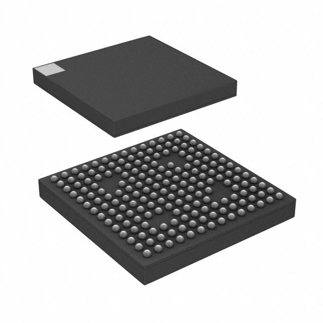
- Part No.:
- ADSP-BF705BBCZ-4
- Manufacturer:
- Analog Devices Inc.
- Category:
- DSP (Digital Signal Processors)
- Package:
- 184-LFBGA, CSPBGA
- Datasheet:
-
 ADSP-BF705BBCZ-4.pdf
- Description:
- IC DSP LP 512KB L2SR 184BGA
- Quantity:
- Payment:

- Shipping:

Inventory:2,029
Please send an inquiry. Send us your inquiry, and we will respond immediately.
Product details
Overview
ADSP-BF705BBCZ-4 from Analog Devices is a Blackfin+ embedded processor with 400 MHz core frequency, dual 16-bit or single 32-bit MAC per cycle, 136 kB parity-protected L1 SRAM (64 kB instruction + 64 kB data + 8 kB scratchpad), 512 kB ECC-protected L2 SRAM, and AEC-Q100 qualification for automotive use. It integrates two CAN 2.0B controllers, USB 2.0 HS OTG, dual UARTs, and hardware crypto acceleration for secure boot and runtime encryption.
For engineers reviewing the ADSP-BF705BBCZ-4 datasheet, ADSP-BF705BBCZ-4 pinout, ADSP-BF705BBCZ-4 application, or ADSP-BF705BBCZ-4 equivalent, key selection criteria include L2 SRAM size (512 kB), 184-ball CSP_BGA RoHS-compliant package, 2× CAN + USB 2.0 HS OTG peripheral set, Blackfin+ instruction set compatibility, and automotive-grade thermal/power specifications at 400 MHz.
Technical Context
The ADSP-BF705BBCZ-4 implements a modified Harvard architecture with separate 64 kB L1 instruction and 64 kB L1 data SRAM blocks-both multi-parity-bit protected-and an 8 kB scratchpad. Its Blackfin+ core executes two 16×16 MACs or one 32×32 MAC per cycle, supports 16-bit complex MAC, and includes branch prediction and cache enhancements while maintaining full instruction-set compatibility with prior Blackfin processors.
Memory hierarchy includes 512 kB ECC-protected unified L2 SRAM, 512 kB on-chip ROM, and a 16-bit L3 interface (CSP_BGA only) supporting DDR2/LPDDR up to 200 MHz. Peripherals include dual CAN 2.0B controllers with message objects, USB 2.0 HS OTG with integrated PHY, two 8-channel GP timers, RTC, and hardware crypto accelerators for AES/SHA/DES with memDMA encryption/decryption.
Key Specifications
| Parameter | Value and Actual Design Meaning |
|---|---|
| Core Architecture | Blackfin+ 32-bit RISC/DSP hybrid with dual-MAC, SIMD, and orthogonal instruction set |
| Max Core Frequency | 400 MHz - enables real-time audio/video processing and motor control loop execution at ≤2.5 μs latency |
| L1 Memory | 136 kB total: 64 kB instruction SRAM + 64 kB data SRAM + 8 kB scratchpad, all multi-parity-bit protected |
| L2 Memory | 512 kB ECC-protected SRAM - provides error-correcting code for safety-critical automotive firmware storage |
| Package | 184-ball CSP_BGA, 12 mm × 12 mm × 0.8 mm pitch, RoHS compliant - supports high-density PCB layouts with thermal vias |
| Automotive Qualification | AEC-Q100 Grade 3 (−40°C to +125°C) - validated for engine control, ADAS sensor fusion, and infotainment head units |
| Peripherals | 2× CAN 2.0B, USB 2.0 HS OTG, 2× UART, 2× SPORT, PPI, MSI (SD/SDIO), TWI, 8× timer, RTC, crypto engine |
Pinout & Package
ADSP-BF705BBCZ-4 uses a 184-ball CSP_BGA package (12 mm × 12 mm, 0.8 mm pitch), RoHS compliant, with ball assignments defined in Analog Devices' ADSP-BF70x documentation (Rev. D, Pages 105–107). The package supports thermal dissipation via exposed die pad and enables high-speed signal routing for DDR2/LPDDR and USB 2.0 HS interfaces.
| Pin/Terminal | Circuit Role | Design Meaning |
|---|---|---|
| VDD_INT | Core power supply | 1.05 V ±3% supply for 400 MHz operation; requires low-noise decoupling near package |
| VDD_EXT | I/O and peripheral power | 3.3 V or 1.8 V selectable; powers USB PHY, CAN transceivers, and GPIO banks |
| CLKIN | External clock input | Accepts 1–50 MHz crystal or CMOS clock; feeds PLL for SYSCLK generation up to 400 MHz |
| RESET | Active-low reset input | Synchronous deassertion required; initiates secure boot sequence from L2 ROM or external memory |
| USB_DP / USB_DM | USB 2.0 HS differential pair | Integrated PHY supports host/device/OTG modes; requires 90 Ω differential impedance routing |
| CAN0_TX / CAN0_RX | CAN 2.0B controller channel 0 | Direct connection to external CAN transceiver; supports bit rates up to 1 Mbps with programmable timing |
| BOOT_CFG[2:0] | Boot mode configuration | Three-pin strap determines boot source: SPI flash, parallel NOR, USB, or UART - no external pull-up needed |
Key Features
| Feature | Design Value |
|---|---|
| Dual 16-bit or single 32-bit MAC/cycle | Enables simultaneous real-time filtering and FFT computation without cycle-stalling - critical for active noise cancellation |
| Hardware crypto engine | Accelerates AES-128/256, SHA-256, DES/3DES, and RSA key generation - reduces secure boot time to <100 ms |
| memDMA encryption/decryption | Performs transparent AES-CTR encryption on DMA transfers between L2 SRAM and peripherals - secures sensor data in motion |
| 512 kB ECC-protected L2 SRAM | Corrects single-bit errors and detects double-bit errors in firmware/data - meets ASIL-B functional safety requirements |
| AEC-Q100 Grade 3 qualification | Validated across −40°C to +125°C junction temperature range with HTOL and TC testing - suitable for under-hood ECUs |
Applications
| Automotive Engine Control Unit (ECU) | Industrial Motor Drive Controller |
|---|---|
Use Scenario: Real-time combustion timing, fuel injection pulse width modulation, and OBD-II diagnostics in gasoline/diesel powertrain systems. IC Role / Device Role / Timing Role: Primary compute engine executing PID loops, sensor fusion (crank/cam position, knock, O2), and CAN-based actuator command dispatch at ≤100 μs jitter. Use Value: 400 MHz Blackfin+ core with dual MAC delivers deterministic 50 kHz control loop execution; 2× CAN interfaces enable concurrent powertrain and chassis network communication. | Use Scenario: Closed-loop vector control of 3-phase AC induction or BLDC motors in HVAC compressors, pumps, and factory automation drives. IC Role / Device Role / Timing Role: Real-time field-oriented control (FOC) processor handling Clarke/Park transforms, PWM generation, and current sensing ADC synchronization. Use Value: 136 kB L1 SRAM stores FOC lookup tables and filter coefficients; hardware crypto secures firmware updates over CAN or USB during field servicing. |
| Secure Biometric Access Terminal | Medical Ultrasound Beamformer |
Use Scenario: Fingerprint/vein pattern matching and encrypted credential storage in physical access control panels deployed in hospitals and data centers. IC Role / Device Role / Timing Role: Trusted execution environment managing biometric template comparison, OTP-secured key storage, and TLS-secured network enrollment. Use Value: One-time-programmable (OTP) memory stores unique chip ID and root keys; memDMA encryption protects biometric templates during DRAM transfer. | Use Scenario: Digital beamforming and RF echo processing in portable ultrasound systems requiring low-power, high-SNR signal conditioning. IC Role / Device Role / Timing Role: High-throughput DSP engine performing FIR filtering, envelope detection, and log compression on 12-bit ADC streams from 64+ channels. Use Value: Dual 16-bit MACs process 128-sample FIR kernels in <500 ns; 512 kB L2 SRAM buffers raw RF data for real-time B-mode image reconstruction. |
Equivalent & Alternatives
The following parts are listed as comparable options for similar embedded DSP processor applications.
| Alternative Part | Technical Difference | Application Difference | Selection Advice |
|---|---|---|---|
| ADSP-BF706BBCZ-4 | 1 MB L2 SRAM (vs. 512 kB), same 184-ball CSP_BGA package and peripheral set | Preferred for applications requiring larger firmware images or extended data buffering (e.g., multi-sensor fusion with logging) | Select when >512 kB L2 SRAM is mandatory; identical pinout and software compatibility reduce migration effort |
| ADSP-BF703BBCZ-4 | 256 kB L2 SRAM, 88-lead LFCSP_VQ (12 mm × 12 mm), no L3 DDR2/LPDDR interface | Suitable for cost-sensitive, space-constrained designs where external DRAM is unnecessary (e.g., standalone CAN gateway) | Choose for lower BOM cost and simpler layout; verify peripheral count (e.g., missing USB 2.0 HS OTG) matches system needs |
Compared with ADSP-BF705BBCZ-4, ADSP-BF706BBCZ-4 offers double L2 SRAM capacity for larger algorithm footprints, while ADSP-BF703BBCZ-4 trades L2 size and DRAM interface for smaller footprint and lower cost - both retain identical Blackfin+ core performance and CAN/UART peripheral functionality.
Availability
ADSP-BF705BBCZ-4 is available at Aetrix Electronics and suitable for automotive ECU development, industrial motor drive design, and secure biometric terminal production requiring stable component supply and long-term lifecycle support.
Supply support for ADSP-BF705BBCZ-4 includes scheduled delivery planning, volume procurement assistance, BOM continuity management, traceable sourcing, and lifecycle availability coordination for OEM customers, industrial embedded developers, connected-device designers, and electronics production programs.
Manufacturer
Analog Devices, Inc. is a global semiconductor company specializing in high-performance analog, mixed-signal, and digital signal processing technologies for precision measurement and connectivity.
The ADSP-BF70x product line delivers scalable Blackfin+ processors optimized for real-time embedded applications demanding deterministic DSP performance, functional safety, and hardware security - especially in automotive, industrial, and medical edge devices.
FAQ
What is the maximum operating frequency of the ADSP-BF705BBCZ-4?
The ADSP-BF705BBCZ-4 operates at a maximum core frequency of 400 MHz. This speed grade is validated across the full AEC-Q100 Grade 3 temperature range (−40°C to +125°C junction), with core power supply (VDD_INT) specified at 1.05 V ±3%. At this frequency, the Blackfin+ core delivers dual 16-bit MAC operations per cycle and supports real-time execution of complex control algorithms and signal processing tasks.
Does the ADSP-BF705BBCZ-4 support external DDR2 or LPDDR memory?
Yes, the ADSP-BF705BBCZ-4 supports external DDR2 and LPDDR SDRAM through its dedicated 16-bit L3 interface - but only in the 184-ball CSP_BGA package variant. This interface operates up to 200 MHz and is JESD79-2E and JESD209A compliant. The 88-lead LFCSP package does not include this interface. System design must implement proper termination, length matching, and power integrity for reliable high-speed DRAM operation.
How is security implemented in the ADSP-BF705BBCZ-4?
The ADSP-BF705BBCZ-4 implements security via hardware crypto accelerators (AES-128/256, SHA-256, DES/3DES), 1 kB one-time-programmable (OTP) memory for unique chip ID and root keys, fast secure boot from L2 ROM, and memDMA encryption/decryption for runtime data protection. These features collectively enable secure firmware authentication, encrypted firmware updates, and tamper-resistant biometric template storage - meeting requirements for automotive and medical device certifications.
What package type is used for the ADSP-BF705BBCZ-4?
The ADSP-BF705BBCZ-4 uses a 184-ball CSP_BGA package measuring 12 mm × 12 mm with 0.8 mm ball pitch and RoHS compliance. This package includes an exposed thermal pad for enhanced heat dissipation and supports high-density routing for USB 2.0 HS, CAN, and DDR2/LPDDR interfaces. Pin assignments and solder mask recommendations are documented in Analog Devices' ADSP-BF70x datasheet Rev. D, Pages 105–107.
Which peripherals are integrated into the ADSP-BF705BBCZ-4?
The ADSP-BF705BBCZ-4 integrates two CAN 2.0B controllers, USB 2.0 HS OTG with integrated PHY, two UARTs, two SPORTs, PPI, MSI (SD/SDIO), TWI, RTC, eight general-purpose timers, watchdog timer, up/down/rotary counter, quad SPI, dual SPI, SPI host port, and hardware crypto engine. All peripherals are accessible via memory-mapped registers and support DMA-driven operation to minimize CPU overhead during high-bandwidth data transfers.
ADSP-BF705BBCZ-4 Specifications
- Product attributes
- Attribute value
- Manufacturer:
- Analog Devices Inc.
- Series:
- Blackfin®
- Package/Case:
- 184-LFBGA, CSPBGA
- Packaging:
- Tray
- Product Status:
- Active
- Type:
- Blackfin+
- Interface:
- CAN, DSPI, EBI/EMI, I2C, PPI, QSPI, SD/SDIO, SPI, SPORT, UART/USART, USB OTG
- Clock Rate:
- 400MHz
- Non-Volatile Memory:
- ROM (512kB)
- On-Chip RAM:
- 512kB
- Voltage - I/O:
- 1.8V, 3.3V
- Voltage - Core:
- 1.10V
- Operating Temperature:
- -40°C ~ 85°C (TA)
- Grade:
- -
- Qualification:
- -
- Mounting Type:
- Surface Mount
- Supplier Device Package:
- 184-CSPBGA (12x12)
ADSP-BF705BBCZ-4 FAQ
1.How can I place an order for ADSP-BF705BBCZ-4 through Aetrix?
Please submit a Request for Quotation (RFQ) for ADSP-BF705BBCZ-4 on Aetrix. Our sales agent will provide a competitive quotation and guide you through the order confirmation once you accept the terms.
2.Are the price and stock information for ADSP-BF705BBCZ-4 reliable?
The price and inventory of ADSP-BF705BBCZ-4 are updated periodically and may fluctuate due to market conditions. Stock and pricing data are typically refreshed every 24 hours. Quotation validity for ADSP-BF705BBCZ-4 is usually 5 days.
3.What payment methods are accepted for ADSP-BF705BBCZ-4?
We accept Wire Transfer, PayPal, Credit Card, Western Union, MoneyGram, and Escrow for ADSP-BF705BBCZ-4 transactions.
Note: Certain payment methods may incur a processing fee.
4.How is shipping managed for ADSP-BF705BBCZ-4?
ADSP-BF705BBCZ-4 orders can be shipped via leading logistics carriers, including DHL, UPS, FedEx, TNT, or Registered Mail.
Once your ADSP-BF705BBCZ-4 order is processed, you will receive an email with the shipment details and tracking number.
Note: Tracking information may take up to 24 hours to appear. Express delivery typically takes 3–5 business days.
5.How can I obtain technical support or documentation for ADSP-BF705BBCZ-4?
For technical support, including ADSP-BF705BBCZ-4 datasheets, pinout diagrams, or application guidance, please contact our engineering support team. They can provide detailed documentation and assistance for your ADSP-BF705BBCZ-4 requirements.
6.How does Aetrix verify that ADSP-BF705BBCZ-4 is sourced from the original manufacturer or authorized distributors?
All ADSP-BF705BBCZ-4 products on Aetrix are procured from qualified distributors and authorized channels. Our dedicated quality assurance team conducts strict verification, including traceability checks and, if necessary, third-party testing. This ensures that ADSP-BF705BBCZ-4 meets industry standards.
7.What is the process for return or replacement of ADSP-BF705BBCZ-4?
All ADSP-BF705BBCZ-4 units undergo pre-shipment inspection (PSI). If there is an issue with ADSP-BF705BBCZ-4, returns or replacements are accepted under the following conditions:
1.Quantity discrepancies, incorrect items, or visible external defects (such as breakage or corrosion), acknowledged by Aetrix.
2.The issue is reported within 90 days of delivery.
3.The ADSP-BF705BBCZ-4 part is unused and in its original packaging.
Return procedure for ADSP-BF705BBCZ-4:
1.Submit a request within 90 days.
2.Obtain a Return Material Authorization (RMA) from Aetrix.
ADSP-BF705BBCZ-4 Tags
-
TMS320C5535AZAY10
Texas Instruments
-
TMS320VC5501PGF300
Texas Instruments
-
ADSP-BF592KCPZ
Analog Devices Inc.
-
ADAU1463WBCPZ150
Analog Devices Inc.
-
TMS320VC5402PGE100
Texas Instruments
-
ADAU1701JSTZ-RL
Analog Devices Inc.
-
ADAU1701JSTZ
Analog Devices Inc.
-
TMS320VC5502PGF300
Texas Instruments
-
ADAU1462WBCPZ300RL
Analog Devices Inc.
-
ADAU1452KCPZRL
Analog Devices Inc.
-
ADAU1452WBCPZ-RL
Analog Devices Inc.
-
TMS320C6747DZKB3
Texas Instruments
Tech Hub

A practical engineering guide to 3.3V and 5V logic compatibility, input thresholds, resistor dividers, translator ICs, MOSFET level shifting, I2C pull-ups, timing limits and power-sequencing risks.

The 74HC595 uses push-pull logic outputs, while the TPIC6B595 uses 50 V open-drain DMOS sinks for higher-power loads. This guide compares timing, current limits, 3.3 V interfacing, load wiring, thermal…

The 74HC595 converts serial data into eight stable parallel outputs. This guide covers pin functions, shift and storage timing, OE and MR behavior, drive-current limits, cascading, voltage compatibilit…

A technical comparison of level-sensitive latches and edge-triggered flip-flops, covering timing windows, setup and hold limits, master–slave operation, time borrowing, race-through, HDL inference and…

A D latch stores one bit while Enable controls when data can pass. This reference covers gate-level operation, truth tables, transparency, setup and hold timing, LE versus OE, common ICs and practical …

An SR latch stores one bit through cross-coupled feedback. This engineering reference covers NOR and NAND implementations, truth tables, forbidden-state recovery, gated operation, switch debouncing, fa…

Latch circuits retain one bit through feedback. This technical reference covers SR and D latches, truth tables, transparency, timing limits, latch-versus-flip-flop behavior, applications and common log…

An engineering guide to LED driver operation, constant-current and constant-voltage outputs, linear and switching topologies, dimming, IC selection, calculations, replacement compatibility, and fault c…

Operational amplifier guide covering op amp basics, feedback, ideal vs real op amps, common configurations, buffer circuits, offset, bias current, gain-bandwidth, slew rate, rail-to-rail limits and sel…

Jumper cables guide covering safe connection order, red and black clamp placement, final ground connection, cable gauge, length, clamp quality, copper vs CCA cables, jump starter comparison and battery…


