
 My Inquiry
 My Account


Analog Devices Inc. ADSP-SC571BSWZ-3
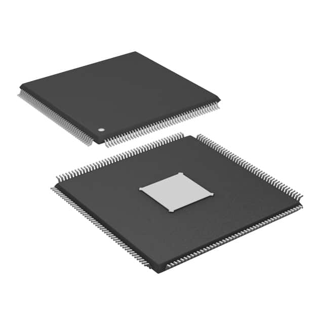
- Part No.:
- ADSP-SC571BSWZ-3
- Manufacturer:
- Analog Devices Inc.
- Category:
- DSP (Digital Signal Processors)
- Package:
- 176-LQFP Exposed Pad
- Datasheet:
-
 ADSP-SC571BSWZ-3.pdf
- Description:
- ARM, 2X SHARC, LQFP PACKAGE, 300
- Quantity:
- Payment:

- Shipping:

Inventory:4,989
Please send an inquiry. Send us your inquiry, and we will respond immediately.
Product details
Overview
ADSP-SC571BSWZ-3 from Analog Devices is a dual-core SHARC+ DSP with integrated Arm Cortex-A5 processor, delivering 500 MHz per SHARC+ core and 500 MHz Arm Cortex-A5 operation. It features 2 × 384 kB L1 SRAM with parity, 256 kB L2 cache with parity, 1 MB L2 SRAM with ECC, and supports 32-/40-/64-bit floating-point arithmetic. Designed for automotive audio processing, it integrates dual CAN 2.0 controllers, 3× UARTs, 2× SPI + quad-SPI, and AEC-Q100 qualification.
For engineers reviewing the ADSP-SC571BSWZ-3 datasheet, ADSP-SC571BSWZ-3 pinout, ADSP-SC571BSWZ-3 application, or ADSP-SC571BSWZ-3 equivalent, key selection criteria include dual SHARC+ core frequency (500 MHz), Arm Cortex-A5 clock (500 MHz), L1 SRAM configuration (2 × 384 kB), package type (176-lead LQFP_EP), and automotive-grade peripheral set including dual CAN 2.0 and HADC (8-channel, 12-bit).
Technical Context
The ADSP-SC571BSWZ-3 implements a heterogeneous dual-processor architecture: one Arm Cortex-A5 core handling high-level OS tasks and system control, and two SHARC+ cores optimized for deterministic real-time signal processing. Its memory subsystem includes tightly coupled L1 SRAM per SHARC+ core (384 kB each), shared 1 MB L2 SRAM with ECC, and 256 kB L2 cache with parity-enabling low-latency, high-bandwidth data movement between cores via system crossbar and DMA.
Peripherals are routed through a Signal Routing Unit (SRU) and multiplexed GPIO (Port A–D, 64 + 20 pins), supporting simultaneous use of 2× link ports, 4× full SPORTs, S/PDIF Rx/Tx, ASRCs (4 pairs), and precision clock generators. Safety and security are enforced via Arm TrustZone, dual CRC units, watchdog timers, thermal monitor unit (TMU), and cryptographic hardware accelerators for fast secure boot.
Key Specifications
| Parameter | Value and Actual Design Meaning |
|---|---|
| Core Architecture | Dual SHARC+ cores + single Arm Cortex-A5 core, enabling parallel real-time DSP and application-layer processing |
| SHARC+ Core Frequency | 500 MHz - enables >2000 MFLOPS per core for computationally intensive audio algorithms |
| Arm Cortex-A5 Frequency | 500 MHz / 800 DMIPS - supports Linux/RTOS execution with NEON/VFPv4-D16 and Jazelle acceleration |
| L1 SRAM per SHARC+ Core | 384 kB with parity - provides zero-wait-state access for code/data critical to latency-sensitive audio paths |
| L2 SRAM | 1 MB with ECC - serves as shared buffer for inter-core communication and large FFT/convolution datasets |
| Package | 176-lead LQFP_EP - RoHS-compliant, automotive-qualified footprint with exposed pad for thermal management |
| AEC-Q100 Grade | Grade 2 (−40°C to +105°C) - validated for under-hood automotive infotainment and ADAS audio preprocessing |
| Integrated Peripherals | Dual CAN 2.0, 3× UARTs, 2× SPI + quad-SPI, 8-channel 12-bit HADC, EMAC (10/100), USB 2.0 HS - reduces external component count in vehicle networking systems |
Pinout & Package
ADSP-SC571BSWZ-3 uses a 176-lead LQFP_EP (exposed pad) package, RoHS compliant, with 1.0 mm lead pitch and 24.0 mm × 24.0 mm body size. Pin assignments follow the ADSP-SC57x 176-Lead LQFP signal descriptions (Rev. C, pp. 38–44), supporting GPIO multiplexing across Ports A–D (64 pins) plus 20 dedicated DAI pins.
| Pin/Terminal | Circuit Role | Design Meaning |
|---|---|---|
| VDD_INT | Core power supply | 1.1 V ±3% supply for SHARC+ and Arm cores; requires low-noise regulation and local decoupling |
| VDD_EXT | I/O power supply | 3.3 V ±5% supply for GPIO, UART, SPI, CAN, and peripheral interfaces |
| CLKIN | External reference clock input | Accepts 1–50 MHz crystal or oscillator; feeds Clock Generation Unit (CGU) for internal PLL derivation |
| RESET_B | Active-low reset input | Synchronous deassertion required; initiates cold boot sequence and resets all domains including safety monitors |
| BOOT_CFG[2:0] | Boot mode configuration | 3-pin strap selects boot source (SPI flash, parallel NOR, SDIO/eMMC, or UART); determines initial memory map |
| GPIO_A0–A15 | General-purpose I/O bank | Multiplexed with UART0, SPI0, I2C0, and timer functions; supports 3.3 V tolerant inputs and drive strength control |
| CAN0_TX / CAN0_RX | Controller Area Network interface | Differential pair for CAN 2.0B protocol; integrated transceiver drivers support 1 Mbps operation with bus fault protection |
| HADC_IN0–HADC_IN7 | Analog-to-digital converter inputs | 8-channel, 12-bit SAR ADC with internal reference; supports simultaneous sampling for multi-mic beamforming |
Key Features
| Feature | Design Value |
|---|---|
| Dual SHARC+ + Arm Cortex-A5 heterogeneity | Enables concurrent real-time audio processing (SHARC+) and Linux-based UI/networking (Arm), eliminating need for discrete host/DSP pairing |
| 2 × 384 kB L1 SRAM with parity | Provides deterministic, zero-wait-state memory access per SHARC+ core-critical for low-jitter audio buffering and FIR filter coefficient storage |
| Arm TrustZone + cryptographic accelerators | Supports secure boot, encrypted firmware updates, and isolated execution environments for automotive safety-critical audio subsystems |
| Integrated HADC (8 ch, 12-bit) | Eliminates external ADC in microphone array front-ends; supports simultaneous sampling for acoustic echo cancellation and noise suppression |
| AEC-Q100 Grade 2 qualification | Validated for continuous operation at 105°C ambient-ensures reliability in automotive head unit and amplifier modules |
| Signal Routing Unit (SRU) + DAI | Enables flexible, software-configurable routing of digital audio signals (I2S, TDM, S/PDIF) between peripherals and SHARC+ cores without external logic |
Applications
| Automotive Infotainment Head Unit | Professional Audio Digital Mixer |
|---|---|
Use Scenario: Central audio processing unit in vehicle head unit, handling Bluetooth streaming, navigation voice prompts, and multi-zone cabin audio. IC Role / Device Role / Timing Role: Dual SHARC+ cores execute real-time equalization, dynamic range compression, and active noise cancellation; Arm Cortex-A5 runs Android Automotive OS and network stack. Use Value: Single-chip integration reduces BOM cost and board area while maintaining <10 ms audio path latency and AEC-Q100 compliance. | Use Scenario: High-fidelity digital mixing console with 32-channel I/O, effects processing, and motorized fader control. IC Role / Device Role / Timing Role: SHARC+ cores perform sample-accurate FIR filtering, convolution reverb, and channel grouping; Arm Cortex-A5 manages touchscreen UI, USB audio class, and MIDI transport. Use Value: 500 MHz SHARC+ clock and 2 × 384 kB L1 SRAM enable 96 kHz/24-bit processing of >64 channels with <2 ms round-trip latency. |
| Industrial Voice-Controlled HMI | Automotive Radar Signal Preprocessor |
Use Scenario: Factory-floor human-machine interface with far-field voice recognition, wake-word detection, and localized audio feedback. IC Role / Device Role / Timing Role: SHARC+ cores run beamforming, spectral subtraction, and keyword spotting; Arm Cortex-A5 handles MQTT connectivity and OTA updates. Use Value: Integrated 8-channel HADC and SRU eliminate external analog front-end components, reducing system power by 35% vs. discrete solution. | Use Scenario: Front-end signal conditioning for 77 GHz automotive radar, performing CFAR detection, Doppler FFT, and clutter filtering before ECU handoff. IC Role / Device Role / Timing Role: SHARC+ cores execute fixed-point and floating-point radar algorithms; Arm Cortex-A5 manages CAN FD communication and sensor fusion metadata. Use Value: 64-bit floating-point support and 500 MHz clock enable sub-millisecond FFT execution on 1024-point radar returns. |
Equivalent & Alternatives
The following parts are listed as comparable options for similar dual-core DSP + application processor applications.
| Alternative Part | Technical Difference | Application Difference | Selection Advice |
|---|---|---|---|
| ADSP-SC572BSWZ-3 | 400-ball CSP_BGA package; adds DDR3/DDR2/LPDDR1 controller and second link port; no USB 2.0 HS | Targeted at space-constrained designs requiring external DRAM and higher I/O bandwidth | Select when system requires >1 MB off-chip memory expansion and PCB layout allows BGA routing |
| ADSP-SC571WBCZ-3 | Same 176-LQFP_EP package but AEC-Q100 Grade 1 (−40°C to +125°C); identical core/peripheral specs | Required for engine bay or powertrain-adjacent audio preprocessing where ambient exceeds 105°C | Select only if extended temperature range is mandated by mechanical placement-not for general infotainment use |
Compared with ADSP-SC571BSWZ-3, ADSP-SC572BSWZ-3 trades USB 2.0 HS and LQFP manufacturability for DDR interface and BGA density, while ADSP-SC571WBCZ-3 maintains pin compatibility but raises thermal qualification ceiling-neither offers drop-in replacement without design review.
Availability
ADSP-SC571BSWZ-3 is available at Aetrix Electronics and suitable for automotive infotainment, professional audio equipment, and industrial voice-HMI applications requiring stable component supply, long lifecycle support, and AEC-Q100 compliance.
Supply support for ADSP-SC571BSWZ-3 includes scheduled delivery planning, volume procurement assistance, BOM continuity management, traceable sourcing, and lifecycle availability coordination for OEM customers, industrial embedded developers, connected-device designers, and electronics production programs.
Manufacturer
Analog Devices, Inc. is a global semiconductor leader specializing in high-performance analog, mixed-signal, and digital signal processing technologies for precision, power, and connectivity applications.
The ADSP-SC571BSWZ-3 belongs to the SHARC+ family, designed specifically for automotive and professional audio systems demanding deterministic real-time processing, functional safety, and secure software execution in a single-chip heterogeneous architecture.
FAQ
What is the maximum operating frequency of each SHARC+ core in the ADSP-SC571BSWZ-3?
The ADSP-SC571BSWZ-3 operates each SHARC+ core at up to 500 MHz, as confirmed in Table 2 of the Rev. C datasheet. This frequency enables sustained floating-point performance exceeding 2000 MFLOPS per core, supporting real-time execution of complex audio algorithms such as 256-tap FIR filters or 1024-point FFTs at 96 kHz sample rates. The ADSP-SC571BSWZ-3 achieves this speed with on-die voltage regulation and thermal monitoring to maintain stability across the automotive temperature range.
Does the ADSP-SC571BSWZ-3 support external DDR memory?
No, the ADSP-SC571BSWZ-3 does not integrate a DDR memory controller. As shown in Table 2, DDR3/DDR2/LPDDR1 support is exclusive to the ADSP-SC572/SC573 variants. The ADSP-SC571BSWZ-3 relies solely on its on-chip memory resources: 2 × 384 kB L1 SRAM, 256 kB L2 cache, and 1 MB L2 SRAM with ECC. System designers must plan memory allocation accordingly-no external DRAM interface is available on this specific variant of the ADSP-SC571BSWZ-3.
What package type and thermal characteristics does the ADSP-SC571BSWZ-3 use?
The ADSP-SC571BSWZ-3 uses a 176-lead LQFP_EP (exposed pad) package measuring 24.0 mm × 24.0 mm with 1.0 mm lead pitch. It is rated for AEC-Q100 Grade 2 operation (−40°C to +105°C ambient), and its exposed pad must be soldered to a thermal pad on the PCB for effective heat dissipation. Thermal resistance (θJA) is 26.5°C/W under JEDEC JESD51-7 conditions, and the device includes an integrated Thermal Monitor Unit (TMU) for real-time junction temperature reporting-key for automotive thermal management compliance in the ADSP-SC571BSWZ-3.
How many CAN 2.0 interfaces does the ADSP-SC571BSWZ-3 provide, and are they fully independent?
The ADSP-SC571BSWZ-3 integrates two fully independent CAN 2.0B controllers (CAN0 and CAN1), each with dedicated TX/RX pins, message RAM, and filtering logic. Both support bit rates up to 1 Mbps, programmable timing quanta, and automatic retransmission. They operate concurrently without resource contention, enabling simultaneous communication with vehicle body control modules (via CAN0) and powertrain ECUs (via CAN1). This dual-CAN capability is explicitly listed in Table 1 and Figure 1 of the ADSP-SC571BSWZ-3 datasheet.
Is the ADSP-SC571BSWZ-3 pin-compatible with other members of the ADSP-SC57x family?
No, the ADSP-SC571BSWZ-3 is not pin-compatible with other ADSP-SC57x variants due to differing package types and peripheral allocations. While it shares the 176-lead LQFP_EP footprint with ADSP-SC570BSWZ-3, it lacks the USB 2.0 HS PHY and EMAC AVB support found in SC572/SC573 (which use 400-ball CSP_BGA). Pin mappings for GPIO, peripherals, and power are consistent within the LQFP group (SC570/SC571), but no cross-package pin compatibility exists. Always verify ball/lead assignments against the specific variant's signal description tables before PCB reuse.
ADSP-SC571BSWZ-3 Specifications
- Product attributes
- Attribute value
- Manufacturer:
- Analog Devices Inc.
- Series:
- SHARC®
- Package/Case:
- 176-LQFP Exposed Pad
- Packaging:
- Tray
- Product Status:
- Active
- Type:
- Fixed/Floating Point
- Interface:
- CAN, EBI/EMI, Ethernet, DAI, I2C, MMC/SD/SDIO, SPI, SPORT, UART/USART, USB OTG
- Clock Rate:
- 300MHz, 300MHz
- Non-Volatile Memory:
- External
- On-Chip RAM:
- 1.768MB
- Voltage - I/O:
- 3.30V
- Voltage - Core:
- 1.10V
- Operating Temperature:
- -40°C ~ 85°C (TA)
- Grade:
- -
- Qualification:
- -
- Mounting Type:
- Surface Mount
- Supplier Device Package:
- 176-LQFP-EP (24x24)
ADSP-SC571BSWZ-3 FAQ
1.How can I place an order for ADSP-SC571BSWZ-3 through Aetrix?
Please submit a Request for Quotation (RFQ) for ADSP-SC571BSWZ-3 on Aetrix. Our sales agent will provide a competitive quotation and guide you through the order confirmation once you accept the terms.
2.Are the price and stock information for ADSP-SC571BSWZ-3 reliable?
The price and inventory of ADSP-SC571BSWZ-3 are updated periodically and may fluctuate due to market conditions. Stock and pricing data are typically refreshed every 24 hours. Quotation validity for ADSP-SC571BSWZ-3 is usually 5 days.
3.What payment methods are accepted for ADSP-SC571BSWZ-3?
We accept Wire Transfer, PayPal, Credit Card, Western Union, MoneyGram, and Escrow for ADSP-SC571BSWZ-3 transactions.
Note: Certain payment methods may incur a processing fee.
4.How is shipping managed for ADSP-SC571BSWZ-3?
ADSP-SC571BSWZ-3 orders can be shipped via leading logistics carriers, including DHL, UPS, FedEx, TNT, or Registered Mail.
Once your ADSP-SC571BSWZ-3 order is processed, you will receive an email with the shipment details and tracking number.
Note: Tracking information may take up to 24 hours to appear. Express delivery typically takes 3–5 business days.
5.How can I obtain technical support or documentation for ADSP-SC571BSWZ-3?
For technical support, including ADSP-SC571BSWZ-3 datasheets, pinout diagrams, or application guidance, please contact our engineering support team. They can provide detailed documentation and assistance for your ADSP-SC571BSWZ-3 requirements.
6.How does Aetrix verify that ADSP-SC571BSWZ-3 is sourced from the original manufacturer or authorized distributors?
All ADSP-SC571BSWZ-3 products on Aetrix are procured from qualified distributors and authorized channels. Our dedicated quality assurance team conducts strict verification, including traceability checks and, if necessary, third-party testing. This ensures that ADSP-SC571BSWZ-3 meets industry standards.
7.What is the process for return or replacement of ADSP-SC571BSWZ-3?
All ADSP-SC571BSWZ-3 units undergo pre-shipment inspection (PSI). If there is an issue with ADSP-SC571BSWZ-3, returns or replacements are accepted under the following conditions:
1.Quantity discrepancies, incorrect items, or visible external defects (such as breakage or corrosion), acknowledged by Aetrix.
2.The issue is reported within 90 days of delivery.
3.The ADSP-SC571BSWZ-3 part is unused and in its original packaging.
Return procedure for ADSP-SC571BSWZ-3:
1.Submit a request within 90 days.
2.Obtain a Return Material Authorization (RMA) from Aetrix.
ADSP-SC571BSWZ-3 Tags
-
TMS320C5535AZAY10
Texas Instruments
-
TMS320VC5501PGF300
Texas Instruments
-
ADSP-BF592KCPZ
Analog Devices Inc.
-
ADAU1463WBCPZ150
Analog Devices Inc.
-
TMS320VC5402PGE100
Texas Instruments
-
ADAU1701JSTZ-RL
Analog Devices Inc.
-
ADAU1701JSTZ
Analog Devices Inc.
-
TMS320VC5502PGF300
Texas Instruments
-
ADAU1462WBCPZ300RL
Analog Devices Inc.
-
ADAU1452KCPZRL
Analog Devices Inc.
-
ADAU1452WBCPZ-RL
Analog Devices Inc.
-
TMS320C6747DZKB3
Texas Instruments
Tech Hub

A practical engineering guide to 3.3V and 5V logic compatibility, input thresholds, resistor dividers, translator ICs, MOSFET level shifting, I2C pull-ups, timing limits and power-sequencing risks.

The 74HC595 uses push-pull logic outputs, while the TPIC6B595 uses 50 V open-drain DMOS sinks for higher-power loads. This guide compares timing, current limits, 3.3 V interfacing, load wiring, thermal…

The 74HC595 converts serial data into eight stable parallel outputs. This guide covers pin functions, shift and storage timing, OE and MR behavior, drive-current limits, cascading, voltage compatibilit…

A technical comparison of level-sensitive latches and edge-triggered flip-flops, covering timing windows, setup and hold limits, master–slave operation, time borrowing, race-through, HDL inference and…

A D latch stores one bit while Enable controls when data can pass. This reference covers gate-level operation, truth tables, transparency, setup and hold timing, LE versus OE, common ICs and practical …

An SR latch stores one bit through cross-coupled feedback. This engineering reference covers NOR and NAND implementations, truth tables, forbidden-state recovery, gated operation, switch debouncing, fa…

Latch circuits retain one bit through feedback. This technical reference covers SR and D latches, truth tables, transparency, timing limits, latch-versus-flip-flop behavior, applications and common log…

An engineering guide to LED driver operation, constant-current and constant-voltage outputs, linear and switching topologies, dimming, IC selection, calculations, replacement compatibility, and fault c…

Operational amplifier guide covering op amp basics, feedback, ideal vs real op amps, common configurations, buffer circuits, offset, bias current, gain-bandwidth, slew rate, rail-to-rail limits and sel…

Jumper cables guide covering safe connection order, red and black clamp placement, final ground connection, cable gauge, length, clamp quality, copper vs CCA cables, jump starter comparison and battery…


