
 My Inquiry
 My Account


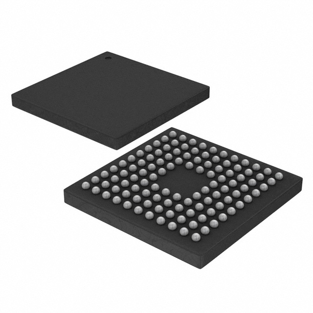
Analog Devices Inc. ADUCM310BBCZ-RL
- Part No.:
- ADUCM310BBCZ-RL
- Manufacturer:
- Analog Devices Inc.
- Category:
- Microcontrollers
- Package:
- 112-TFBGA, CSPBGA
- Datasheet:
-
 ADUCM310BBCZ-RL.pdf
- Description:
- IC MCU 32B 256KB FLASH 112CSPBGA
- Quantity:
- Payment:

- Shipping:

Inventory:2,240
Please send an inquiry. Send us your inquiry, and we will respond immediately.
Product details
Overview
ADUCM310BBCZ-RL from Analog Devices is a precision analog microcontroller engineered for closed-loop diagnostic control in tunable laser optical modules. It integrates an ARM Cortex-M3 core, 22-channel 14-bit 800 kSPS SAR ADC, six 14-bit IDACs (including −3.0 V SOA current sink), eight 12-bit VDACs with dual-polarity outputs, and 256 kB Flash/32 kB SRAM - all in a 6 mm × 6 mm 112-ball CSP_BGA package rated for −40°C to +85°C.
For engineers reviewing the ADUCM310BBCZ-RL datasheet, ADUCM310BBCZ-RL pinout, ADUCM310BBCZ-RL application, or ADUCM310BBCZ-RL equivalent, this device serves as a system-on-die solution for high-accuracy optical power stabilization, wavelength tuning feedback, and real-time laser diode bias control in DWDM transceivers and tunable XFP/SFP+ modules.
Technical Context
The ADUCM310BBCZ-RL employs a three-die stacked architecture: bottom die hosts precision analog circuitry (ADC, VDACs, IDACs, 2.5 V reference); middle die contains the 80 MHz ARM Cortex-M3 processor, memory, and digital peripherals; top die implements high-voltage ±5 V VDAC outputs and −3.0 V SOA current sink capability. This partitioning enables simultaneous high-accuracy analog measurement, fast digital control, and robust optical driver interfacing.
Its analog subsystem features fully differential/single-ended ADC inputs (0 V to 2.5 V range), buffered 2.5 V reference outputs (±5 mV accuracy, 30 ppm/°C drift), and IDACs with programmable compliance (e.g., IDAC3: 0–250 mA source / −80 mA sink, −3.7 V to −3.0 V sink range). All DACs drive specified capacitive loads (up to 10 nF) and support calibrated output ranges including −5 V to 0 V (VDAC2/VDAC3) and 0 V to 5 V (VDAC6/VDAC7).
Key Specifications
| Parameter | Value and Actual Design Meaning |
|---|---|
| Core Processor | ARM Cortex-M3, 80 MHz max clock, 100 DMIPS performance for real-time optical control loops |
| ADC Resolution & Speed | 14-bit SAR, 800 kSPS - supports high-fidelity monitoring of photodiode currents and thermistor voltages |
| IDAC Output Range | IDAC3: 0–250 mA source / −80 mA sink with −3.0 V fast shutdown - directly drives semiconductor optical amplifiers |
| VDAC Output Ranges | VDAC2/VDAC3: −5 V to 0 V (500 Ω load); VDAC6/VDAC7: 0 V to 5 V (100 Ω load) - enables dual-rail laser bias control |
| On-Chip Reference | 2.5 V bandgap reference, ±5 mV accuracy at 25°C, 30 ppm/°C drift - ensures stable ADC/IDAC/VDAC scaling across temperature |
| Memory | 256 kB Flash/EE (10,000 write cycles), 32 kB SRAM - sufficient for firmware, calibration tables, and real-time waveform buffers |
| Package & Temp | 6 mm × 6 mm, 112-ball CSP_BGA; fully specified from −40°C to +85°C ambient - suitable for pluggable optical module environments |
Pinout & Package
ADUCM310BBCZ-RL is housed in a 6 mm × 6 mm, 112-ball CSP_BGA package with 0.4 mm ball pitch. Pin functions are defined per the official Analog Devices ADuCM310 Rev. C datasheet (Pages 18–21), supporting dedicated analog inputs (AIN0–AIN9), IDAC/VDAC terminals (e.g., IDAC0–IDAC5, VDAC0–VDAC7), reference outputs (BUF_VREF2.5A/B), and digital interfaces (SWDIO, SWCLK, UART, I²C, SPI).
| Pin/Terminal | Circuit Role | Design Meaning |
|---|---|---|
| AIN0–AIN9 | Analog Input Channels | 10 external single-ended/differential ADC inputs; 0 V–2.5 V range supports photodiode TIA outputs and thermistor dividers |
| IDAC0–IDAC5 | Current DAC Outputs | 14-bit IDACs with programmable full-scale (20–250 mA); IDAC3 provides −3.0 V sink for SOA fast turn-off |
| VDAC0–VDAC7 | Voltage DAC Outputs | 12-bit buffered VDACs; VDAC2/VDAC3 support −5 V to 0 V for laser cathode bias; VDAC6/VDAC7 support 0–5 V for anode control |
| BUF_VREF2.5A/B | Buffered Reference Outputs | 2× 2.5 V outputs, ±5 mV accuracy, 1.2 mA drive - usable as external ADC reference or sensor excitation |
| SWDIO/SWCLK | Serial Wire Debug Interface | 2-pin ARM SW-DP interface for non-intrusive firmware download, real-time debugging, and in-circuit reprogramming |
Key Features
| Feature | Design Value |
|---|---|
| Three-die stacked architecture | Enables co-location of high-voltage VDACs (top die), precision analog (bottom die), and digital logic (middle die) without cross-coupling |
| SOA IDAC with −3.0 V sink | IDAC3 delivers fast optical shutdown (<1 μs switching) by pulling SOA anode below ground - critical for laser safety compliance |
| Dual-polarity VDAC outputs | VDAC2/VDAC3 (−5 V to 0 V) and VDAC0/VDAC1 (0 V to 3 V) allow independent control of laser cathode/anode bias in tunable EMLs |
| On-chip 2.5 V reference with low drift | 30 ppm/°C tempco and ±5 mV initial accuracy ensure consistent ADC/IDAC/VDAC scaling across industrial temperature range |
| Integrated 32-element PLA | Programmable logic array enables hardware-accelerated signal conditioning (e.g., averaging, threshold detection) offloading CPU |
Applications
| Tunable Laser Diode Control | Optical Power Stabilization |
|---|---|
Use Scenario: Real-time adjustment of laser bias current and temperature setpoint in C-band tunable lasers for DWDM systems. IC Role / Device Role / Timing Role: ADUCM310BBCZ-RL acts as the primary closed-loop controller, sampling photodiode feedback and thermistor voltage via its 14-bit ADC, then driving IDACs and VDACs to maintain target wavelength and output power. Use Value: 800 kSPS ADC sampling and <1 μs IDAC3 sink switching enable sub-millisecond response to optical power transients, meeting GR-468 reliability requirements. |
Use Scenario: Maintaining constant optical output power in SFP28 tunable transceivers despite aging and temperature drift. IC Role / Device Role / Timing Role: ADUCM310BBCZ-RL executes PID algorithms using internal temperature sensor and ADC-measured monitor photodiode current, updating 12-bit VDACs every 100 μs. Use Value: Integrated 2.5 V reference and matched VDAC/IDAC linearity (±1 LSB INL) reduce calibration overhead and improve long-term power stability to ±0.1 dB. |
| Laser Safety Interlock System | Multi-Channel Optical Module Diagnostics |
Use Scenario: Enforcing Class 1 laser safety by forcing immediate optical shutdown upon fault detection (e.g., TEC failure, overtemperature). IC Role / Device Role / Timing Role: ADUCM310BBCZ-RL monitors die temperature and supply rails; triggers IDAC3's −3.0 V sink within 1 μs to disable SOA when thresholds are exceeded. Use Value: Hardware-fast shutdown path bypasses software latency - meets IEC 60825-1 Class 1 interlock timing requirements without external comparators. |
Use Scenario: Comprehensive health monitoring of tunable XFP modules, including laser bias, TEC voltage, case temperature, and supply rail integrity. IC Role / Device Role / Timing Role: ADUCM310BBCZ-RL aggregates 22 analog channels (10 external + 6 IDAC monitors + 3 power rails + temp sensor + ref monitors) into a unified diagnostic dataset. Use Value: Single-chip integration eliminates external mux/ADC, reducing BOM count by 7 components and improving channel-to-channel crosstalk (<−95 dB) for accurate multi-parameter correlation. |
Equivalent & Alternatives
The following parts are listed as comparable options for similar optical control microcontroller applications.
| Alternative Part | Technical Difference | Application Difference | Selection Advice |
|---|---|---|---|
| ADUCM360BCPZ-RL7 | Single-die 18-bit Σ-Δ ADC, no integrated VDACs or SOA sink; 64-pin LFCSP; lacks −5 V/−3 V high-voltage outputs | Suitable for high-resolution sensor readout only - cannot replace ADUCM310BBCZ-RL in laser bias control or fast shutdown roles | Select only if application requires ultra-low-noise analog sensing without active optical actuation. |
| MAX32660GWE+T | ARM Cortex-M4F, 16-bit ADC, no IDACs, no negative VDACs; 42-pin WLP; no SOA sink or −5 V capability | Targeted at wearable biosensors - lacks the high-current IDACs, dual-polarity VDACs, and optical-specific safety features | Consider only for cost-sensitive, low-complexity optical monitoring where active laser control is handled externally. |
Compared with ADUCM310BBCZ-RL, both alternatives lack the integrated −3.0 V SOA sink, dual-polarity VDACs, and three-die architecture required for autonomous tunable laser control - making them unsuitable as functional replacements in optical module designs requiring closed-loop bias, wavelength tuning, and safety interlocks.
Availability
ADUCM310BBCZ-RL is available at Aetrix Electronics and suitable for tunable laser modules, optical transceivers, and DWDM subsystems requiring stable component supply, long-lifecycle support, and guaranteed traceability for telecom-grade production.
Supply support for ADUCM310BBCZ-RL includes scheduled delivery planning, volume procurement assistance, BOM continuity management, traceable sourcing, and lifecycle availability coordination for OEM customers, industrial embedded developers, connected-device designers, and electronics production programs.
Manufacturer
Analog Devices, Inc. is a global leader in high-performance analog, mixed-signal, and digital signal processing semiconductors, headquartered in Norwood, MA, with design centers worldwide.
The ADUCM310BBCZ-RL belongs to Analog Devices' precision analog microcontroller product line, specifically architected for optical module manufacturers needing integrated, high-accuracy analog control, real-time processing, and laser safety compliance in compact pluggable form factors.
FAQ
What is the primary application domain for the ADUCM310BBCZ-RL?
The ADUCM310BBCZ-RL is purpose-built for tunable laser optical modules used in DWDM, coherent, and pluggable transceivers (e.g., XFP, SFP+, QSFP). Its integrated SOA IDAC with −3.0 V sink, dual-polarity VDACs, and 14-bit ADC enable closed-loop wavelength tuning, optical power stabilization, and laser safety interlocks - all within a single 6 mm × 6 mm CSP_BGA package. ADUCM310BBCZ-RL replaces discrete analog + MCU solutions in space-constrained optical assemblies.
Does the ADUCM310BBCZ-RL support external crystal oscillators?
Yes, the ADUCM310BBCZ-RL supports an external 16 MHz crystal via XCLKI/XCLKO pins, which can be used as the PLL input to generate the 80 MHz system clock. It also includes an internal trimmed 16 MHz oscillator and a 32.768 kHz low-power oscillator for wake-up timers. The external crystal option improves frequency stability for time-critical optical control loops where internal oscillator drift (±3%) is insufficient. ADUCM310BBCZ-RL's clocking flexibility allows optimization between accuracy and power consumption.
What are the voltage compliance limits for the IDAC outputs on the ADUCM310BBCZ-RL?
IDAC0, IDAC1, and IDAC2 have a compliance range of 0.4 V to (PVDD − 200 mV); IDAC4 and IDAC5: 0.4 V to (PVDD − 200 mV); IDAC3: 0.5 V to (PVDD − 450 mV) for sourcing, and −3.7 V to −3.0 V for sinking. These limits ensure safe operation with common optical components: IDAC3's −3.0 V sink directly interfaces with SOA anodes requiring fast turn-off, while IDAC2's 200 mA sourcing drives TEC elements. ADUCM310BBCZ-RL's compliance ranges are validated across −40°C to +85°C.
How does the ADUCM310BBCZ-RL handle reference voltage accuracy and drift?
The ADUCM310BBCZ-RL features an on-chip 2.5 V bandgap reference with ±5 mV initial accuracy at 25°C and a maximum temperature coefficient of 30 ppm/°C. Two buffered 2.5 V outputs (BUF_VREF2.5A/B) deliver up to 1.2 mA each and require 100 nF decoupling. This reference is used internally by the ADC, IDACs, and VDACs - ensuring correlated scaling and minimizing gain error drift. ADUCM310BBCZ-RL's reference design eliminates need for external precision references in optical control loops.
Is the ADUCM310BBCZ-RL pin-compatible with other ADuCM3xx devices?
No, the ADUCM310BBCZ-RL is not pin-compatible with other ADuCM3xx family members due to its unique 112-ball CSP_BGA package and optical-specific peripheral allocation (e.g., dedicated SOA sink pins, dual-polarity VDAC supplies). While it shares the ARM Cortex-M3 core and some peripheral IP with ADuCM360/361, the pinout, power domains (AVNEG, VDACVDD, PVDD), and analog I/O mapping are distinct. Migration requires PCB redesign. ADUCM310BBCZ-RL's pin configuration is optimized exclusively for optical module integration.
ADUCM310BBCZ-RL Specifications
- Product attributes
- Attribute value
- Manufacturer:
- Analog Devices Inc.
- Package/Case:
- 112-TFBGA, CSPBGA
- Series:
- ADuCM
- Packaging:
- Tape & Reel (TR)
- Product Status:
- Active
- Programmable:
- Not Verified
- Core Processor:
- ARM® Cortex®-M3
- Core Size:
- 32-Bit Single-Core
- Speed:
- 80MHz
- Connectivity:
- I2C, SPI, UART/USART
- Peripherals:
- DMA, POR, PWM, WDT
- Number of I/O:
- 28
- Program Memory Size:
- 256KB (128K x 8 x 2)
- Program Memory Type:
- FLASH
- EEPROM Size:
- -
- RAM Size:
- 32K x 8
- Voltage - Supply (Vcc/Vdd):
- 2.9V ~ 3.6V
- Data Converters:
- A/D 22x14b; D/A 8x12b
- Oscillator Type:
- Internal
- Operating Temperature:
- -10°C ~ 85°C (TA)
- Grade:
- -
- Qualification:
- -
- Mounting Type:
- Surface Mount
- Supplier Device Package:
ADUCM310BBCZ-RL FAQ
1.How can I place an order for ADUCM310BBCZ-RL through Aetrix?
Please submit a Request for Quotation (RFQ) for ADUCM310BBCZ-RL on Aetrix. Our sales agent will provide a competitive quotation and guide you through the order confirmation once you accept the terms.
2.Are the price and stock information for ADUCM310BBCZ-RL reliable?
The price and inventory of ADUCM310BBCZ-RL are updated periodically and may fluctuate due to market conditions. Stock and pricing data are typically refreshed every 24 hours. Quotation validity for ADUCM310BBCZ-RL is usually 5 days.
3.What payment methods are accepted for ADUCM310BBCZ-RL?
We accept Wire Transfer, PayPal, Credit Card, Western Union, MoneyGram, and Escrow for ADUCM310BBCZ-RL transactions.
Note: Certain payment methods may incur a processing fee.
4.How is shipping managed for ADUCM310BBCZ-RL?
ADUCM310BBCZ-RL orders can be shipped via leading logistics carriers, including DHL, UPS, FedEx, TNT, or Registered Mail.
Once your ADUCM310BBCZ-RL order is processed, you will receive an email with the shipment details and tracking number.
Note: Tracking information may take up to 24 hours to appear. Express delivery typically takes 3–5 business days.
5.How can I obtain technical support or documentation for ADUCM310BBCZ-RL?
For technical support, including ADUCM310BBCZ-RL datasheets, pinout diagrams, or application guidance, please contact our engineering support team. They can provide detailed documentation and assistance for your ADUCM310BBCZ-RL requirements.
6.How does Aetrix verify that ADUCM310BBCZ-RL is sourced from the original manufacturer or authorized distributors?
All ADUCM310BBCZ-RL products on Aetrix are procured from qualified distributors and authorized channels. Our dedicated quality assurance team conducts strict verification, including traceability checks and, if necessary, third-party testing. This ensures that ADUCM310BBCZ-RL meets industry standards.
7.What is the process for return or replacement of ADUCM310BBCZ-RL?
All ADUCM310BBCZ-RL units undergo pre-shipment inspection (PSI). If there is an issue with ADUCM310BBCZ-RL, returns or replacements are accepted under the following conditions:
1.Quantity discrepancies, incorrect items, or visible external defects (such as breakage or corrosion), acknowledged by Aetrix.
2.The issue is reported within 90 days of delivery.
3.The ADUCM310BBCZ-RL part is unused and in its original packaging.
Return procedure for ADUCM310BBCZ-RL:
1.Submit a request within 90 days.
2.Obtain a Return Material Authorization (RMA) from Aetrix.
ADUCM310BBCZ-RL Tags

-
ATTINY4-TSHR
Microchip Technology
-
ATTINY10-TSHR
Microchip Technology
-
ATTINY10-TS8R
Microchip Technology

-
ATTINY202-SSNR
Microchip Technology
-
ATTINY202-SSFR
Microchip Technology
-
ATTINY402-SSNR
Microchip Technology

-
PIC16F15213T-I/MF
Microchip Technology
-
PIC16F15213-E/MF
Microchip Technology

-
PIC10F200T-I/OT
Microchip Technology
-
ATTINY412-SSNR
Microchip Technology
-
PIC10F202T-I/OT
Microchip Technology

-
ATTINY404-SSNR
Microchip Technology
Tech Hub

A practical engineering guide to 3.3V and 5V logic compatibility, input thresholds, resistor dividers, translator ICs, MOSFET level shifting, I2C pull-ups, timing limits and power-sequencing risks.

The 74HC595 uses push-pull logic outputs, while the TPIC6B595 uses 50 V open-drain DMOS sinks for higher-power loads. This guide compares timing, current limits, 3.3 V interfacing, load wiring, thermal…

The 74HC595 converts serial data into eight stable parallel outputs. This guide covers pin functions, shift and storage timing, OE and MR behavior, drive-current limits, cascading, voltage compatibilit…

A technical comparison of level-sensitive latches and edge-triggered flip-flops, covering timing windows, setup and hold limits, master–slave operation, time borrowing, race-through, HDL inference and…

A D latch stores one bit while Enable controls when data can pass. This reference covers gate-level operation, truth tables, transparency, setup and hold timing, LE versus OE, common ICs and practical …

An SR latch stores one bit through cross-coupled feedback. This engineering reference covers NOR and NAND implementations, truth tables, forbidden-state recovery, gated operation, switch debouncing, fa…

Latch circuits retain one bit through feedback. This technical reference covers SR and D latches, truth tables, transparency, timing limits, latch-versus-flip-flop behavior, applications and common log…

An engineering guide to LED driver operation, constant-current and constant-voltage outputs, linear and switching topologies, dimming, IC selection, calculations, replacement compatibility, and fault c…

Operational amplifier guide covering op amp basics, feedback, ideal vs real op amps, common configurations, buffer circuits, offset, bias current, gain-bandwidth, slew rate, rail-to-rail limits and sel…

Jumper cables guide covering safe connection order, red and black clamp placement, final ground connection, cable gauge, length, clamp quality, copper vs CCA cables, jump starter comparison and battery…


