
 My Inquiry
 My Account


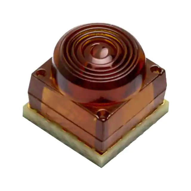
Broadcom Limited AFBR-FS13B25
- Part No.:
- AFBR-FS13B25
- Manufacturer:
- Broadcom Limited
- Category:
- Fiber Optic Transceiver Modules
- Package:
- Datasheet:
-
 AFBR-FS13B25.pdf
- Description:
- TRANSCEIVER 1,25GBPS 25MM
- Quantity:
- Payment:

- Shipping:

Inventory:184
Please send an inquiry. Send us your inquiry, and we will respond immediately.
Product details
Overview
AFBR-FS13B25 from Broadcom is a free-space optical transceiver enabling full-duplex bidirectional wireless data transmission at rates from 125 Mb/s to 1.25 Gb/s over distances of 20–100 mm. It integrates an 850-nm VCSEL transmitter and high-speed PIN photodiode receiver, operates from a single 3.3 V supply, and maintains full functionality across 360° rotation-ideal for rotary optical data feedthroughs in industrial encoders and board-to-board interconnects.
For engineers reviewing the AFBR-FS13B25 datasheet, pinout, applications, or equivalent options, key selection considerations include its differential Tx/Rx I/O, signal detect (SD) and monitor current (Imon) outputs, laser Class 1 safety compliance, SMT-compatible 5.25 × 5.25 × 4.83 mm package, and immunity to RF fields up to 10 V/m (80 MHz–6 GHz).
Technical Context
The AFBR-FS13B25 implements independent transmitter and receiver signal chains: the Tx IC converts LVDS differential inputs (0.2–1.4 Vp-p) into analog drive current for an 850-nm VCSEL (λc = 830–870 nm), while the Rx IC integrates a transimpedance amplifier and limiting amplifier to deliver differential logic outputs (0.18–0.33 Vp) with <200 ps rise/fall times.
It supports active control via Tx EN and Rx EN pins (active-HIGH), provides real-time optical link monitoring via Imon (mirrored PD current) and SD (logic HIGH when Imon ≥ 3 µA), and uses dedicated decoupling pins (FILT, VDD15) to stabilize Tx and Rx power domains-enabling robust operation in noisy industrial environments without enclosure shielding.
Key Specifications
| Parameter | Value and Actual Design Meaning |
|---|---|
| Data rate | 125 Mb/s to 1.25 Gb/s - supports 8b10b encoded links with BER ≤ 2.5×10⁻¹⁰ at perfect alignment |
| Link distance | 20 mm to 100 mm - lens-to-lens spacing; lateral misalignment tolerance ≤1.0 mm at 30 mm |
| Optical wavelength | 850 nm VCSEL + PIN PD - centered at 850 nm (±20 nm), FWHM ≤ 0.85 nm |
| Supply voltage | 3.3 V ±3% for both Tx and Rx - dual regulated rails (VDDTx/VDDRx) with separate decoupling |
| Operating temperature | –40°C to +85°C - guaranteed electrical/optical performance across full range |
| Laser safety | IEC/EN 60825-1 Class 1 - inherently safe; no user-accessible hazardous radiation |
| ESD rating | HBM ±1 kV - meets JEDEC JS-001-2012 for handling in standard assembly lines |
Pinout & Package
AFBR-FS13B25 uses a compact 28-pin surface-mount package measuring 5.25 mm × 5.25 mm × 4.83 mm (L × W × H), with exposed thermal pad on bottom side connected to GND. Pin 1 is located at upper-left corner (top view); all GND pins (1, 2, 5, 7, 15, 17, 20, 21, 22, 24, 28) provide low-inductance return paths.
| Pin/Terminal | Circuit Role | Design Meaning |
|---|---|---|
| 1, 2, 5, 7, 15, 17, 20, 21, 22, 24, 28 | GND | Common ground reference for Tx, Rx, and power domains; critical for EMI suppression and signal integrity |
| 3, 4 | Rx+, Rx− | Differential logic output - 100 Ω terminated, AC-coupled; VOCM = 180–330 mV, VDout = 0.18–0.33 Vp |
| 18, 19 | Tx−, Tx+ | Differential LVDS input - self-biased, 90–110 Ω impedance, 0.2–1.4 Vp-p swing |
| 6 | VDDRx | Receiver power supply - must be decoupled with 100 nF capacitor near pin |
| 24 | VDDTx | Transmitter power supply - filtered via FILT pin (pin 23) and local 100 nF cap |
| 9 | SD | Signal Detect output - open-drain logic HIGH (≥1.1 V) when Imon ≥ 3 µA; indicates valid optical link |
| 10 | Imon | Monitor current output - proportional to received optical power; used for link margin assessment and fault detection |
| 12 | Tx EN | Transmitter enable - active-HIGH; disables VCSEL driver and reduces Tx ICC to <100 µA when LOW |
| 25 | Rx EN | Receiver enable - active-HIGH; powers down Rx IC and sets SD LOW when disabled |
Key Features
| Feature | Design Value |
|---|---|
| Full-duplex bidirectional operation | Simultaneous Tx and Rx at up to 1.25 Gb/s without crosstalk-enables real-time feedback loops in motion control systems |
| 360° rotational symmetry | No alignment sensitivity around optical axis-eliminates precision mounting fixtures in rotary joints and slip rings |
| Differential I/O with integrated biasing | LVDS-compatible Tx input and Rx output require no external termination or bias networks-reduces BOM count and PCB area |
| Integrated link health monitoring | SD and Imon pins provide real-time optical power feedback-supports predictive maintenance and automatic link retraining |
| Laser Class 1 compliance | No safety interlocks or enclosure required-simplifies system certification for medical and industrial equipment |
Applications
| Rotary Optical Data Feedthrough | Board-to-Board Wireless Interconnect |
|---|---|
Use Scenario: Transmitting encoder position data across rotating shafts in CNC machines or robotic joints where slip rings introduce noise and wear. IC Role / Device Role / Timing Role: Full-duplex optical transceiver providing galvanically isolated, jitter-controlled serial data link with <200 ps edge timing. Use Value: Eliminates mechanical wear and EMI from slip rings; maintains sub-micron position accuracy over >10⁹ rotations. | Use Scenario: Replacing flex cables between stacked PCBs in space-constrained test equipment or modular instrumentation. IC Role / Device Role / Timing Role: High-speed wireless bridge delivering deterministic latency and bit-error-free 1.25 Gb/s links without connector mating cycles. Use Value: Enables hot-swappable modules and field-replaceable units without solder rework or cable fatigue failure. |
| Through-Window Optical Communication | Industrial Sensor Interface |
Use Scenario: Transmitting sensor telemetry through sealed glass windows in hazardous-area process analyzers or cleanroom monitors. IC Role / Device Role / Timing Role: Free-space optical transceiver operating across transparent barriers with no RF emissions or metallic penetration. Use Value: Preserves IP66/NEMA 4X enclosure integrity while supporting real-time diagnostics and firmware updates. | Use Scenario: Connecting distributed pressure/temperature sensors to a central controller in explosive atmospheres where wired connections risk ignition. IC Role / Device Role / Timing Role: Intrinsically safe optical interface with Class 1 laser output and <100 mW total power dissipation. Use Value: Meets IEC 60079-28 optical radiation limits; enables certified ATEX/IECEx Zone 1 deployments without barrier devices. |
Equivalent & Alternatives
The following parts are listed as comparable options for similar optical wireless transceiver applications.
| Alternative Part | Technical Difference | Application Difference | Selection Advice |
|---|---|---|---|
| Avago AFBR-13B25Z | Same die, identical pinout and optical specs; differs only in tape-and-reel packaging and datecode marking per Broadcom internal revision control | No functional difference; qualified for same automotive-grade reflow profiles and humidity exposure levels | Select AFBR-13B25Z only if legacy BOM references that part number-AFBR-FS13B25 is the current production variant |
| Vishay TFDU4301 | IR LED + phototransistor pair; 4 Mbps max data rate; no differential I/O or SD/Imon monitoring; requires external biasing | Targeted at low-cost remote control and proximity sensing-not suitable for >100 Mbps or closed-loop feedback systems | Choose TFDU4301 only for cost-sensitive, low-speed (<10 Mbps), non-critical applications where link margin monitoring is unnecessary |
Compared with AFBR-13B25Z (identical function, packaging variant) and TFDU4301 (lower-speed, discrete-component architecture), the AFBR-FS13B25 delivers 312× higher data throughput, integrated diagnostics, and guaranteed Class 1 safety-making it the sole option for industrial motion control and certified hazardous-area wireless interfaces.
Availability
AFBR-FS13B25 is available at Aetrix Electronics and suitable for rotary optical data feedthroughs, board-to-board wireless interconnects, and through-window optical communication systems requiring stable component supply, long-term lifecycle support, and RoHS-compliant SMT assembly.
Supply support for AFBR-FS13B25 includes scheduled delivery planning, volume procurement assistance, BOM continuity management, traceable sourcing, and lifecycle availability coordination for OEM customers, industrial embedded developers, connected-device designers, and electronics production programs.
Manufacturer
Broadcom Inc. is a global semiconductor leader designing connectivity, networking, and optical components for enterprise, industrial, and communications infrastructure.
The AFBR-FS13B25 belongs to Broadcom's Free-Space Optical Transceiver product line, engineered specifically for high-reliability, alignment-tolerant wireless data transfer in motion-critical and safety-certified systems.
FAQ
What is the maximum supported data rate and corresponding bit error rate for AFBR-FS13B25?
The AFBR-FS13B25 supports up to 1.25 Gb/s with a guaranteed bit error rate of ≤2.5×10⁻¹⁰ under ideal alignment conditions using 8b10b encoding. At this rate, total jitter at the receiver is ≤0.35 UI. Performance degrades predictably with lateral misalignment or tilt-lateral tolerance is ≤1.0 mm at 30 mm link distance. The AFBR-FS13B25 datasheet specifies these values under recommended operating conditions (3.3 V, 25°C).
Does AFBR-FS13B25 require external biasing or termination resistors for its differential I/O?
No, the AFBR-FS13B25 incorporates self-biasing differential inputs and outputs. Its Tx input accepts LVDS signals (0.2–1.4 Vp-p) without external biasing, and its Rx output drives a 100 Ω differential load with common-mode voltage of 180–330 mV. External 100 nF decoupling capacitors are required at VDDRx and VDDTx, but no pull-ups, pull-downs, or termination resistors are needed on Tx+/Tx− or Rx+/Rx− lines.
How is optical link health monitored using AFBR-FS13B25?
The AFBR-FS13B25 provides two dedicated monitoring outputs: Imon (pin 10) delivers a current proportional to received optical power, enabling quantitative link margin assessment; SD (pin 9) outputs a logic HIGH (≥1.1 V) when Imon ≥ 3 µA-indicating a valid optical signal. These signals allow real-time diagnostics, automatic retraining, and predictive maintenance without external photodetectors or ADCs.
What is the significance of the FILT and VDD15 pins on AFBR-FS13B25?
FILT (pin 23) is a dedicated Tx power supply decoupling node requiring a local 100 nF capacitor to suppress high-frequency switching noise from the VCSEL driver. VDD15 (pin 27) supplies an internal 1.5 V LDO; it must be left open or connected to a 1 nF capacitor (recommended) to stabilize the internal bias network. Both pins are essential for achieving specified jitter and EMI performance-omitting either degrades signal integrity and increases BER.
Is AFBR-FS13B25 compatible with lead-free reflow processes?
Yes, AFBR-FS13B25 is qualified for lead-free reflow with a peak temperature of +245°C for ≤10 seconds (MSL 5a). Its recommended profile includes preheat, soak, and reflow stages aligned to JEDEC J-STD-020. Thermal overstress beyond these limits may damage the VCSEL or lens bond. The device's SMT solderability has been validated per IPC-J-STD-002 and IPC-J-STD-003 standards.
AFBR-FS13B25 Specifications
- Product attributes
- Attribute value
- Manufacturer:
- Broadcom Limited
- Series:
- -
- Packaging:
- Tray
- Product Status:
- Active
- Data Rate:
- 1.25Gbps
- Wavelength:
- 850nm
- Applications:
- Optical
- Voltage - Supply:
- 3.13V ~ 3.47V
- Connector Type:
- -
- Mounting Type:
- Surface Mount
AFBR-FS13B25 FAQ
1.How can I place an order for AFBR-FS13B25 through Aetrix?
Please submit a Request for Quotation (RFQ) for AFBR-FS13B25 on Aetrix. Our sales agent will provide a competitive quotation and guide you through the order confirmation once you accept the terms.
2.Are the price and stock information for AFBR-FS13B25 reliable?
The price and inventory of AFBR-FS13B25 are updated periodically and may fluctuate due to market conditions. Stock and pricing data are typically refreshed every 24 hours. Quotation validity for AFBR-FS13B25 is usually 5 days.
3.What payment methods are accepted for AFBR-FS13B25?
We accept Wire Transfer, PayPal, Credit Card, Western Union, MoneyGram, and Escrow for AFBR-FS13B25 transactions.
Note: Certain payment methods may incur a processing fee.
4.How is shipping managed for AFBR-FS13B25?
AFBR-FS13B25 orders can be shipped via leading logistics carriers, including DHL, UPS, FedEx, TNT, or Registered Mail.
Once your AFBR-FS13B25 order is processed, you will receive an email with the shipment details and tracking number.
Note: Tracking information may take up to 24 hours to appear. Express delivery typically takes 3–5 business days.
5.How can I obtain technical support or documentation for AFBR-FS13B25?
For technical support, including AFBR-FS13B25 datasheets, pinout diagrams, or application guidance, please contact our engineering support team. They can provide detailed documentation and assistance for your AFBR-FS13B25 requirements.
6.How does Aetrix verify that AFBR-FS13B25 is sourced from the original manufacturer or authorized distributors?
All AFBR-FS13B25 products on Aetrix are procured from qualified distributors and authorized channels. Our dedicated quality assurance team conducts strict verification, including traceability checks and, if necessary, third-party testing. This ensures that AFBR-FS13B25 meets industry standards.
7.What is the process for return or replacement of AFBR-FS13B25?
All AFBR-FS13B25 units undergo pre-shipment inspection (PSI). If there is an issue with AFBR-FS13B25, returns or replacements are accepted under the following conditions:
1.Quantity discrepancies, incorrect items, or visible external defects (such as breakage or corrosion), acknowledged by Aetrix.
2.The issue is reported within 90 days of delivery.
3.The AFBR-FS13B25 part is unused and in its original packaging.
Return procedure for AFBR-FS13B25:
1.Submit a request within 90 days.
2.Obtain a Return Material Authorization (RMA) from Aetrix.
AFBR-FS13B25 Tags
-
AFBR-5972EZ
Broadcom Limited
-
AFBR-5972BZ
Broadcom Limited
-
FTLF8519P3BNL
Coherent
-
AFBR-5803Z
Broadcom Limited
-
AFBR-5803TZ
Broadcom Limited
-
FTLF8519P3BTL
Coherent
-
AFBR-5803ATZ
Broadcom Limited
-
AFBR-5803ATQZ
Broadcom Limited
-
FTLX8574D3BCV
Coherent
-
FTLF8526P3BNL
Coherent
-
FTLF8519F2GCL
Coherent
-
FTLF1318P3BTL
Coherent
Tech Hub

Counterfeit components can hide behind convincing markings and passing basic function tests. This engineering reference covers source traceability, external inspection, X-ray, XRF, electrical testing, …

A practical engineering and sourcing framework covering lifecycle verification, lifetime-buy calculations, replacement qualification, supplier checks and counterfeit-risk controls.

TTL and CMOS logic families differ in thresholds, loading, output drive, power and timing. This engineering guide compares 74HC and 74HCT, calculates noise margins and checks 3.3 V/5 V compatibility.

A practical engineering guide to 3.3V and 5V logic compatibility, input thresholds, resistor dividers, translator ICs, MOSFET level shifting, I2C pull-ups, timing limits and power-sequencing risks.

The 74HC595 uses push-pull logic outputs, while the TPIC6B595 uses 50 V open-drain DMOS sinks for higher-power loads. This guide compares timing, current limits, 3.3 V interfacing, load wiring, thermal…

The 74HC595 converts serial data into eight stable parallel outputs. This guide covers pin functions, shift and storage timing, OE and MR behavior, drive-current limits, cascading, voltage compatibilit…

A technical comparison of level-sensitive latches and edge-triggered flip-flops, covering timing windows, setup and hold limits, master–slave operation, time borrowing, race-through, HDL inference and…

A D latch stores one bit while Enable controls when data can pass. This reference covers gate-level operation, truth tables, transparency, setup and hold timing, LE versus OE, common ICs and practical …

An SR latch stores one bit through cross-coupled feedback. This engineering reference covers NOR and NAND implementations, truth tables, forbidden-state recovery, gated operation, switch debouncing, fa…

Latch circuits retain one bit through feedback. This technical reference covers SR and D latches, truth tables, transparency, timing limits, latch-versus-flip-flop behavior, applications and common log…


