
 My Inquiry
 My Account


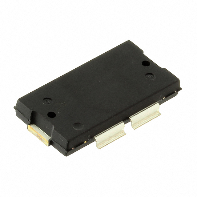
NXP Semiconductors AFT09MP055GNR1
- Part No.:
- AFT09MP055GNR1
- Manufacturer:
- NXP Semiconductors
- Category:
- Single FETs, MOSFETs
- Package:
- TO-270BB
- Datasheet:
-
 AFT09MP055GNR1.pdf
- Description:
- RF MOSFET LDMOS 12.5V TO270-4
- Quantity:
- Payment:

- Shipping:

Inventory:3,956
Please send an inquiry. Send us your inquiry, and we will respond immediately.
Product details
Overview
AFT09MP055GNR1 from NXP Semiconductors (formerly Freescale) is a 55 W, 764–941 MHz broadband RF power LDMOS transistor in TO-270WB-4 gull-wing package, designed for mobile two-way radio output stages. It delivers 57 W Pout at 870 MHz with 17.5 dB power gain and 69% drain efficiency under narrowband CW conditions (12.5 Vdc, IDQ(A+B) = 550 mA), and maintains ≥55 W across 764–870 MHz broadband operation.
For engineers reviewing the AFT09MP055GNR1 datasheet, AFT09MP055GNR1 pinout, AFT09MP055GNR1 application, or AFT09MP055GNR1 equivalent, key selection criteria include ruggedness under >65:1 VSWR load mismatch, integrated ESD protection (HBM Class 2), thermal resistance of 0.32 °C/W, and compatibility with TETRA/SSB linearity requirements.
Technical Context
This dual-gate, dual-drain LDMOS device operates in enhancement-mode with N-channel lateral structure, optimized for common-source Class AB amplifier configurations. Its integrated input matching network enables stable broadband performance without external tuning across 764–870 MHz, while the exposed backside source terminal provides low-inductance thermal path to heatsink.
The transistor supports high-ruggedness operation up to 225°C junction temperature and withstands 3 W CW overdrive at 870 MHz into >65:1 VSWR at all phase angles without degradation - verified per Freescale's load mismatch test methodology using 12.5 Vdc bias and 550 mA quiescent current.
Key Specifications
| Parameter | Value and Actual Design Meaning |
|---|---|
| Frequency Range | 764–941 MHz - fully characterized and validated for mobile radio bands including 700/800 MHz TETRA and SSB systems. |
| Output Power (Pout) | 57 W @ 870 MHz (narrowband), ≥55 W across 764–870 MHz (broadband) - enables single-device coverage of entire band without retuning. |
| Power Gain (Gps) | 17.5 dB @ 870 MHz (narrowband), 15.7–16.1 dB across 764–870 MHz - sufficient for driver-to-final stage amplification with margin. |
| Drain Efficiency (ηD) | 69% @ 870 MHz (narrowband), 56–61% across 764–870 MHz - reduces thermal load and DC supply demand in portable/base station radios. |
| Thermal Resistance (RθJC) | 0.32 °C/W - enables high-power operation with standard heatsinking; junction-to-case path optimized via exposed source pad. |
| Ruggedness | Withstands >65:1 VSWR at 870 MHz with 3 W CW overdrive - eliminates need for external circulators or VSWR protection circuitry in field-deployed radios. |
| ESD Protection | HBM Class 2 (2500 V), MM Class A (150 V), CDM Class IV (2000 V) - ensures robust handling during assembly and field maintenance. |
Pinout & Package
TO-270WB-4 gull-wing plastic package with exposed backside source terminal for direct thermal mounting. Package rated for 225°C case temperature and moisture sensitivity level 3 (peak reflow 260°C).
| Pin/Terminal | Circuit Role | Design Meaning |
|---|---|---|
| Drain A | RF power output terminal (side A) | Parallel-connected with Drain B for full 55 W output; requires low-inductance RF grounding via PCB microstrip. |
| Drain B | RF power output terminal (side B) | Electrically identical to Drain A; used in push-pull or parallel configuration to share current and thermal load. |
| Gate A | RF input control terminal (side A) | Bias and drive node for side A; matched impedance (1.40 – j1.00 Ω @ 870 MHz) enables broadband input matching. |
| Gate B | RF input control terminal (side B) | Independent gate for side B; allows differential or independent biasing; same impedance profile as Gate A. |
| Exposed Backside | Source terminal (common for both sides) | Primary thermal conduction path; must be soldered directly to copper heatsink area on PCB for RθJC = 0.32 °C/W performance. |
Key Features
| Feature | Design Value |
|---|---|
| Integrated Input Matching | Eliminates discrete matching components in 764–870 MHz band - reduces board space and tuning complexity in compact mobile radios. |
| High Ruggedness Architecture | Validated >65:1 VSWR tolerance at 870 MHz - enables reliable operation in antenna-mismatched field environments without protection circuitry. |
| 225°C Capable Plastic Package | Supports continuous operation at elevated ambient temperatures in sealed base station enclosures or vehicle-mounted radios. |
| Enhanced Thermal Performance | 0.32 °C/W junction-to-case resistance - allows 55 W output with <18°C temperature rise above heatsink at 25°C ambient. |
| High Linearity for TETRA/SSB | Optimized transconductance and capacitance profiles (Ciss = 690 pF, Crss = 1.9 pF) minimize adjacent channel interference in narrowband voice systems. |
Applications
| Base Station Transmitter Output Stage | Mobile Radio Final Amplifier |
|---|---|
Use Scenario: High-reliability 800 MHz TETRA base station transmitting up to 55 W ERP into shared antenna infrastructure with variable VSWR. IC Role / Device Role / Timing Role: Final-stage RF power amplifier operating in Class AB common-source configuration, driven by pre-driver stage. Use Value: >65:1 VSWR ruggedness prevents shutdown or damage during antenna cable faults or connector corrosion, ensuring uninterrupted dispatch communication. | Use Scenario: Vehicle-mounted 700 MHz public safety radio requiring compact, thermally efficient final amplifier capable of sustained 55 W output. IC Role / Device Role / Timing Role: Dual-drain LDMOS transistor configured in parallel for current sharing and thermal distribution across TO-270WB-4 footprint. Use Value: 0.32 °C/W RθJC enables operation with passive heatsinking only - eliminates need for forced-air cooling in space-constrained vehicular enclosures. |
| Portable Two-Way Radio PA Module | TETRA Handheld Radio Power Amplifier |
Use Scenario: Portable repeater unit deployed in remote locations where maintenance access is limited and thermal management is constrained. IC Role / Device Role / Timing Role: Broadband RF power transistor delivering ≥55 W across 764–870 MHz with integrated input matching network. Use Value: Eliminates external matching components and associated tuning labor - accelerates time-to-market for ruggedized portable radio designs. | Use Scenario: TETRA-compliant handheld radio requiring high linearity for 25 kHz channel spacing and low ACPR in battery-powered operation. IC Role / Device Role / Timing Role: Final-stage amplifier biased at IDQ(A+B) = 550 mA for optimal trade-off between efficiency and spectral purity. Use Value: Confirmed high linearity performance minimizes adjacent channel leakage, meeting ETSI EN 300 392-2 ACPR requirements without digital predistortion. |
Equivalent & Alternatives
The following parts are listed as comparable options for similar RF power amplifier applications.
| Alternative Part | Technical Difference | Application Difference | Selection Advice |
|---|---|---|---|
| MRF6V2010NR1 | 10 W Pout, 1.8–2.2 GHz range, lower power density, TO-270WB-4 package | Targeted for higher-frequency LTE small cells, not suitable for 700/800 MHz mobile radio bands | Select when operating above 1.8 GHz with lower power requirement and different thermal envelope. |
| AFT09MS055GNR1 | Same 55 W rating and 764–941 MHz range but uses silicon carbide (SiC) substrate; higher cost, improved thermal conductivity | Used in mission-critical military radios where extended MTTF and wider temperature margin are mandatory | Choose only if 225°C junction rating and enhanced reliability outweigh cost premium over LDMOS. |
Compared with MRF6V2010NR1 and AFT09MS055GNR1, the AFT09MP055GNR1 offers optimal balance of 55 W output, 764–941 MHz coverage, ruggedness, and cost for commercial/public safety mobile radios - neither alternative matches its combination of bandwidth, power, and proven field reliability in this frequency band.
Availability
AFT09MP055GNR1 is available at Aetrix Electronics and suitable for mobile radio base stations, vehicle-mounted transceivers, portable repeaters, and TETRA handheld radios requiring stable component supply across long production lifecycles.
Supply support for AFT09MP055GNR1 includes scheduled delivery planning, volume procurement assistance, BOM continuity management, traceable sourcing, and lifecycle availability coordination for OEM customers, industrial embedded developers, connected-device designers, and electronics production programs.
Manufacturer
NXP Semiconductors is a global semiconductor leader focused on secure connectivity solutions for automotive, industrial, and communications markets, with deep heritage in RF power from its Freescale acquisition.
The Airfast® RF Power portfolio - which includes AFT09MP055GNR1 - was specifically engineered for high-efficiency, high-ruggedness mobile two-way radio amplifiers operating in licensed 700/800 MHz bands.
FAQ
What is the maximum continuous drain current rating for AFT09MP055GNR1?
The AFT09MP055GNR1 does not specify a maximum continuous drain current in absolute terms; instead, it defines safe operating conditions via maximum ratings: total device dissipation is 625 W at TC = 25°C (derating 3.13 W/°C above), with VDSS = +40 Vdc and IDQ(A+B) = 550 mA typical for narrowband operation. Actual current depends on bias point, thermal design, and RF loading - the datasheet emphasizes thermal resistance (0.32 °C/W) and ruggedness testing over current limits. For AFT09MP055GNR1, junction temperature must remain ≤225°C under all operating conditions.
Does AFT09MP055GNR1 require external input matching components?
No, AFT09MP055GNR1 features integrated input matching optimized for 764–870 MHz broadband operation, eliminating the need for external matching networks in Freescale reference circuits. The device's input impedance is characterized as 1.40 – j1.00 Ω at 870 MHz (narrowband) and varies across the band (e.g., 1.24 + j0.09 Ω at 760 MHz), but the internal matching enables full 55 W output without discrete components - confirmed in both narrowband test fixture and broadband reference circuit documentation for AFT09MP055GNR1.
What is the gate threshold voltage range for AFT09MP055GNR1?
The gate threshold voltage (VGS(th)) for AFT09MP055GNR1 is specified as 1.6–2.6 Vdc (typical 2.1 Vdc) measured at VDS = 10 Vdc and ID = 270 μAdc. This range reflects process variation across production lots and ensures consistent turn-on behavior in Class AB bias networks. The datasheet confirms this parameter applies to both sides of the dual-gate device, and AFT09MP055GNR1 must be biased within this window to achieve specified IDQ(A+B) = 550–800 mA quiescent current and avoid cutoff or excessive conduction.
Can AFT09MP055GNR1 be used in pulsed RF applications?
Yes, AFT09MP055GNR1 is qualified for pulsed RF operation, though the primary characterization data (gain, efficiency, ruggedness) is provided for CW conditions. Its LDMOS structure supports pulse widths down to microseconds with appropriate gate drive and thermal management. The device's 0.32 °C/W RθJC and 225°C junction rating enable short-duration high-peak-power pulses, and Freescale's load mismatch testing (CW overdrive) demonstrates inherent pulse robustness. For AFT09MP055GNR1 pulsed designs, users must validate duty cycle, peak current, and thermal cycling against the absolute maximum ratings table.
What is the recommended PCB layout practice for the exposed source pad of AFT09MP055GNR1?
The exposed backside of the AFT09MP055GNR1 package is the source terminal and must be soldered directly to a large, low-thermal-resistance copper area on the PCB - ideally a dedicated thermal pad connected to internal ground planes via ≥6 thermal vias (0.3 mm diameter, filled or plated). Freescale reference designs use 0.030″ thick FR-4 with εr = 4.8 and specify microstrip routing for RF paths; for AFT09MP055GNR1, the source pad must be isolated from signal traces and grounded exclusively to minimize inductance and maximize heat transfer, ensuring the specified 0.32 °C/W RθJC is achieved.
AFT09MP055GNR1 Specifications
- Product attributes
- Attribute value
- Manufacturer:
- NXP Semiconductors
- Series:
- -
- Package/Case:
- TO-270BB
- Packaging:
- Tape & Reel (TR)
- Product Status:
- Active
- Technology:
- LDMOS
- Configuration:
- -
- Frequency:
- 870MHz
- Gain:
- 15.7dB
- Voltage - Test:
- 12.5 V
- Current Rating (Amps):
- -
- Noise Figure:
- -
- Current - Test:
- 550 mA
- Power - Output:
- 1W
- Voltage - Rated:
- 40 V
- Grade:
- -
- Qualification:
- -
- Mounting Type:
- Surface Mount
- Supplier Device Package:
- TO-270 WB-4 Gull
AFT09MP055GNR1 FAQ
1.How can I place an order for AFT09MP055GNR1 through Aetrix?
Please submit a Request for Quotation (RFQ) for AFT09MP055GNR1 on Aetrix. Our sales agent will provide a competitive quotation and guide you through the order confirmation once you accept the terms.
2.Are the price and stock information for AFT09MP055GNR1 reliable?
The price and inventory of AFT09MP055GNR1 are updated periodically and may fluctuate due to market conditions. Stock and pricing data are typically refreshed every 24 hours. Quotation validity for AFT09MP055GNR1 is usually 5 days.
3.What payment methods are accepted for AFT09MP055GNR1?
We accept Wire Transfer, PayPal, Credit Card, Western Union, MoneyGram, and Escrow for AFT09MP055GNR1 transactions.
Note: Certain payment methods may incur a processing fee.
4.How is shipping managed for AFT09MP055GNR1?
AFT09MP055GNR1 orders can be shipped via leading logistics carriers, including DHL, UPS, FedEx, TNT, or Registered Mail.
Once your AFT09MP055GNR1 order is processed, you will receive an email with the shipment details and tracking number.
Note: Tracking information may take up to 24 hours to appear. Express delivery typically takes 3–5 business days.
5.How can I obtain technical support or documentation for AFT09MP055GNR1?
For technical support, including AFT09MP055GNR1 datasheets, pinout diagrams, or application guidance, please contact our engineering support team. They can provide detailed documentation and assistance for your AFT09MP055GNR1 requirements.
6.How does Aetrix verify that AFT09MP055GNR1 is sourced from the original manufacturer or authorized distributors?
All AFT09MP055GNR1 products on Aetrix are procured from qualified distributors and authorized channels. Our dedicated quality assurance team conducts strict verification, including traceability checks and, if necessary, third-party testing. This ensures that AFT09MP055GNR1 meets industry standards.
7.What is the process for return or replacement of AFT09MP055GNR1?
All AFT09MP055GNR1 units undergo pre-shipment inspection (PSI). If there is an issue with AFT09MP055GNR1, returns or replacements are accepted under the following conditions:
1.Quantity discrepancies, incorrect items, or visible external defects (such as breakage or corrosion), acknowledged by Aetrix.
2.The issue is reported within 90 days of delivery.
3.The AFT09MP055GNR1 part is unused and in its original packaging.
Return procedure for AFT09MP055GNR1:
1.Submit a request within 90 days.
2.Obtain a Return Material Authorization (RMA) from Aetrix.
AFT09MP055GNR1 Tags
-
3SK294(TE85L,F)
Toshiba Semiconductor and Storage

-
SAV-551+
Mini-Circuits

-
TAV2-501+
Mini-Circuits
-
CE3514M4-C2
CEL
-
AFT05MS004NT1
NXP USA Inc.
-
SAV-541+
Mini-Circuits
-
CE3512K2-C1
CEL
-
AFM907NT1
NXP Semiconductors
-
SKY65050-372LF
Skyworks Solutions Inc.
-
CE3520K3-C1
CEL
-
AFT09MS007NT1
NXP USA Inc.
-
AFT09MS015NT1
NXP USA Inc.
Tech Hub

A practical engineering guide to 3.3V and 5V logic compatibility, input thresholds, resistor dividers, translator ICs, MOSFET level shifting, I2C pull-ups, timing limits and power-sequencing risks.

The 74HC595 uses push-pull logic outputs, while the TPIC6B595 uses 50 V open-drain DMOS sinks for higher-power loads. This guide compares timing, current limits, 3.3 V interfacing, load wiring, thermal…

The 74HC595 converts serial data into eight stable parallel outputs. This guide covers pin functions, shift and storage timing, OE and MR behavior, drive-current limits, cascading, voltage compatibilit…

A technical comparison of level-sensitive latches and edge-triggered flip-flops, covering timing windows, setup and hold limits, master–slave operation, time borrowing, race-through, HDL inference and…

A D latch stores one bit while Enable controls when data can pass. This reference covers gate-level operation, truth tables, transparency, setup and hold timing, LE versus OE, common ICs and practical …

An SR latch stores one bit through cross-coupled feedback. This engineering reference covers NOR and NAND implementations, truth tables, forbidden-state recovery, gated operation, switch debouncing, fa…

Latch circuits retain one bit through feedback. This technical reference covers SR and D latches, truth tables, transparency, timing limits, latch-versus-flip-flop behavior, applications and common log…

An engineering guide to LED driver operation, constant-current and constant-voltage outputs, linear and switching topologies, dimming, IC selection, calculations, replacement compatibility, and fault c…

Operational amplifier guide covering op amp basics, feedback, ideal vs real op amps, common configurations, buffer circuits, offset, bias current, gain-bandwidth, slew rate, rail-to-rail limits and sel…

Jumper cables guide covering safe connection order, red and black clamp placement, final ground connection, cable gauge, length, clamp quality, copper vs CCA cables, jump starter comparison and battery…


