
 My Inquiry
 My Account


Asahi Kasei Microdevices/AKM AK1220
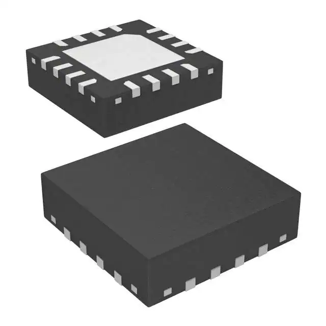
- Part No.:
- AK1220
- Manufacturer:
- Asahi Kasei Microdevices/AKM
- Category:
- RF Mixers
- Package:
- 16-UFQFN Exposed Pad
- Datasheet:
-
 AK1220.pdf
- Description:
- IC RF MIXER 100-900MHZ 16UQFN
- Quantity:
- Payment:

- Shipping:

Inventory:2,764
Please send an inquiry. Send us your inquiry, and we will respond immediately.
Product details
Overview
The AK1220 from Asahi Kasei Microdevices is a high-linearity passive down-conversion mixer IC with RF input (100–900 MHz), LO input (−5 to +5 dBm, 100–900 MHz), and differential open-drain IF output (20–100 MHz). It features selectable linearity–power trade-off via BIAS pin resistor (22 kΩ or 56 kΩ), single-ended 50 Ω RF interface, complementary 50 Ω LO inputs, and operates from 4.75–5.25 V. It is used in analog radio front-ends for PMR/LMR transceivers requiring high IIP3 and stable noise figure.
For engineers reviewing the AK1220 datasheet, AK1220 pinout, AK1220 application, or AK1220 equivalent, key selection considerations include its dual-power-mode linearity optimization (IIP3 up to +22 dBm at 17 mA), differential IF output architecture requiring external power feeding, 16-pin UQFN package (3 mm × 3 mm, 0.5 mm pitch), and compatibility with balun- or LC-based IF impedance matching networks.
Technical Context
The AK1220 implements a double-balanced Gilbert-cell mixer topology with integrated LO buffer and on-chip bias control. Its RF path accepts single-ended 50 Ω signals while LO ports require complementary drive; IF outputs are open-drain differential, necessitating external inductive power feeding and load termination.
Linearity and gain are dynamically adjustable via a single external resistor on the BIAS pin-enabling discrete selection between two operating points: 17 mA / +22 dBm IIP3 / 1 dB conversion gain or 9 mA / +11 dBm IIP3 / 0.5 dB gain. Performance remains stable across −40°C to +85°C and supply voltages from 4.75 V to 5.25 V.
Key Specifications
| Parameter | Value and Actual Design Meaning |
|---|---|
| RF Frequency Range | 100–900 MHz: supports full-band PMR, LMR, marine, and amateur radio bands without re-tuning. |
| LO Input Level | −5 to +5 dBm: compatible with low-power synthesizers and eliminates need for external LO amplification. |
| IF Output Range | 20–100 MHz: enables baseband or low-IF architectures with standard SAW/BAW filtering and ADC interfacing. |
| IIP3 (High-Linearity Mode) | +22 dBm @ 17 mA: suppresses third-order intermodulation in dense RF environments (e.g., multi-channel repeaters). |
| SSB Noise Figure | 10.5 dB @ 17 mA: maintains SNR integrity in weak-signal reception scenarios typical of handheld radios. |
| Conversion Gain | 1 dB (17 mA) / 0.5 dB (9 mA): near-unity gain simplifies IF chain design and minimizes cascaded noise impact. |
| Supply Voltage | 4.75–5.25 V: matches standard 5 V rail systems and tolerates ±2.5% regulation variation. |
| Operating Temperature | −40°C to +85°C: qualified for industrial and outdoor mobile radio deployments. |
Pinout & Package
AK1220 uses a 16-pin UQFN package (3.0 mm × 3.0 mm × 0.60 mm, 0.5 mm pitch) with exposed thermal pad. Pin 1 is marked by a dot; NC pins should be grounded per recommendation but do not affect electrical performance if left floating.
| Pin/Terminal | Circuit Role | Design Meaning |
|---|---|---|
| RFIN | RF Input | Single-ended 50 Ω port; requires series inductor to ground for optimal matching across 100–900 MHz. |
| VSS | Ground | Primary ground reference; connects to exposed pad for thermal and RF grounding. |
| LOINN | LO Input Negative | Complementary LO input; must be decoupled to ground with 100 pF capacitor. |
| LOINP | LO Input Positive | Complementary LO input; matched 50 Ω differential pair with LOINN. |
| NC | No Connect | Unused internal node; recommended to tie to ground for mechanical stability. |
| BIAS | Bias Current Control | Analog I/O pin; sets operating current (and thus IIP3/gain/NF) via external resistor to ground (22 kΩ or 56 kΩ). |
| VDD | Power Supply | 4.75–5.25 V supply; bypassed with 100 pF capacitor close to pin. |
| IFOUTN | IF Output Negative | Differential open-drain output; requires external inductor for power feeding and 2.2 kΩ load to VDD. |
| IFOUTP | IF Output Positive | Differential open-drain output; paired with IFOUTN to deliver balanced IF signal. |
Key Features
| Feature | Design Value |
|---|---|
| Linearity–Power Selectable Architecture | Two discrete operating modes: 17 mA/+22 dBm IIP3 or 9 mA/+11 dBm IIP3-enables system-level power vs. dynamic range trade-off. |
| Differential Open-Drain IF Outputs | Eliminates need for external IF transformers in some designs; supports flexible LC or balun-based single-ended conversion. |
| Wide RF and LO Bandwidth | 100–900 MHz coverage allows single-part support across VHF/UHF PMR, marine, and amateur bands without redesign. |
| Integrated LO Buffer | Reduces LO drive requirements and improves port-to-port isolation (RF–LO leakage < −30 dBc typical). |
| Thermally Optimized UQFN | Exposed pad enhances thermal dissipation under continuous 17 mA operation in compact handheld form factors. |
Applications
| Two-way Radios (PMR/LMR) | Radio Communications for Disaster Prevention |
|---|---|
Use Scenario: Portable transceivers deployed in emergency response teams requiring simultaneous multi-channel monitoring and interference-resistant voice transmission. IC Role / Device Role / Timing Role: Down-conversion mixer in receiver front-end, translating 400–470 MHz PMR band to 45 MHz IF for demodulation. Use Value: +22 dBm IIP3 prevents desensitization from nearby strong interferers during critical communications. |
Use Scenario: Fixed-site repeater systems installed in seismic or flood-prone areas, operating continuously under wide temperature swings. IC Role / Device Role / Timing Role: Core RF mixer in diversity-reception receivers, converting 136–174 MHz VHF band to 10.7 MHz IF. Use Value: −40°C to +85°C rating and stable NF (10.5 dB) ensure reliable weak-signal recovery in harsh environmental conditions. |
| Marine Radios | Amateur Radios |
Use Scenario: Class D DSC-capable VHF marine radios operating in salt-laden, high-humidity coastal environments. IC Role / Device Role / Timing Role: First-stage mixer in dual-conversion receiver, down-converting 156–174 MHz marine band to 45 MHz IF. Use Value: 50 Ω RF input and complementary LO simplify matching to ruggedized front-end filters and LNAs. |
Use Scenario: Home-built HF/VHF transceivers where designers manually optimize linearity vs. battery life. IC Role / Device Role / Timing Role: Configurable mixer enabling either high-dynamic-range receive (22 kΩ BIAS) or low-power standby (56 kΩ BIAS). Use Value: Single-resistor tuning of IIP3 (22 dBm → 11 dBm) and current (17 mA → 9 mA) reduces component count and board space. |
Equivalent & Alternatives
The following parts are listed as comparable options for similar down-conversion mixer applications.
| Alternative Part | Technical Difference | Application Difference | Selection Advice |
|---|---|---|---|
| AK1222 | Lower quiescent current (2.9 mA), reduced IIP3 (+13 dBm), same RF/LO/IF frequency ranges. | Targeted at battery-powered portable radios where ultra-low power dominates over linearity. | Select AK1222 when average current draw must stay below 3 mA and +13 dBm IIP3 suffices for local-band operation. |
| AK1224 | Lower noise figure (8.5 dB), moderate IIP3 (+18 dBm), identical frequency coverage and package. | Preferred in weak-signal, narrowband applications like digital voice decoding where NF outweighs third-order suppression. | Choose AK1224 when SSB NF is prioritized over IIP3-e.g., in trunked radio control channel receivers. |
Compared with AK1222 and AK1224, the AK1220 uniquely delivers the highest IIP3 (+22 dBm) within the AK12xx family while retaining full 100–900 MHz bandwidth and UQFN compatibility-making it optimal for interference-heavy multi-channel infrastructure and professional-grade handhelds.
Availability
The AK1220 is available at Aetrix Electronics and suitable for two-way radios (PMR/LMR), disaster prevention communication systems, marine VHF radios, and amateur radio transceivers requiring stable component supply, consistent parametric performance, and long-term manufacturability.
Supply support for AK1220 includes scheduled delivery planning, volume procurement assistance, BOM continuity management, traceable sourcing, and lifecycle availability coordination for OEM customers, industrial embedded developers, connected-device designers, and electronics production programs.
Manufacturer
Asahi Kasei Microdevices Corporation (AKM) is a Japanese semiconductor company specializing in mixed-signal ICs for audio, sensor, and RF applications, with emphasis on high-performance analog front-ends and low-noise signal conditioning.
The AK1220 belongs to AKM's high-linearity RF mixer product line, designed specifically for analog receiver front-ends in professional land-mobile radio, maritime, and emergency communications equipment demanding robust intermodulation immunity.
FAQ
What is the recommended external resistor value for the BIAS pin to achieve maximum IIP3 in the AK1220?
The AK1220 achieves its maximum IIP3 of +22 dBm when a 22 kΩ resistor is connected between the BIAS pin and ground, drawing 17 mA total supply current. This configuration also yields 1 dB conversion gain and 10.5 dB SSB noise figure. The resistor tolerance should be ≤5% to maintain specification compliance across temperature and voltage variations.
How is power delivered to the differential IF outputs of the AK1220?
The AK1220 IFOUTP and IFOUTN pins are open-drain outputs and require external DC power feeding via inductors-typically 1000–2200 nH-connected between VDD and each IF pin. A 2.2 kΩ load resistor is placed between IFOUTP and IFOUTN to set the differential output impedance. Without this inductive power feed, no IF signal is generated.
Does the AK1220 require external baluns for RF or IF interfacing?
The AK1220 does not require baluns for RF input (single-ended 50 Ω) but supports both balun- and LC-based IF output conversion. Its differential IF outputs can be converted to single-ended using either a wideband balun (e.g., Mini-Circuits ADT4-6T+) or an LC network with calculated L/C values-both methods are validated in the AK1220 evaluation board schematics.
What is the absolute maximum RF input power rating for the AK1220?
The AK1220 has an absolute maximum RF input power rating of +12 dBm, as specified in Table 2 of the MS1165-E-03 datasheet. Exceeding this level may cause permanent damage. For reliable operation, RF input power should remain ≤0 dBm under normal conditions, especially when operating in high-IIP3 mode with 22 kΩ BIAS resistor.
Can the AK1220 be used in up-conversion applications?
No-the AK1220 is designed exclusively for down-conversion mixing (RF → IF). Its internal architecture, biasing scheme, and characterization data (e.g., IIP3, NF, conversion gain) are specified only for down-conversion operation. For up-conversion, AKM recommends the AK1228, which supports 10 MHz–2 GHz bidirectional mixing with 3 V supply.
AK1220 Specifications
- Product attributes
- Attribute value
- Manufacturer:
- Asahi Kasei Microdevices/AKM
- Series:
- -
- Package/Case:
- 16-UFQFN Exposed Pad
- Packaging:
- Tape & Reel (TR)
- Product Status:
- Obsolete
- RF Type:
- -
- Frequency:
- 100MHz ~ 900MHz
- Number of Mixers:
- 1
- Gain:
- 1dB
- Noise Figure:
- 10.5dB
- Secondary Attributes:
- -
- Current - Supply:
- 24mA
- Voltage - Supply:
- 4.75V ~ 5.25V
- Mounting Type:
- Surface Mount
- Supplier Device Package:
- 16-UQFN (3x3)
AK1220 FAQ
1.How can I place an order for AK1220 through Aetrix?
Please submit a Request for Quotation (RFQ) for AK1220 on Aetrix. Our sales agent will provide a competitive quotation and guide you through the order confirmation once you accept the terms.
2.Are the price and stock information for AK1220 reliable?
The price and inventory of AK1220 are updated periodically and may fluctuate due to market conditions. Stock and pricing data are typically refreshed every 24 hours. Quotation validity for AK1220 is usually 5 days.
3.What payment methods are accepted for AK1220?
We accept Wire Transfer, PayPal, Credit Card, Western Union, MoneyGram, and Escrow for AK1220 transactions.
Note: Certain payment methods may incur a processing fee.
4.How is shipping managed for AK1220?
AK1220 orders can be shipped via leading logistics carriers, including DHL, UPS, FedEx, TNT, or Registered Mail.
Once your AK1220 order is processed, you will receive an email with the shipment details and tracking number.
Note: Tracking information may take up to 24 hours to appear. Express delivery typically takes 3–5 business days.
5.How can I obtain technical support or documentation for AK1220?
For technical support, including AK1220 datasheets, pinout diagrams, or application guidance, please contact our engineering support team. They can provide detailed documentation and assistance for your AK1220 requirements.
6.How does Aetrix verify that AK1220 is sourced from the original manufacturer or authorized distributors?
All AK1220 products on Aetrix are procured from qualified distributors and authorized channels. Our dedicated quality assurance team conducts strict verification, including traceability checks and, if necessary, third-party testing. This ensures that AK1220 meets industry standards.
7.What is the process for return or replacement of AK1220?
All AK1220 units undergo pre-shipment inspection (PSI). If there is an issue with AK1220, returns or replacements are accepted under the following conditions:
1.Quantity discrepancies, incorrect items, or visible external defects (such as breakage or corrosion), acknowledged by Aetrix.
2.The issue is reported within 90 days of delivery.
3.The AK1220 part is unused and in its original packaging.
Return procedure for AK1220:
1.Submit a request within 90 days.
2.Obtain a Return Material Authorization (RMA) from Aetrix.
AK1220 Tags
-
MAX2671EUT+T
Analog Devices Inc./Maxim Integrated

-
ADEX-10+
Mini-Circuits
-
ADE-2+
Mini-Circuits
-
ADE-1+
Mini-Circuits
-
LT5560EDD#PBF
Analog Devices Inc.
-
LT5560EDD#TRPBF
Analog Devices Inc.

-
LTC5562IUC#TRPBF
Analog Devices Inc.
-
MAX2681EUT+T
Analog Devices Inc./Maxim Integrated
-
ADE-1ASK+
Mini-Circuits
-
ADE-1L+
Mini-Circuits
-
ADL5350ACPZ-R7
Analog Devices Inc.
-
AD608ARZ-RL
Analog Devices Inc.
Tech Hub

A practical engineering and sourcing framework covering lifecycle verification, lifetime-buy calculations, replacement qualification, supplier checks and counterfeit-risk controls.

TTL and CMOS logic families differ in thresholds, loading, output drive, power and timing. This engineering guide compares 74HC and 74HCT, calculates noise margins and checks 3.3 V/5 V compatibility.

A practical engineering guide to 3.3V and 5V logic compatibility, input thresholds, resistor dividers, translator ICs, MOSFET level shifting, I2C pull-ups, timing limits and power-sequencing risks.

The 74HC595 uses push-pull logic outputs, while the TPIC6B595 uses 50 V open-drain DMOS sinks for higher-power loads. This guide compares timing, current limits, 3.3 V interfacing, load wiring, thermal…

The 74HC595 converts serial data into eight stable parallel outputs. This guide covers pin functions, shift and storage timing, OE and MR behavior, drive-current limits, cascading, voltage compatibilit…

A technical comparison of level-sensitive latches and edge-triggered flip-flops, covering timing windows, setup and hold limits, master–slave operation, time borrowing, race-through, HDL inference and…

A D latch stores one bit while Enable controls when data can pass. This reference covers gate-level operation, truth tables, transparency, setup and hold timing, LE versus OE, common ICs and practical …

An SR latch stores one bit through cross-coupled feedback. This engineering reference covers NOR and NAND implementations, truth tables, forbidden-state recovery, gated operation, switch debouncing, fa…

Latch circuits retain one bit through feedback. This technical reference covers SR and D latches, truth tables, transparency, timing limits, latch-versus-flip-flop behavior, applications and common log…

An engineering guide to LED driver operation, constant-current and constant-voltage outputs, linear and switching topologies, dimming, IC selection, calculations, replacement compatibility, and fault c…


