
 My Inquiry
 My Account


STMicroelectronics ALED6001TR
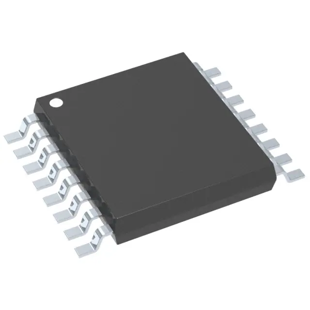
- Part No.:
- ALED6001TR
- Manufacturer:
- STMicroelectronics
- Category:
- LED Drivers
- Package:
- 16-PowerTSSOP (0.173", 4.40mm Width)
- Datasheet:
-
 ALED6001TR.pdf
- Description:
- IC LED DRIVER CTRLR PWM 16HTSSOP
- Quantity:
- Payment:

- Shipping:

Inventory:1,813
Please send an inquiry. Send us your inquiry, and we will respond immediately.
Product details
Overview
ALED6001 from STMicroelectronics is an AEC-Q101 qualified automotive LED driver IC integrating a peak-current-mode boost controller, high-side current sensing (30–300 mV differential), ±4% output current reference accuracy, 5.5–36 V input range, and dedicated PWM dimming control (PWMI/PWMO) for single-string high-brightness LED applications including daytime running lights and fog lights.
For engineers reviewing the ALED6001 datasheet, ALED6001 pinout, ALED6001 application, or ALED6001 equivalent, this device supports boost/SEPIC/buck-boost topologies, delivers up to 60 V output, features dual LDOs (3.3 V/5 V), thermal shutdown with autorestart, and fault reporting via open-drain XFAULT - critical for automotive exterior lighting reliability and functional safety compliance.
Technical Context
The ALED6001 implements a fixed-frequency peak-current-mode boost controller with externally adjustable switching frequency (100–1000 kHz) and synchronization capability. Its high-side current sensing architecture uses VFBP/VFBN inputs referenced to PGND/SGND, enabling robust short-to-ground protection when paired with a P-channel MOSFET.
LED brightness control combines digital PWM (via PWMI input and PWMO gate driver output) and analog dimming (ADIM pin, 0.3–1.2 V linear control). Fault management includes output overvoltage (OVFB threshold: 1.20 V), open-load detection (differential VFB < –120 mV), and cycle-by-cycle OCP at CSNS (360 mV typ.), all reported through XFAULT.
Key Specifications
| Parameter | Value and Actual Design Meaning |
|---|---|
| Input Voltage Range | 5.5 V to 36 V - supports full automotive battery range including cold-crank (6 V) and load-dump (36 V) transients. |
| Output Current Accuracy | ±4% over temperature and production spread - enables precise luminance control without calibration in DRL/headlamp modules. |
| Switching Frequency | 100 kHz to 1 MHz (adjustable via FSW resistor or sync signal) - balances EMI suppression and efficiency in space-constrained headlight PCBs. |
| Current Sense Range | 30 mV to 300 mV differential (VFBP–VFBN) - allows low-power, high-accuracy shunt design minimizing heat and board area. |
| Thermal Shutdown Threshold | 150 °C to 175 °C with 40 °C hysteresis - ensures safe operation under sustained high-power LED drive and ambient temperature extremes. |
| Shutdown Current | <10 µA at TJ ≤ 25 °C - meets ultra-low quiescent current requirements for always-on automotive lighting systems. |
| Fault Reporting | Open-drain XFAULT with 0.2 V low-level voltage at 4 mA - directly interfaces with microcontroller GPIO for ASIL-B–compatible diagnostics. |
Pinout & Package
Package: HTSSOP-16 with exposed thermal pad (electrically connected to PGND/SGND), optimized for automotive thermal cycling and high-power density layouts.
| Pin/Terminal | Circuit Role | Design Meaning |
|---|---|---|
| PWMI | Enable + PWM dimming input | Dual-function digital input: ≥100 µs high pulse enables device; PWM duty cycle controls LED brightness. |
| FSW | Frequency setting / sync input | Resistor-to-SGND sets fSW (100–1000 kHz); tied to LDO3 for fixed 600 kHz or accepts external clock for multi-device synchronization. |
| XFAULT | Fault indicator output | Open-drain output pulled low on overtemperature, OVFB, or LED overcurrent - enables system-level fault logging. |
| LDO3 | 3.3 V LDO output | Supplies internal logic and ADIM/COMP circuitry; requires 1 µF MLCC to SGND for stability and noise immunity. |
| CSNS | Power switch OCP input | Connects to MOSFET source; detects overcurrent via 360 mV threshold with slope compensation injection for CCM stability. |
| VFBP / VFBN | High-side current sense inputs | Differential pair referenced to PGND/SGND; measures shunt voltage across LED string for ±4% regulation accuracy. |
| GATE | External MOSFET gate driver | Drives boost switch with 3 Ω pull-up / 1 Ω pull-down resistance; rise/fall times <30 ns support high-fSW operation. |
| PWMO | PWM dimming output | Phase-aligned gate driver for external N-MOSFET dimming switch; eliminates need for level-shifting or external drivers. |
Key Features
| Feature | Design Value |
|---|---|
| AEC-Q101 qualification | Validated for automotive underhood environments: –40 °C to +150 °C junction temperature, HBM ±2 kV, CDM ±750 V. |
| Topology flexibility | Supports boost, SEPIC, and floating buck-boost - enables single IC solution across DRL, position light, and fog lamp designs. |
| Integrated dual LDOs | 3.3 V (20 mA) and 5 V (40 mA) regulators eliminate external bias supplies, reducing BOM count and layout complexity. |
| High-side sensing architecture | Enables direct connection of LED anode to battery; protects against short-to-ground failure mode common in automotive harnesses. |
| Programmable soft-start | Fixed 3.5 ms internal soft-start prevents inrush current during turn-on - avoids fuse tripping and EMI spikes in shared power rails. |
| Comprehensive fault coverage | Detects thermal shutdown, output overvoltage (open LED), output short-circuit, and sensing resistor failure - meets ISO 26262 diagnostic coverage targets. |
Applications
| Daytime Running Lights (DRL) | Automotive Fog Lights |
|---|---|
|
Use Scenario: Constant-current LED string driven from 12 V battery with dynamic dimming during daylight transitions. IC Role / Device Role / Timing Role: Primary LED current regulator and topology controller; manages boost conversion, PWM dimming timing, and fault response within 100 µs. Use Value: ±4% current accuracy ensures consistent lumen output across temperature; XFAULT reporting enables fail-safe shutdown per UNECE R149 compliance. |
Use Scenario: High-output LED array operating in humid, vibration-prone front bumper environment with frequent on/off cycles. IC Role / Device Role / Timing Role: High-side current sensing controller with thermal autorestart and short-circuit detection - maintains illumination during intermittent faults. Use Value: 150 °C thermal shutdown with 40 °C hysteresis prevents permanent damage during thermal overload; HTSSOP-16 exposed pad ensures reliable heat dissipation. |
| Low Beam Headlights | Position Lights / Blinkers |
|
Use Scenario: Adaptive low-beam module requiring analog dimming for glare-free ADB functionality alongside PWM for flash-to-pass. IC Role / Device Role / Timing Role: Dual-mode brightness controller using ADIM (0.3–1.2 V) for fine analog adjustment and PWMI/PWMO for fast PWM modulation. Use Value: Linear ADIM response enables smooth lumen ramping; PWMO's 50 ns rise time supports >10 kHz dimming for flicker-free operation. |
Use Scenario: Compact rear-position light with integrated blinker function requiring minimal external components and low standby current. IC Role / Device Role / Timing Role: Low-quiescent LED driver with 10 µA shutdown current and integrated 3.3 V LDO powering MCU interface circuitry. Use Value: Eliminates need for separate LDO; shutdown delay (10 ms) prevents false turn-off during transient supply dips in CAN-controlled lighting systems. |
Equivalent & Alternatives
The following parts are listed as comparable options for similar automotive LED driver applications.
| Alternative Part | Technical Difference | Application Difference | Selection Advice |
|---|---|---|---|
| MAX20050ATP/V+T | Integrated MOSFET (no external switch required); lower max output voltage (40 V vs. 60 V); no ADIM analog dimming pin. | Better suited for compact, low-power position lights; lacks high-voltage capability for long LED strings in fog/low-beam. | Select when board space is critical and output voltage ≤40 V; avoid where high-side sensing or analog dimming is required. |
| TPS92692QPWPRQ1 | Current-mode buck-boost controller only (no boost-only mode); higher quiescent current (2.5 mA vs. 1.7 mA); no integrated 5 V LDO. | Requires external gate driver and bias supply; better for wide-input, constant-output applications like interior lighting. | Choose for buck-boost-only topologies with tight input/output voltage overlap; not drop-in for boost-based DRL/fog light designs. |
Compared with MAX20050ATP/V+T and TPS92692QPWPRQ1, the ALED6001 uniquely combines boost topology support, 60 V output capability, high-side sensing, and dual PWM/analog dimming - making it the only option validated for AEC-Q101-compliant high-brightness exterior lighting with functional safety diagnostics.
Availability
ALED6001 is available at Aetrix Electronics and suitable for automotive exterior lighting, daytime running lights, and fog lights requiring stable component supply across extended product lifecycles and rigorous environmental qualification.
Supply support for ALED6001 includes scheduled delivery planning, volume procurement assistance, BOM continuity management, traceable sourcing, and lifecycle availability coordination for OEM customers, industrial embedded developers, connected-device designers, and electronics production programs.
Manufacturer
STMicroelectronics is a global semiconductor leader specializing in automotive, industrial, and power management solutions, with over 30 years of automotive-grade IC development and AEC-Q100/Q101 certification expertise.
The ALED6001 belongs to ST's automotive LED driver product line, engineered specifically for high-reliability exterior lighting systems demanding functional safety, thermal resilience, and topology flexibility in harsh vehicle environments.
FAQ
What topologies does the ALED6001 support, and how is topology selection implemented?
The ALED6001 supports boost, SEPIC, and floating buck-boost topologies - selected entirely by external component configuration, not internal register settings. No firmware or configuration is needed: boost uses a standard inductor-diode output; SEPIC adds a coupling capacitor; floating buck-boost relocates the inductor to the output side. All share the same IC pinout and control loop.
How does the ALED6001 achieve ±4% LED current accuracy across temperature and production spread?
Accuracy is achieved through trimmed internal reference circuitry, matched high-side sensing amplifier design (VFBP/VFBN), and factory-calibrated gain path - verified across –40 °C to +125 °C and statistical process control during wafer sort. No external trimming or calibration is required in end equipment.
Can the ALED6001 drive multiple LED strings, and what limits its channel count?
No - the ALED6001 is strictly a single-channel driver, with one COMP loop, one CSNS input, and one VFBP/VFBN pair. Driving multiple strings would require separate ALED6001 ICs synchronized via the FSW pin, as each unit regulates only one current-sense path and cannot share feedback or protection signals.
What is the role of the TPAD thermal pad, and how must it be connected on the PCB?
The TPAD is an electrically grounded thermal pad (connected internally to PGND and SGND) that must be soldered to a minimum 100 mm² copper pour tied to the system ground plane. It reduces Rth,JA by up to 15 °C/W and is mandatory for operation above 1.2 A output current or ambient temperatures exceeding 85 °C.
ALED6001TR Specifications
- Product attributes
- Attribute value
- Manufacturer:
- STMicroelectronics
- Series:
- -
- Package/Case:
- 16-PowerTSSOP (0.173", 4.40mm Width)
- Packaging:
- Tape & Reel (TR)
- Product Status:
- Active
- Type:
- DC DC Controller
- Topology:
- SEPIC, Step-Down (Buck), Step-Up (Boost)
- Internal Switch(s):
- No
- Number of Outputs:
- 1
- Voltage - Supply (Min):
- 5.5V
- Voltage - Supply (Max):
- 36V
- Voltage - Output:
- -
- Current - Output / Channel:
- -
- Frequency:
- 1MHz
- Dimming:
- Analog, PWM
- Applications:
- -
- Operating Temperature:
- -40°C ~ 150°C (TJ)
- Grade:
- Automotive
- Qualification:
- AEC-Q100
- Mounting Type:
- Surface Mount
- Supplier Device Package:
- 16-HTSSOP
ALED6001TR FAQ
1.How can I place an order for ALED6001TR through Aetrix?
Please submit a Request for Quotation (RFQ) for ALED6001TR on Aetrix. Our sales agent will provide a competitive quotation and guide you through the order confirmation once you accept the terms.
2.Are the price and stock information for ALED6001TR reliable?
The price and inventory of ALED6001TR are updated periodically and may fluctuate due to market conditions. Stock and pricing data are typically refreshed every 24 hours. Quotation validity for ALED6001TR is usually 5 days.
3.What payment methods are accepted for ALED6001TR?
We accept Wire Transfer, PayPal, Credit Card, Western Union, MoneyGram, and Escrow for ALED6001TR transactions.
Note: Certain payment methods may incur a processing fee.
4.How is shipping managed for ALED6001TR?
ALED6001TR orders can be shipped via leading logistics carriers, including DHL, UPS, FedEx, TNT, or Registered Mail.
Once your ALED6001TR order is processed, you will receive an email with the shipment details and tracking number.
Note: Tracking information may take up to 24 hours to appear. Express delivery typically takes 3–5 business days.
5.How can I obtain technical support or documentation for ALED6001TR?
For technical support, including ALED6001TR datasheets, pinout diagrams, or application guidance, please contact our engineering support team. They can provide detailed documentation and assistance for your ALED6001TR requirements.
6.How does Aetrix verify that ALED6001TR is sourced from the original manufacturer or authorized distributors?
All ALED6001TR products on Aetrix are procured from qualified distributors and authorized channels. Our dedicated quality assurance team conducts strict verification, including traceability checks and, if necessary, third-party testing. This ensures that ALED6001TR meets industry standards.
7.What is the process for return or replacement of ALED6001TR?
All ALED6001TR units undergo pre-shipment inspection (PSI). If there is an issue with ALED6001TR, returns or replacements are accepted under the following conditions:
1.Quantity discrepancies, incorrect items, or visible external defects (such as breakage or corrosion), acknowledged by Aetrix.
2.The issue is reported within 90 days of delivery.
3.The ALED6001TR part is unused and in its original packaging.
Return procedure for ALED6001TR:
1.Submit a request within 90 days.
2.Obtain a Return Material Authorization (RMA) from Aetrix.
ALED6001TR Tags

-
BCR402RE6327HTSA1
Infineon Technologies

-
BCR430UXTSA2
Infineon Technologies

-
BCR420UE6433HTMA1
Infineon Technologies
-
BCR420UE6327HTSA1
Infineon Technologies
-
BCR421UE6327HTSA1
Infineon Technologies

-
LYT1604D-TL
Power Integrations

-
HV9910CLG-G
Microchip Technology

-
CL2N8-G
Microchip Technology

-
BCR420UW6-7
Diodes Incorporated
-
BCR421UW6-7
Diodes Incorporated

-
BCR420UFD-7
Diodes Incorporated
-
BCR421UFD-7
Diodes Incorporated
Tech Hub

A practical engineering and sourcing framework covering lifecycle verification, lifetime-buy calculations, replacement qualification, supplier checks and counterfeit-risk controls.

TTL and CMOS logic families differ in thresholds, loading, output drive, power and timing. This engineering guide compares 74HC and 74HCT, calculates noise margins and checks 3.3 V/5 V compatibility.

A practical engineering guide to 3.3V and 5V logic compatibility, input thresholds, resistor dividers, translator ICs, MOSFET level shifting, I2C pull-ups, timing limits and power-sequencing risks.

The 74HC595 uses push-pull logic outputs, while the TPIC6B595 uses 50 V open-drain DMOS sinks for higher-power loads. This guide compares timing, current limits, 3.3 V interfacing, load wiring, thermal…

The 74HC595 converts serial data into eight stable parallel outputs. This guide covers pin functions, shift and storage timing, OE and MR behavior, drive-current limits, cascading, voltage compatibilit…

A technical comparison of level-sensitive latches and edge-triggered flip-flops, covering timing windows, setup and hold limits, master–slave operation, time borrowing, race-through, HDL inference and…

A D latch stores one bit while Enable controls when data can pass. This reference covers gate-level operation, truth tables, transparency, setup and hold timing, LE versus OE, common ICs and practical …

An SR latch stores one bit through cross-coupled feedback. This engineering reference covers NOR and NAND implementations, truth tables, forbidden-state recovery, gated operation, switch debouncing, fa…

Latch circuits retain one bit through feedback. This technical reference covers SR and D latches, truth tables, transparency, timing limits, latch-versus-flip-flop behavior, applications and common log…

An engineering guide to LED driver operation, constant-current and constant-voltage outputs, linear and switching topologies, dimming, IC selection, calculations, replacement compatibility, and fault c…


