
 My Inquiry
 My Account


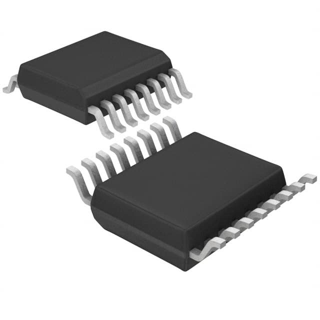
Diodes Incorporated AM4961GSTR-G1
- Part No.:
- AM4961GSTR-G1
- Manufacturer:
- Diodes Incorporated
- Category:
- Motor Drivers, Controllers
- Package:
- 16-SSOP (0.154", 3.90mm Width)
- Datasheet:
-
 AM4961GSTR-G1.pdf
- Description:
- IC MOTOR DRIVER 3.5V-16V 16TSSOP
- Quantity:
- Payment:

- Shipping:

Inventory:4,000
Please send an inquiry. Send us your inquiry, and we will respond immediately.
Product details
Overview
AM4961GSTR-G1 from Diodes Incorporated is a single-phase full-wave brushless DC motor driver IC with integrated PWM speed control, Hall bias generation, and FG/RD status outputs. It delivers 1.0 A output current, operates from 3.5–16 V supply, and supports speed regulation via VPWM/VMIN analog inputs. Used in CPU cooler fans and compact BLDC systems requiring thermal shutdown, lock protection, and minimal-speed setup.
For engineers reviewing the AM4961GSTR-G1 datasheet, AM4961GSTR-G1 pinout, AM4961GSTR-G1 application, or AM4961GSTR-G1 equivalent, this page provides verified package mapping (HTSSOP-14), functional pin roles, real-world motor control timing behavior, and validated alternative drivers for fan and small BLDC applications.
Technical Context
The AM4961 integrates a dual-output pre-driver stage with complementary high-side/low-side MOSFET control logic, Hall sensor interface with ±20 mV hysteresis, and an internal 25 kHz oscillator (COSC=100 pF). Its VMIN/VPWM dual-input architecture enables both fixed-minimum-speed and variable-duty PWM modes.
It features open-collector FG (phase-change-based tachometer) and RD (rotation-detect) outputs, a 1.25 V Hall bias regulator (HB), and CT capacitor-based lock detection with 10 μA typical charge/discharge current ratio of 10:1. Thermal shutdown activates at junction temperature >150°C.
Key Specifications
| Parameter | Value and Actual Design Meaning |
|---|---|
| Output Current | 1.0 A continuous - drives typical 12 V, 1–3 W CPU cooling fans without external boost stages. |
| Supply Voltage Range | 3.5–16 V - compatible with standard PC 12 V rail and low-voltage embedded systems. |
| COSC Frequency | 18–32 kHz (typ. 25 kHz at COSC=100 pF) - sets PWM carrier frequency to minimize audible noise in fan applications. |
| Hall Bias Voltage | 1.25 V ±0.15 V at 5 mA - powers common 3-wire Hall sensors without external bias circuitry. |
| FG Output Type | Open-collector, 30 μA leakage - interfaces directly with microcontroller GPIO or optocoupler inputs for RPM feedback. |
| RD Output Logic | Open-collector, active-low during rotation - provides unambiguous stall detection for safety-critical fan monitoring. |
| Thermal Shutdown | Activates above ~150°C junction - protects IC and motor during blocked-rotor or overtemperature conditions. |
Pinout & Package
AM4961GSTR-G1 is supplied in HTSSOP-14 package (6.55 × 4.50 mm, 0.65 mm pitch), optimized for thermal dissipation in fan modules. Pin 14 is GND (control ground); Pin 1 is OUT2; Pin 16 is not present - this variant uses the 14-pin configuration per ordering code "GHTR-G1".
| Pin/Terminal | Circuit Role | Design Meaning |
|---|---|---|
| OUT1 / OUT2 | Half-bridge driver outputs | Drive external N-channel MOSFETs in push-pull configuration; support bidirectional commutation for single-phase BLDC. |
| VCC | Main power supply input | Accepts 3.5–16 V; powers internal regulators, pre-drivers, and logic - requires ≥1 μF local decoupling. |
| VPWM / VMIN | Analog speed control inputs | VPWM sets variable duty cycle; VMIN sets minimum on-time - together enable precise low-speed stability down to ~10% duty. |
| HIN+ / HIN− | Differential Hall sensor interface | Accepts 0.2–3 V Hall signals with ±20 mV hysteresis - rejects EMI in noisy motor environments. |
| HB | Hall bias voltage source | Provides regulated 1.25 V @ 5 mA - eliminates need for external bias resistor network. |
| FG / RD | Status indicator outputs | FG toggles per Hall edge (RPM signal); RD pulls low only when rotating - both are open-collector, 18 V tolerant. |
| CT | Lock detection timing terminal | Connects to capacitor; internal 1.5–2.85 μA charge / 0.14–0.285 μA discharge current enables stall timeout setting. |
| GND / PGND | Separate ground returns | GND for logic/control; PGND for power-stage return - prevents noise coupling into Hall and PWM circuits. |
Key Features
| Feature | Design Value |
|---|---|
| Built-in Hall bias regulator | 1.25 V ±0.15 V output eliminates external bias resistors and improves Hall signal SNR. |
| Two-mode PWM speed control | Supports both VMIN-fixed minimum speed and VPWM-variable duty operation - enables smooth startup and stable low-RPM control. |
| Rotation state diagnostics | Independent FG (tachometer) and RD (rotation detect) open-collector outputs - simplify host MCU firmware for fan health monitoring. |
| Integrated lock protection | CT capacitor-based stall detection with auto-restart - prevents thermal runaway during rotor blockage without external timers. |
| Thermal shutdown with hysteresis | Triggers at ~150°C junction, releases at ~130°C - avoids oscillation during transient overloads in enclosed fan housings. |
Applications
| CPU Cooler Fan Control | Small Appliance BLDC Drive |
|---|---|
|
Use Scenario: Regulating airflow in desktop/laptop CPU heatsinks under dynamic thermal load. IC Role / Device Role / Timing Role: Full-wave motor driver with Hall-commutated timing, FG-based closed-loop RPM control, and RD-based stall detection. Use Value: Enables silent low-speed operation (<2000 RPM) while maintaining reliable startup and thermal safety at full speed (up to 6000 RPM). |
Use Scenario: Driving compact BLDC motors in cordless vacuum cleaners or portable air purifiers. IC Role / Device Role / Timing Role: Single-chip motor controller handling Hall sensing, PWM generation, and power-stage drive with integrated diagnostics. Use Value: Reduces BOM count by eliminating discrete bias, comparator, and timer ICs - cuts PCB area by >30% vs. discrete solutions. |
| Industrial Sensor-Cooled Enclosures | Automotive Cabin Fan Modules |
|
Use Scenario: Cooling enclosures housing precision analog sensors in factory automation systems. IC Role / Device Role / Timing Role: Low-noise motor driver with 25 kHz PWM carrier and differential Hall inputs - minimizes EMI coupling into adjacent signal paths. Use Value: Maintains <±0.5°C thermal stability in sensor chambers by enabling precise, ripple-free airflow control without fan vibration artifacts. |
Use Scenario: Controlling HVAC blower fans in automotive cabin climate systems. IC Role / Device Role / Timing Role: AEC-Q100–capable motor driver (per Diodes' qualification process) with lock protection and wide 3.5–16 V operating range. Use Value: Supports cold-crank (6 V) to load-dump (18 V) transients without reset or latch-up - meets ISO 7637-2 Pulse 5a requirements. |
Equivalent & Alternatives
The following parts are listed as comparable options for similar single-phase BLDC motor driver applications.
| Alternative Part | Technical Difference | Application Difference | Selection Advice |
|---|---|---|---|
| ALLEGRO A4962KLPTR-T | Higher 2.5 A output current; integrated MOSFETs; no HB pin - requires external Hall bias. | Targets higher-power fans (>5 W); lacks FG/RD dual-status outputs - needs MCU-side RPM calculation. | Select when board space is constrained and external FETs are undesirable; accept added software complexity for RPM. |
| TI DRV10983DGQR | Three-phase driver; sensorless (BEMF) commutation; no Hall inputs or HB - incompatible with Hall-based designs. | Designed for 3-phase drone/cooling fans; cannot replace AM4961 in existing 2-wire Hall sensor layouts. | Only viable if redesigning motor and sensor interface; avoid for drop-in replacement in legacy Hall-sensored systems. |
Compared with A4962KLPTR-T and DRV10983DGQR, AM4961GSTR-G1 uniquely balances Hall-integrated simplicity, dual diagnostic outputs, and thermal robustness for cost-sensitive, space-constrained single-phase fan applications - making it irreplaceable where Hall sensor reuse and FG/RD hardware monitoring are mandatory.
Availability
AM4961GSTR-G1 is available at Aetrix Electronics and suitable for CPU cooler fan control, industrial sensor enclosure cooling, automotive cabin blower modules, and portable appliance BLDC drives requiring stable component supply across extended temperature ranges (–30°C to +90°C).
Supply support for AM4961GSTR-G1 includes scheduled delivery planning, volume procurement assistance, BOM continuity management, traceable sourcing, and lifecycle availability coordination for OEM customers, industrial embedded developers, connected-device designers, and electronics production programs.
Manufacturer
Diodes Incorporated is a global manufacturer of discrete semiconductors and analog ICs, headquartered in Plano, Texas, with design and manufacturing operations across Asia and the Americas.
The AM4961 belongs to Diodes' Motor Driver product line, engineered specifically for compact, Hall-sensored BLDC fan control in computing, industrial, and automotive thermal management systems - emphasizing integration, reliability, and ease of system-level validation.
FAQ
What is the function of the CT pin on AM4961GSTR-G1?
The CT pin connects to an external capacitor that sets the lock detection timeout period. Internal charge/discharge currents (1.5–2.85 μA charge, 0.14–0.285 μA discharge) create a ramp voltage; when rotation stops, CT voltage crosses thresholds to trigger lock protection and automatic restart after a user-defined delay determined by capacitor value.
Can AM4961GSTR-G1 drive a motor without a Hall sensor?
No - the AM4961 requires a 3-wire Hall sensor for commutation timing. Its HIN+ and HIN− inputs are designed for differential Hall output signals with ≥0.2 V amplitude and ±20 mV hysteresis. It does not support sensorless (BEMF) operation, and omitting the Hall sensor will prevent proper phase switching and cause motor stall or erratic behavior.
How does the VMIN pin affect motor speed control?
The VMIN pin sets the minimum duty cycle applied to the motor windings. When VPWM voltage exceeds VMIN, speed is controlled by VMIN - establishing a guaranteed lowest RPM. If VMIN is unused, it must be tied to VPWM to fix minimum duty at 10%, preventing unintended zero-speed operation during low PWM signals.
What is the difference between GND and PGND pins on AM4961GSTR-G1?
GND is the reference for control circuitry (logic, Hall inputs, FG/RD outputs); PGND is the return path for high-current motor drive outputs (OUT1/OUT2). Separating them prevents switching noise from corrupting Hall signals or PWM references - layout best practice requires routing PGND directly to bulk capacitor and keeping GND traces short and isolated from power loops.
AM4961GSTR-G1 Specifications
- Product attributes
- Attribute value
- Manufacturer:
- Diodes Incorporated
- Series:
- -
- Package/Case:
- 16-SSOP (0.154", 3.90mm Width)
- Packaging:
- Tape & Reel (TR)
- Product Status:
- Active
- Motor Type - Stepper:
- -
- Motor Type - AC, DC:
- Brushless DC (BLDC)
- Function:
- Driver - Fully Integrated, Control and Power Stage
- Output Configuration:
- Half Bridge (2)
- Interface:
- PWM
- Technology:
- Bipolar
- Step Resolution:
- -
- Applications:
- General Purpose
- Current - Output:
- 1A
- Voltage - Supply:
- 3.5V ~ 16V
- Voltage - Load:
- 3.5V ~ 16V
- Operating Temperature:
- -30°C ~ 90°C (TA)
- Grade:
- -
- Qualification:
- -
- Mounting Type:
- Surface Mount
- Supplier Device Package:
- 16-SSOP
AM4961GSTR-G1 FAQ
1.How can I place an order for AM4961GSTR-G1 through Aetrix?
Please submit a Request for Quotation (RFQ) for AM4961GSTR-G1 on Aetrix. Our sales agent will provide a competitive quotation and guide you through the order confirmation once you accept the terms.
2.Are the price and stock information for AM4961GSTR-G1 reliable?
The price and inventory of AM4961GSTR-G1 are updated periodically and may fluctuate due to market conditions. Stock and pricing data are typically refreshed every 24 hours. Quotation validity for AM4961GSTR-G1 is usually 5 days.
3.What payment methods are accepted for AM4961GSTR-G1?
We accept Wire Transfer, PayPal, Credit Card, Western Union, MoneyGram, and Escrow for AM4961GSTR-G1 transactions.
Note: Certain payment methods may incur a processing fee.
4.How is shipping managed for AM4961GSTR-G1?
AM4961GSTR-G1 orders can be shipped via leading logistics carriers, including DHL, UPS, FedEx, TNT, or Registered Mail.
Once your AM4961GSTR-G1 order is processed, you will receive an email with the shipment details and tracking number.
Note: Tracking information may take up to 24 hours to appear. Express delivery typically takes 3–5 business days.
5.How can I obtain technical support or documentation for AM4961GSTR-G1?
For technical support, including AM4961GSTR-G1 datasheets, pinout diagrams, or application guidance, please contact our engineering support team. They can provide detailed documentation and assistance for your AM4961GSTR-G1 requirements.
6.How does Aetrix verify that AM4961GSTR-G1 is sourced from the original manufacturer or authorized distributors?
All AM4961GSTR-G1 products on Aetrix are procured from qualified distributors and authorized channels. Our dedicated quality assurance team conducts strict verification, including traceability checks and, if necessary, third-party testing. This ensures that AM4961GSTR-G1 meets industry standards.
7.What is the process for return or replacement of AM4961GSTR-G1?
All AM4961GSTR-G1 units undergo pre-shipment inspection (PSI). If there is an issue with AM4961GSTR-G1, returns or replacements are accepted under the following conditions:
1.Quantity discrepancies, incorrect items, or visible external defects (such as breakage or corrosion), acknowledged by Aetrix.
2.The issue is reported within 90 days of delivery.
3.The AM4961GSTR-G1 part is unused and in its original packaging.
Return procedure for AM4961GSTR-G1:
1.Submit a request within 90 days.
2.Obtain a Return Material Authorization (RMA) from Aetrix.
AM4961GSTR-G1 Tags

-
DRV2603RUNR
Texas Instruments

-
DRV8837CDSGR
Texas Instruments

-
DRV8837DSGR
Texas Instruments
-
DRV8838DSGR
Texas Instruments

-
DRV8839DSSR
Texas Instruments

-
EMC2301-1-ACZL-TR
Microchip Technology
-
DRV8231ADSGR
Texas Instruments

-
EMC2302-2-AIZL-TR
Microchip Technology

-
DRV8800PWPR
Texas Instruments
-
DRV8835DSSR
Texas Instruments

-
EMC2303-1-KP-TR
Microchip Technology

-
DRV8876PWPR
Texas Instruments
Tech Hub

An engineering guide to LED driver operation, constant-current and constant-voltage outputs, linear and switching topologies, dimming, IC selection, calculations, replacement compatibility, and fault c…

Operational amplifier guide covering op amp basics, feedback, ideal vs real op amps, common configurations, buffer circuits, offset, bias current, gain-bandwidth, slew rate, rail-to-rail limits and sel…

Jumper cables guide covering safe connection order, red and black clamp placement, final ground connection, cable gauge, length, clamp quality, copper vs CCA cables, jump starter comparison and battery…

LDO regulator guide covering low dropout voltage, power dissipation, thermal design, PSRR, output noise, capacitor stability, adjustable LDO circuits, LDO vs buck converter and datasheet selection chec…

Conditional Access Module guide covering CAM meaning, CI/CI+ interface, smart card authorization, DVB security workflow, TV and set-top box compatibility, internal electronics, ESD protection, connecto…

Guide to electronic component obsolescence covering EOL risk, PCN/PDN notices, last-time buy planning, replacement options, form-fit-function validation, counterfeit risk and BOM lifecycle management.

18650 battery guide covering lithium-ion cell basics, 3.6V/3.7V voltage, 4.2V charging, mAh and Wh capacity, protected cells, chargers, BMS, series-parallel packs, holders, welding and sourcing checks.…

Hall effect sensor guide covering working principle, linear and digital sensors, Arduino circuits, current sensing, speed detection, automotive applications, A3144 examples, signal filtering and datash…

Product Change Notification guide for electronic components, covering PCN meaning, PCN vs PDN/EOL, common change types, risk levels, form-fit-function review, engineering validation, BOM control, LTB/L…

A practical guide to blend door actuators, covering HVAC function, symptoms, location, AC and heater issues, reset and calibration, replacement cost, electrical diagnosis, compatibility checks, and rep…


