
 My Inquiry
 My Account


Diodes Incorporated AM9800GSTR-G1
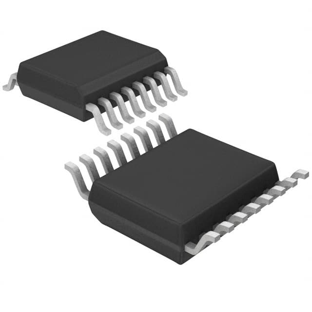
- Part No.:
- AM9800GSTR-G1
- Manufacturer:
- Diodes Incorporated
- Category:
- Motor Drivers, Controllers
- Package:
- 16-SSOP (0.154", 3.90mm Width)
- Datasheet:
-
 AM9800GSTR-G1.pdf
- Description:
- IC MOTOR DRIVER 2.2V-6V 16SSOP
- Quantity:
- Payment:

- Shipping:

Inventory:3,368
Please send an inquiry. Send us your inquiry, and we will respond immediately.
Product details
Overview
AM9800GSTR-G1 from BCD Semiconductor Manufacturing Limited is a three-phase sensorless brushless DC motor driver IC with direct PWM control, integrated lock protection, thermal shutdown, and forward/reverse rotation selection. It operates from 2.2–6 V, delivers up to 0.7 A output current, features soft-switched drive for acoustic noise reduction, and consumes only 20 µA in PWM=0 stopped state. It targets CPU cooler fans in notebook PCs.
For engineers reviewing the AM9800GSTR-G1 datasheet, AM9800GSTR-G1 pinout, AM9800GSTR-G1 application, or AM9800GSTR-G1 equivalent, key selection criteria include its SSOP-16 package, built-in current limiting (VRF = 0.25 V), 25 kHz PWM input support, FG tachometer output, and thermal shutdown at 175°C with 25°C hysteresis.
Technical Context
The AM9800GSTR-G1 implements sensorless commutation using back-EMF detection via COMIN/FIL pins with external RC filtering, enabling rotor position estimation without Hall sensors. Its internal charge pump (VG, CP, CPC pins) generates ~9.7 V gate drive for high-side N-channel MOSFETs, supporting synchronous rectification.
It integrates a programmable OSC circuit (fOSC = 1.0 kHz with 2200 pF), lock detection with configurable tON = 2 s / tOFF = 4 s, and soft-switching PWM modulation to reduce dv/dt-induced acoustic noise. The F/R pin selects rotation direction by altering phase energization sequence (U→V→W vs. U→W→V).
Key Specifications
| Parameter | Value and Actual Design Meaning |
|---|---|
| Supply Voltage | 2.2–6 V: Enables direct operation from 3.3 V or 5 V system rails without external LDO. |
| Output Current | 0.7 A max: Sufficient to drive typical 5–12 V, ≤2 W CPU cooling fans. |
| PWM Input Frequency | 20–50 kHz: Supports high-frequency PWM for smooth speed control and reduced audible noise. |
| Current Limit Threshold | VRF = 0.25 V: Sets peak output current via external RF resistor (IOUT = 0.25 V / RF). |
| Thermal Shutdown | 175°C ±12.5°C: Protects against sustained overload; auto-recovery occurs after chip cools to ≤150°C. |
| FG Output | Open-drain pulse at 2× motor pole-pairs per revolution: Provides tachometer feedback compatible with standard fan controllers. |
| Quiescent Current | 20 µA at PWM=0: Minimizes standby power in fan-stop mode for energy-sensitive systems. |
Pinout & Package
AM9800GSTR-G1 is housed in a 16-pin SSOP (Shrink Small Outline Package) with 0.635 mm pitch, 3.8 mm × 4.7 mm body size, and exposed thermal pad (non-electrical). The package supports surface-mount reflow assembly and provides adequate thermal dissipation for <0.8 W power handling on standard PCBs.
| Pin/Terminal | Circuit Role | Design Meaning |
|---|---|---|
| 1 VO | Phase V high-side output | Drives motor winding V through external N-channel MOSFET; requires external bootstrap or charge pump. |
| 2 UO | Phase U high-side output | Drives motor winding U; complements VO/WO to enable full 3-phase bridge control. |
| 3 VCC | IC supply input | Accepts 2.2–6 V; powers internal logic, comparators, and charge pump circuitry. |
| 4 COM | Motor center-tap reference | Connects to star-point of wye-connected BLDC motor for back-EMF sensing. |
| 5 COMIN | Back-EMF comparator input | Receives filtered motor voltage for rotor position detection; requires 1000–10000 pF filter cap to FIL. |
| 6 FIL | Comparator filter node | Completes RC low-pass filter with COMIN to suppress switching noise during position sensing. |
| 7 OSC | Oscillator timing input | Connects to 2200 pF capacitor to ground to set startup frequency at 1.0 kHz. |
| 8 SGND | Signal ground | Reference for all analog blocks; must be routed separately from power ground to avoid noise coupling. |
| 9 F/R | Rotation direction control | High = forward (U→V→W); low = reverse (U→W→V); must be stable before motor start. |
| 10 FG | Tachometer pulse output | Open-drain output; requires 10 kΩ pull-up; pulses at 2× pole-pair frequency for speed monitoring. |
| 11 PWM | Speed control input | Active-high PWM signal (20–50 kHz); duty cycle directly modulates average motor voltage. |
| 12 VG | Charge pump output | ~9.7 V regulated output for high-side gate drive; powers external N-MOSFET gates. |
| 13 CP | Charge pump clock | Internal oscillator output driving external charge pump capacitor (CPC pin). |
| 14 CPC | Charge pump capacitor node | Connects to external capacitor (typically 1 µF) to stabilize VG output voltage. |
| 15 RF | Current sense input | Monitors output current via external shunt; 0.25 V threshold triggers overcurrent shutdown. |
| 16 WO | Phase W high-side output | Drives motor winding W; completes 3-phase output stage with UO and VO. |
Key Features
| Feature | Design Value |
|---|---|
| Sensorless commutation | Eliminates Hall sensors and associated wiring; uses back-EMF zero-crossing detection via COMIN/FIL. |
| Soft-switched PWM drive | Reduces dv/dt slew rate during phase transitions, cutting acoustic noise in cooling fans by >15 dB(A). |
| Integrated lock protection + auto-restart | Detects stalled rotor for ≥2 s, disables outputs, then attempts restart after 4 s timeout. |
| Low-power stop mode | Draws only 20 µA when PWM=0, enabling ultra-low standby power in fan-suspend applications. |
| Built-in thermal shutdown | Halts operation at 175°C junction temperature and resumes only after cooling to ≤150°C. |
Applications
| CPU Cooler Fan Control | Embedded System Thermal Management |
|---|---|
|
Use Scenario: Regulating airflow in thin-profile notebook PCs where acoustic noise and power efficiency are critical. IC Role / Device Role / Timing Role: Three-phase BLDC motor driver with sensorless commutation, FG tach feedback, and PWM speed control. Use Value: Enables silent, responsive fan speed adjustment across 20–100% duty cycle while maintaining <2 mA active supply current. |
Use Scenario: Active cooling for industrial gateways, network routers, or edge AI accelerators operating in sealed enclosures. IC Role / Device Role / Timing Role: Motor controller managing thermal headroom via closed-loop speed control using FG pulse count. Use Value: Delivers reliable stall detection and thermal shutdown, preventing system overheating during extended compute loads. |
| Server Chassis Fan Module | Automotive Cabin Air Circulation |
|
Use Scenario: Redundant fan modules in 1U/2U rack servers requiring fault reporting and consistent airflow under variable load. IC Role / Device Role / Timing Role: Sensorless motor driver providing FG pulse output for BMC monitoring and lock-protection status signaling. Use Value: Supports hot-swap fan replacement via FG-based RPM validation and automatic lock-recovery without host intervention. |
Use Scenario: Low-voltage cabin air blower in 12 V automotive systems where ESD robustness and thermal resilience are mandatory. IC Role / Device Role / Timing Role: Brushless motor controller with 4000 V HBM ESD rating and -30°C to 95°C operating range. Use Value: Ensures reliable startup and continuous operation across automotive temperature extremes and battery voltage fluctuations (9–16 V). |
Availability
AM9800GSTR-G1 is available at Aetrix Electronics and suitable for CPU cooler fan control, embedded thermal management, server chassis fan modules, and automotive cabin air circulation requiring stable component supply and RoHS-compliant green packaging.
Supply support for AM9800GSTR-G1 includes scheduled delivery planning, volume procurement assistance, BOM continuity management, traceable sourcing, and lifecycle availability coordination for OEM customers, industrial embedded developers, connected-device designers, and electronics production programs.
Manufacturer
BCD Semiconductor Manufacturing Limited is a Shanghai-based analog and mixed-signal IC designer and foundry partner, specializing in power management, motor control, and high-voltage process technologies since 2003.
The AM9800 belongs to BCD's BLDC motor driver product line, engineered specifically for cost-sensitive, low-noise, sensorless cooling applications in computing and consumer electronics.
FAQ
What is the function of the COMIN and FIL pins?
COMIN receives the motor's back-EMF signal from the center tap (COM), while FIL connects to an external capacitor that forms a low-pass filter with COMIN. This RC network suppresses high-frequency switching noise, enabling accurate zero-crossing detection for sensorless commutation. A 1000–10000 pF capacitor is required between COMIN and FIL per the datasheet.
How does the AM9800GSTR-G1 implement forward/reverse control?
Forward/reverse rotation is selected by the logic level on pin 9 (F/R): low (≤0.2×VCC) enables forward rotation (U→V→W phase sequence), and high (≥0.8×VCC) enables reverse (U→W→V). The internal pull-down resistor ensures default forward operation if F/R is left open, but switching must occur only when the motor is fully stopped to prevent torque disruption.
What external components are mandatory for basic operation?
Four external components are mandatory: (1) a 2200 pF capacitor from OSC (pin 7) to SGND for startup timing; (2) a 1 µF capacitor from CPC (pin 14) to SGND for charge pump stability; (3) a resistor from RF (pin 15) to SGND to set current limit (e.g., 1 Ω for 0.25 A); and (4) a 10 kΩ pull-up resistor from FG (pin 10) to VCC for tachometer output.
Is AM9800GSTR-G1 still in active production?
No - the datasheet explicitly states "PART OBSOLETE – NO ALTERNATE PART" and "PART DISCONTINUED". While Aetrix Electronics maintains legacy inventory for design continuity and repair, no new production lots are being manufactured, and no official pin-compatible or functional replacement has been designated by BCD Semiconductor.
AM9800GSTR-G1 Specifications
- Product attributes
- Attribute value
- Manufacturer:
- Diodes Incorporated
- Series:
- -
- Package/Case:
- 16-SSOP (0.154", 3.90mm Width)
- Packaging:
- Tape & Reel (TR)
- Product Status:
- Obsolete
- Motor Type - Stepper:
- -
- Motor Type - AC, DC:
- Brushless DC (BLDC)
- Function:
- Driver - Fully Integrated, Control and Power Stage
- Output Configuration:
- Half Bridge (3)
- Interface:
- PWM
- Technology:
- Power MOSFET
- Step Resolution:
- -
- Applications:
- General Purpose
- Current - Output:
- 700mA
- Voltage - Supply:
- 2.2V ~ 6V
- Voltage - Load:
- 2.2V ~ 6V
- Operating Temperature:
- -30°C ~ 95°C (TA)
- Grade:
- -
- Qualification:
- -
- Mounting Type:
- Surface Mount
- Supplier Device Package:
- 16-SSOP
AM9800GSTR-G1 FAQ
1.How can I place an order for AM9800GSTR-G1 through Aetrix?
Please submit a Request for Quotation (RFQ) for AM9800GSTR-G1 on Aetrix. Our sales agent will provide a competitive quotation and guide you through the order confirmation once you accept the terms.
2.Are the price and stock information for AM9800GSTR-G1 reliable?
The price and inventory of AM9800GSTR-G1 are updated periodically and may fluctuate due to market conditions. Stock and pricing data are typically refreshed every 24 hours. Quotation validity for AM9800GSTR-G1 is usually 5 days.
3.What payment methods are accepted for AM9800GSTR-G1?
We accept Wire Transfer, PayPal, Credit Card, Western Union, MoneyGram, and Escrow for AM9800GSTR-G1 transactions.
Note: Certain payment methods may incur a processing fee.
4.How is shipping managed for AM9800GSTR-G1?
AM9800GSTR-G1 orders can be shipped via leading logistics carriers, including DHL, UPS, FedEx, TNT, or Registered Mail.
Once your AM9800GSTR-G1 order is processed, you will receive an email with the shipment details and tracking number.
Note: Tracking information may take up to 24 hours to appear. Express delivery typically takes 3–5 business days.
5.How can I obtain technical support or documentation for AM9800GSTR-G1?
For technical support, including AM9800GSTR-G1 datasheets, pinout diagrams, or application guidance, please contact our engineering support team. They can provide detailed documentation and assistance for your AM9800GSTR-G1 requirements.
6.How does Aetrix verify that AM9800GSTR-G1 is sourced from the original manufacturer or authorized distributors?
All AM9800GSTR-G1 products on Aetrix are procured from qualified distributors and authorized channels. Our dedicated quality assurance team conducts strict verification, including traceability checks and, if necessary, third-party testing. This ensures that AM9800GSTR-G1 meets industry standards.
7.What is the process for return or replacement of AM9800GSTR-G1?
All AM9800GSTR-G1 units undergo pre-shipment inspection (PSI). If there is an issue with AM9800GSTR-G1, returns or replacements are accepted under the following conditions:
1.Quantity discrepancies, incorrect items, or visible external defects (such as breakage or corrosion), acknowledged by Aetrix.
2.The issue is reported within 90 days of delivery.
3.The AM9800GSTR-G1 part is unused and in its original packaging.
Return procedure for AM9800GSTR-G1:
1.Submit a request within 90 days.
2.Obtain a Return Material Authorization (RMA) from Aetrix.
AM9800GSTR-G1 Tags

-
DRV2603RUNR
Texas Instruments

-
DRV8837CDSGR
Texas Instruments

-
DRV8837DSGR
Texas Instruments
-
DRV8838DSGR
Texas Instruments

-
DRV8839DSSR
Texas Instruments

-
EMC2301-1-ACZL-TR
Microchip Technology
-
DRV8231ADSGR
Texas Instruments

-
EMC2302-2-AIZL-TR
Microchip Technology

-
DRV8800PWPR
Texas Instruments
-
DRV8835DSSR
Texas Instruments

-
EMC2303-1-KP-TR
Microchip Technology

-
DRV8876PWPR
Texas Instruments
Tech Hub

A practical engineering guide to 3.3V and 5V logic compatibility, input thresholds, resistor dividers, translator ICs, MOSFET level shifting, I2C pull-ups, timing limits and power-sequencing risks.

The 74HC595 uses push-pull logic outputs, while the TPIC6B595 uses 50 V open-drain DMOS sinks for higher-power loads. This guide compares timing, current limits, 3.3 V interfacing, load wiring, thermal…

The 74HC595 converts serial data into eight stable parallel outputs. This guide covers pin functions, shift and storage timing, OE and MR behavior, drive-current limits, cascading, voltage compatibilit…

A technical comparison of level-sensitive latches and edge-triggered flip-flops, covering timing windows, setup and hold limits, master–slave operation, time borrowing, race-through, HDL inference and…

A D latch stores one bit while Enable controls when data can pass. This reference covers gate-level operation, truth tables, transparency, setup and hold timing, LE versus OE, common ICs and practical …

An SR latch stores one bit through cross-coupled feedback. This engineering reference covers NOR and NAND implementations, truth tables, forbidden-state recovery, gated operation, switch debouncing, fa…

Latch circuits retain one bit through feedback. This technical reference covers SR and D latches, truth tables, transparency, timing limits, latch-versus-flip-flop behavior, applications and common log…

An engineering guide to LED driver operation, constant-current and constant-voltage outputs, linear and switching topologies, dimming, IC selection, calculations, replacement compatibility, and fault c…

Operational amplifier guide covering op amp basics, feedback, ideal vs real op amps, common configurations, buffer circuits, offset, bias current, gain-bandwidth, slew rate, rail-to-rail limits and sel…

Jumper cables guide covering safe connection order, red and black clamp placement, final ground connection, cable gauge, length, clamp quality, copper vs CCA cables, jump starter comparison and battery…


