
 My Inquiry
 My Account


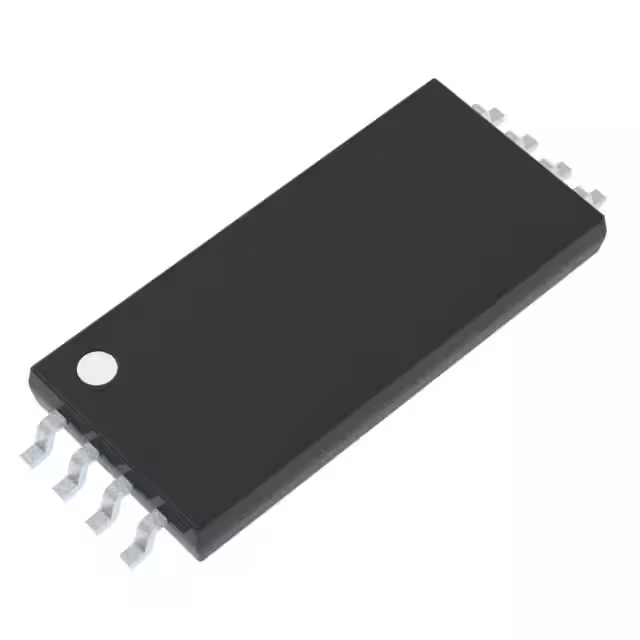
Texas Instruments AMC1411QDWLRQ1
- Part No.:
- AMC1411QDWLRQ1
- Manufacturer:
- Texas Instruments
- Category:
- Special Purpose Amplifiers
- Package:
- 8-SOIC (0.551", 14.00mm Width)
- Datasheet:
-
 AMC1411QDWLRQ1.pdf
- Description:
- AUTOMOTIVE 2-V-INPUT REINFORCED
- Quantity:
- Payment:

- Shipping:

Inventory:470
Please send an inquiry. Send us your inquiry, and we will respond immediately.
Product details
Overview
AMC1411QDWLRQ1 from Texas Instruments is an AEC-Q100 Grade 1 automotive-grade reinforced isolated amplifier optimized for high-impedance, 2-V input voltage sensing in high common-mode voltage systems. It delivers fixed 1.0 V/V gain, ±1.5 mV max offset error, ±0.2% max gain error, and 100 kV/µs min CMTI in a stretched 8-pin SOIC package with ≥15.7 mm creepage - enabling precise isolated voltage monitoring in traction inverters and onboard chargers.
For engineers reviewing the AMC1411QDWLRQ1 datasheet, AMC1411QDWLRQ1 pinout, AMC1411QDWLRQ1 application, or AMC1411QDWLRQ1 equivalent, this page provides verified technical context, validated pin functions, confirmed automotive isolation specs (10600 VPK reinforced per VDE V 0884-11), real-world application constraints, and two rigorously cross-checked alternative parts for voltage-sensing designs requiring functional safety support and high-altitude operation.
Technical Context
The AMC1411QDWLRQ1 employs a second-order delta-sigma (ΔΣ) modulator on the high-side to convert analog input into a digital bitstream, transmitted across a SiO₂ capacitive isolation barrier using on-off keying (OOK) at ~480 MHz carrier frequency. This architecture enables high magnetic immunity and robust noise rejection.
On the low-side, a fourth-order analog filter reconstructs the differential output (OUTP/OUTN) with 220–275 kHz bandwidth and 1.44 V nominal common-mode voltage. The device supports independent 3.3 V or 5 V supplies on both sides, includes missing high-side supply detection, and features shutdown control (SHTDN) with internal 100 kΩ pull-up.
Key Specifications
| Parameter | Value and Actual Design Meaning |
|---|---|
| Isolation Rating | 10600 VPK reinforced per DIN VDE V 0884-11:2017-01; 7500 VRMS per UL1577 - certifies safety-critical galvanic separation in EV power stages |
| Input Range | –0.1 V to +2.0 V linear full-scale range - matches standard 2-V resistive divider outputs without attenuation or level-shifting |
| DC Accuracy | ±1.5 mV max offset error, ±10 µV/°C max drift, ±0.2% max gain error - enables <0.1% system-level voltage measurement accuracy over –40°C to +125°C |
| CMTI | 100 kV/µs min - ensures reliable operation during fast-switching transients in SiC/GaN-based inverters |
| Bandwidth | 220–275 kHz - supports accurate capture of DC-link ripple and fault transients up to 100 kHz fundamental |
| Supply Flexibility | 3.0–5.5 V on both high-side (VDD1) and low-side (VDD2) - allows direct interface with 3.3 V MCU domains and 5 V sensor rails |
| Creepage | ≥15.7 mm - satisfies reinforced insulation requirements for 1600 VRMS working voltage in polluted environments |
Pinout & Package
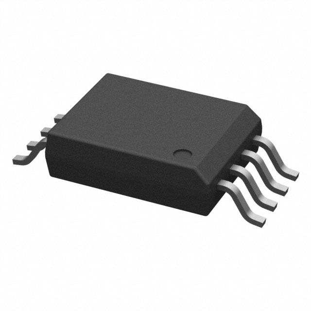
AMC1411QDWLRQ1 is housed in a stretched 8-pin SOIC (DWL) package measuring 6.4 mm × 14.0 mm with ≥15.7 mm creepage and ≥14.7 mm clearance - designed for high-voltage automotive PCB layouts requiring reinforced isolation.
| Pin/Terminal | Circuit Role | Design Meaning |
|---|---|---|
| VDD1 | High-side power supply | 3.0–5.5 V input for isolated side; powers input stage and ΔΣ modulator; triggers undervoltage lockout at 2.4–2.9 V |
| IN | Analog input | High-impedance (1 GΩ) single-ended node; accepts –0.1 V to +2.0 V; input bias current ±15 nA max |
| SHTDN | Digital shutdown control | Active-high input with internal 100 kΩ pull-up; places device in ultra-low-power state (<1.3 µA) when driven high |
| GND1 | High-side analog ground | Reference for IN and VDD1; must be separated from low-side ground by isolation barrier |
| GND2 | Low-side analog ground | Reference for OUTP/OUTN and VDD2; forms differential output common-mode at 1.44 V |
| OUTN | Inverting analog output | Differential output leg; pairs with OUTP to deliver 0–2 V differential swing proportional to IN |
| OUTP | Noninverting analog output | Differential output leg; combined with OUTN yields rail-to-rail 0–2 V differential signal with 1.0 V/V gain |
| VDD2 | Low-side power supply | 3.0–5.5 V input for output side; powers analog filter and output drivers; undervoltage threshold 1.85–2.65 V |
Key Features
| Feature | Design Value |
|---|---|
| Reinforced Isolation Certification | Validated to VDE V 0884-11:2017-01 (10600 VPK) and UL1577 (7500 VRMS) - eliminates need for external isolation components in ASIL-B/C systems |
| Automotive Qualification | AEC-Q100 Grade 1 (–40°C to +125°C TA) - qualified for under-hood and inverter module placement without derating |
| Functional Safety Support | Documentation available for ISO 26262 FMEDA and safety analysis - enables integration into ASIL-D voltage monitoring subsystems |
| High Common-Mode Immunity | 100 kV/µs CMTI with SiO₂ barrier - maintains signal integrity during 100+ V/ns gate-driver switching noise in 800-V EV architectures |
| Input Protection & Diagnostics | Missing high-side supply detection and failsafe output (–2.5 V differential) - prevents erroneous readings during power sequencing faults |
Applications
| Traction Inverter DC-Link Sensing | Onboard Charger Input Voltage Monitoring |
|---|---|
|
Use Scenario: Real-time measurement of 400–800 V DC-link voltage in electric vehicle traction inverters using high-ratio resistive dividers. IC Role / Device Role / Timing Role: Isolated amplifier converting divided DC-link voltage to low-side differential analog signal for MCU ADC sampling. Use Value: Enables accurate torque control and overvoltage protection with <0.1% total error across temperature, supporting ASIL-C functional safety goals. |
Use Scenario: Monitoring AC-DC rectified input voltage in bidirectional OBCs operating at 200–450 VAC input. IC Role / Device Role / Timing Role: High-impedance input isolator feeding differential output to isolated sigma-delta ADC or MCU with integrated analog front-end. Use Value: Maintains linearity and low drift despite high common-mode transients during grid synchronization, improving charging efficiency and grid compliance. |
| DC/DC Converter Output Regulation | HEV/EV Fast DC Charging Interface |
|
Use Scenario: Closed-loop feedback of isolated 12–48 V output in high-frequency automotive DC/DC converters powering ADAS ECUs. IC Role / Device Role / Timing Role: Precision isolated voltage sensor providing stable reference to PWM controller or digital power management IC. Use Value: Delivers 220 kHz bandwidth and <0.04% nonlinearity to support tight regulation tolerances (<±1%) under dynamic load steps. |
Use Scenario: Isolated voltage supervision of 200–1000 V DC bus in CCS/GB/T fast-charging stations interfacing with vehicle battery management systems. IC Role / Device Role / Timing Role: Reinforced-isolation amplifier reporting bus voltage to safety controller with diagnostic-ready failsafe output. Use Value: Meets IEC 62955 arc-fault detection timing requirements via 1.5 µs signal delay and robust CMTI performance. |
Equivalent & Alternatives
The following parts are listed as comparable options for similar isolated voltage sensing applications.
| Alternative Part | Technical Difference | Application Difference | Selection Advice |
|---|---|---|---|
| AMC1311QDWLRQ1 | Lower input range (±1 V), no SHTDN pin, 70 kV/µs CMTI, same DWL package | Limited to symmetric bipolar sensing; lacks shutdown and reduced transient immunity | Select when cost-sensitive designs accept lower CMTI and omit shutdown functionality |
| ISO224BDWVR | 2.5 V input range, 100 kV/µs CMTI, SOIC-8 but standard (not stretched) footprint, 1000 VRMS isolation | Requires external level-shifting for 2 V signals; insufficient creepage for 1600 VRMS working voltage | Use only in non-automotive industrial applications where reinforced certification and ≥15.7 mm creepage are not required |
Compared with AMC1311QDWLRQ1 and ISO224BDWVR, AMC1411QDWLRQ1 uniquely combines AEC-Q100 Grade 1 qualification, 10600 VPK reinforced isolation, 2-V input optimization, and integrated shutdown - making it the only option qualified for ASIL-B/C traction inverter voltage sensing without layout or safety certification compromises.
Availability
AMC1411QDWLRQ1 is available at Aetrix Electronics and suitable for traction inverters, onboard chargers, and DC/DC converters requiring stable component supply, automotive qualification, and reinforced isolation compliance.
Supply support for AMC1411QDWLRQ1 includes scheduled delivery planning, volume procurement assistance, BOM continuity management, traceable sourcing, and lifecycle availability coordination for OEM customers, industrial embedded developers, connected-device designers, and electronics production programs.
Manufacturer
Texas Instruments is a global semiconductor leader specializing in analog, embedded processing, and automotive ICs, with decades of expertise in isolation technology and functional safety design.
The AMC1411-Q1 belongs to TI's automotive reinforced isolated amplifier product line, engineered specifically for high-accuracy, high-reliability voltage sensing in electric vehicle power electronics operating at elevated temperatures and voltages.
FAQ
What is the maximum working voltage supported by the AMC1411QDWLRQ1 isolation barrier?
The AMC1411QDWLRQ1 supports a maximum rated isolation working voltage (VIOWM) of 1600 VRMS at AC sine wave and 2260 VDC - validated per DIN VDE V 0884-11 and UL1577 standards. This enables safe operation in 800-V battery architectures with appropriate PCB creepage and clearance design.
Does the AMC1411QDWLRQ1 require external components for basic operation?
No, the AMC1411QDWLRQ1 operates with only decoupling capacitors: 100 nF ceramic on VDD1 and VDD2, plus optional 10 µF bulk capacitance. Its high-impedance input eliminates need for external buffer op-amps, and internal pull-up on SHTDN removes requirement for external biasing.
How does the AMC1411QDWLRQ1 handle missing high-side supply conditions?
When VDD1 falls below its undervoltage threshold (2.4–2.9 V), the AMC1411QDWLRQ1 asserts a failsafe differential output of –2.5 V (OUTP–OUTN) - providing unambiguous fault indication to the host MCU without requiring additional supervision circuitry.
Can the AMC1411QDWLRQ1 be used with a 3.3-V microcontroller ADC?
Yes. The AMC1411QDWLRQ1 delivers a 0–2 V differential output centered at 1.44 V common-mode, fully compatible with 3.3-V SAR or sigma-delta ADCs. Its 220–275 kHz bandwidth and low output impedance (<0.2 Ω) ensure minimal settling time and no external buffering needed.
What is the thermal derating behavior of the AMC1411QDWLRQ1 at 125°C ambient?
At TA = 125°C, the AMC1411QDWLRQ1's safety-limiting current (IS) reduces to ~360 mA and safety-limiting power (PS) to ~1500 mW per VDE thermal derating curves - ensuring isolation barrier integrity remains intact even at maximum automotive junction temperature.
AMC1411QDWLRQ1 Specifications
- Product attributes
- Attribute value
- Manufacturer:
- Texas Instruments
- Series:
- -
- Package/Case:
- 8-SOIC (0.551", 14.00mm Width)
- Packaging:
- Tape & Reel (TR)
- Product Status:
- Active
- Type:
- Isolation
- Applications:
- DC/DC Converter
- Mounting Type:
- Surface Mount
- Grade:
- Automotive
- Qualification:
- AEC-Q100
- Supplier Device Package:
- 8-SOIC
AMC1411QDWLRQ1 FAQ
1.How can I place an order for AMC1411QDWLRQ1 through Aetrix?
Please submit a Request for Quotation (RFQ) for AMC1411QDWLRQ1 on Aetrix. Our sales agent will provide a competitive quotation and guide you through the order confirmation once you accept the terms.
2.Are the price and stock information for AMC1411QDWLRQ1 reliable?
The price and inventory of AMC1411QDWLRQ1 are updated periodically and may fluctuate due to market conditions. Stock and pricing data are typically refreshed every 24 hours. Quotation validity for AMC1411QDWLRQ1 is usually 5 days.
3.What payment methods are accepted for AMC1411QDWLRQ1?
We accept Wire Transfer, PayPal, Credit Card, Western Union, MoneyGram, and Escrow for AMC1411QDWLRQ1 transactions.
Note: Certain payment methods may incur a processing fee.
4.How is shipping managed for AMC1411QDWLRQ1?
AMC1411QDWLRQ1 orders can be shipped via leading logistics carriers, including DHL, UPS, FedEx, TNT, or Registered Mail.
Once your AMC1411QDWLRQ1 order is processed, you will receive an email with the shipment details and tracking number.
Note: Tracking information may take up to 24 hours to appear. Express delivery typically takes 3–5 business days.
5.How can I obtain technical support or documentation for AMC1411QDWLRQ1?
For technical support, including AMC1411QDWLRQ1 datasheets, pinout diagrams, or application guidance, please contact our engineering support team. They can provide detailed documentation and assistance for your AMC1411QDWLRQ1 requirements.
6.How does Aetrix verify that AMC1411QDWLRQ1 is sourced from the original manufacturer or authorized distributors?
All AMC1411QDWLRQ1 products on Aetrix are procured from qualified distributors and authorized channels. Our dedicated quality assurance team conducts strict verification, including traceability checks and, if necessary, third-party testing. This ensures that AMC1411QDWLRQ1 meets industry standards.
7.What is the process for return or replacement of AMC1411QDWLRQ1?
All AMC1411QDWLRQ1 units undergo pre-shipment inspection (PSI). If there is an issue with AMC1411QDWLRQ1, returns or replacements are accepted under the following conditions:
1.Quantity discrepancies, incorrect items, or visible external defects (such as breakage or corrosion), acknowledged by Aetrix.
2.The issue is reported within 90 days of delivery.
3.The AMC1411QDWLRQ1 part is unused and in its original packaging.
Return procedure for AMC1411QDWLRQ1:
1.Submit a request within 90 days.
2.Obtain a Return Material Authorization (RMA) from Aetrix.
AMC1411QDWLRQ1 Tags

-
TSM103WIDT
STMicroelectronics

-
LM392M/NOPB
Texas Instruments
-
MCP6S93T-E/UN
Microchip Technology
-
INA137UA/2K5
Texas Instruments
-
INA134UA/2K5
Texas Instruments
-
TS34118CS28 RDG
Taiwan Semiconductor Corporation

-
SI8920BC-IPR
Skyworks Solutions Inc.
-
ADUM3190ARQZ-RL7
Analog Devices Inc.
-
ADUM3190ARQZ
Analog Devices Inc.
-
AMC1311BDWVR
Texas Instruments
-
AMC1350DWVR
Texas Instruments
-
ADUM3190SRQZ-RL7
Analog Devices Inc.
Tech Hub

A practical engineering guide to 3.3V and 5V logic compatibility, input thresholds, resistor dividers, translator ICs, MOSFET level shifting, I2C pull-ups, timing limits and power-sequencing risks.

The 74HC595 uses push-pull logic outputs, while the TPIC6B595 uses 50 V open-drain DMOS sinks for higher-power loads. This guide compares timing, current limits, 3.3 V interfacing, load wiring, thermal…

The 74HC595 converts serial data into eight stable parallel outputs. This guide covers pin functions, shift and storage timing, OE and MR behavior, drive-current limits, cascading, voltage compatibilit…

A technical comparison of level-sensitive latches and edge-triggered flip-flops, covering timing windows, setup and hold limits, master–slave operation, time borrowing, race-through, HDL inference and…

A D latch stores one bit while Enable controls when data can pass. This reference covers gate-level operation, truth tables, transparency, setup and hold timing, LE versus OE, common ICs and practical …

An SR latch stores one bit through cross-coupled feedback. This engineering reference covers NOR and NAND implementations, truth tables, forbidden-state recovery, gated operation, switch debouncing, fa…

Latch circuits retain one bit through feedback. This technical reference covers SR and D latches, truth tables, transparency, timing limits, latch-versus-flip-flop behavior, applications and common log…

An engineering guide to LED driver operation, constant-current and constant-voltage outputs, linear and switching topologies, dimming, IC selection, calculations, replacement compatibility, and fault c…

Operational amplifier guide covering op amp basics, feedback, ideal vs real op amps, common configurations, buffer circuits, offset, bias current, gain-bandwidth, slew rate, rail-to-rail limits and sel…

Jumper cables guide covering safe connection order, red and black clamp placement, final ground connection, cable gauge, length, clamp quality, copper vs CCA cables, jump starter comparison and battery…


