
 My Inquiry
 My Account


Asahi Kasei Microdevices/AKM AP1037AER
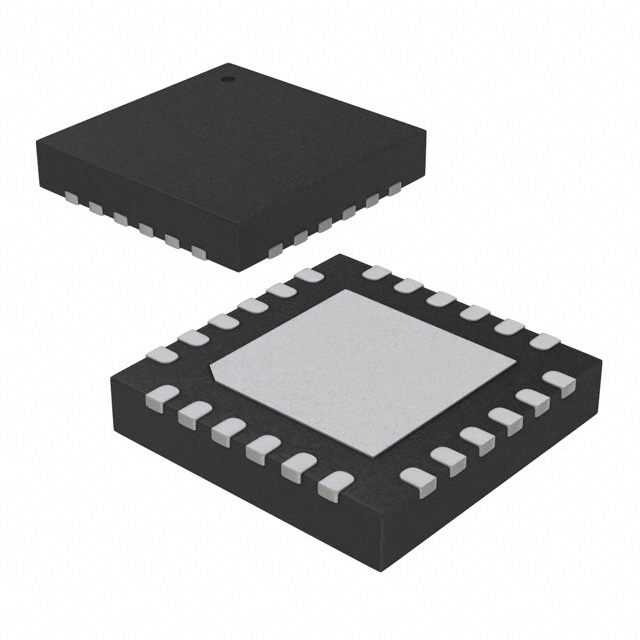
- Part No.:
- AP1037AER
- Manufacturer:
- Asahi Kasei Microdevices/AKM
- Category:
- Motor Drivers, Controllers
- Package:
- 24-WFQFN Exposed Pad
- Datasheet:
-
 AP1037AER.pdf
- Description:
- IC MTR DRVR BIPOLAR 8-35V 24QFN
- Quantity:
- Payment:

- Shipping:

Inventory:358
Please send an inquiry. Send us your inquiry, and we will respond immediately.
Product details
Overview
AP1037AER from Asahi Kasei Microdevices (AKM) is a bipolar stepper motor driver IC with integrated PWM current control, Active Decay Control, and single-supply operation. It supports 8–35 V motor supply voltage, delivers up to 1.5 A continuous output current per H-bridge, features 24-pin QFN (4.0 mm × 4.0 mm) packaging, and enables microstepping down to 1/8-step for precision motion control in compact MFPs and robotics.
For engineers reviewing the AP1037AER datasheet, AP1037AER pinout, AP1037AER application, or AP1037AER equivalent, key selection considerations include its 1.5 A current rating, 24-pin QFN thermal performance, clock-in interface compatibility with 3.3 V/5 V logic, selectable 39 kHz / 77 kHz chopper frequency, and built-in protection circuits (UVLO, TSD, OCP) for robust motor drive implementation.
Technical Context
The AP1037AER implements AKM's proprietary Active Decay Control architecture to dynamically select slow decay, fast decay, or pre-fast decay modes based on current waveform phase-reducing ripple and improving torque linearity. Its dual H-bridge output stage integrates gate drivers, charge pump, and internal regulator, enabling full motor control from a single VM rail without auxiliary supplies.
Microstepping is configured via MODE1/MODE2 pins (supporting 2-phase, 1-2-phase, W1-2-phase, and 2W1-2-phase excitation), while STEP/DIR inputs provide simple clock-and-direction sequencing. Protection logic includes latch-off overcurrent detection (with recovery via SLEEPB/RESETB or VM cycle), automatic thermal shutdown (175 °C trip, 145 °C hysteresis), and UVLO (6.35 V threshold).
Key Specifications
| Parameter | Value and Actual Design Meaning |
|---|---|
| Motor Supply Voltage | 8.0–35.0 V - Enables direct use with common industrial DC rails (e.g., 12 V, 24 V) without external regulators. |
| Max Continuous Output Current | 1.5 A per H-bridge - Supports NEMA 17–23 class stepper motors at full torque in compact designs. |
| On-Resistance (HS+LS) | 0.95 Ω (typ.) - Limits conduction loss to ≤2.14 W at 1.5 A, critical for thermal management in 24-pin QFN. |
| PWM Chopper Frequency | 39 kHz (FS=L) or 77 kHz (FS=H) - Higher frequency reduces audible noise and allows smaller external filter components. |
| Operating Temperature Range | −30 °C to +85 °C - Validated for industrial environments including ATM, vending, and POS equipment enclosures. |
| Input Logic Compatibility | 3.3 V / 5 V tolerant - Direct interfacing with MCU GPIOs without level-shifting circuitry. |
| Current Sense Accuracy | ±5 % at 100 % load - Ensures precise torque control across microstep positions with minimal calibration overhead. |
Pinout & Package
AP1037AER is housed in a thermally enhanced 24-pin QFN package (4.0 mm × 4.0 mm, 0.5 mm pitch) with an exposed pad for PCB-level heat dissipation. The package complies with JEDEC MS-012 standards and requires connection of the exposed pad to system ground for optimal thermal performance (θJA = 40 °C/W on 4-layer board).
| Pin/Terminal | Circuit Role | Design Meaning |
|---|---|---|
| OUT1A, OUT1B, OUT2A, OUT2B | H-bridge output terminals | Drive bipolar stepper coil pairs; support bidirectional current flow with integrated high-/low-side MOSFETs. |
| IS1, IS2 | Current sense inputs | Connect to low-side sense resistors (e.g., 0.24 Ω) to enable closed-loop PWM current regulation. |
| STEP, DIR, MODE1, MODE2 | Digital control inputs | Accept standard CMOS logic; configure step advance, rotation direction, and microstep resolution (1/8-step max). |
| ENABLEB, SLEEPB, RESETB | System control inputs | Enable/disable outputs, enter ultra-low-power sleep mode (<10 µA VM consumption), or reset to home position. |
| VREF | Reference voltage input | Sets target current via external DAC or resistor divider; ILOAD(100%) = (VREF/8)/RIS. |
| VM1, VM2 | Motor power supply inputs | Split VM connections reduce trace inductance and improve current sharing between H-bridges. |
| CH, CL, VG, VDC | Charge pump & regulator nodes | Support internal gate drive and logic supply generation from VM alone-no auxiliary supply required. |
| GND, Exposed Pad | Ground reference & thermal path | Must be connected to solid PCB ground plane; exposed pad is electrically and thermally tied to GND. |
Key Features
| Feature | Design Value |
|---|---|
| Active Decay Control | Automatically selects optimal decay mode per step transition-reduces current distortion and improves low-speed torque stability. |
| Single-Supply Operation | Derives all internal voltages (gate drive, logic, regulator) from VM (8–35 V); eliminates need for separate 5 V or 3.3 V bias rails. |
| Spike Noise Blanking | Hardware blanking (1.3–2.6 µs) during charge mode prevents false OCP triggering-enables reliable operation without external RC filters. |
| Power Saving Function | VM quiescent current <10 µA in sleep mode-extends uptime in battery-backed or energy-conscious applications like portable scanners. |
| Built-in Protection Suite | Integrated UVLO (6.35 V), TSD (175 °C trip), and OCP (2.0–7.5 A trip) with automatic or latch-off behavior per fault condition. |
Applications
| Multi-Function Printers (MFP) | ATM & Vending Machines |
|---|---|
Use Scenario: Precise paper feed, scanner carriage movement, and document stacking in compact office MFPs. IC Role / Device Role / Timing Role: Stepper motor driver executing 1/8-step microstepping sequences under MCU clock-in control with real-time current regulation. Use Value: Reduces mechanical vibration and acoustic noise while maintaining positional accuracy across variable load conditions. |
Use Scenario: Bill dispensing, card ejection, and cash cassette positioning in space-constrained ATM and vending machine chassis. IC Role / Device Role / Timing Role: Bipolar stepper driver managing bidirectional motion with forward/reverse direction control and home-position reset via RESETB. Use Value: Enables deterministic start-up and error recovery through integrated UVLO and sleep-mode reset-critical for unattended operation. |
| Industrial Robotics (Gripper/Actuator) | Point-of-Sale (POS) Terminals |
Use Scenario: Low-inertia joint actuation and end-effector positioning in collaborative robotic arms and pick-and-place modules. IC Role / Device Role / Timing Role: High-efficiency motor driver delivering 1.5 A peak current with Active Decay Control to minimize torque ripple at sub-100 RPM speeds. Use Value: Improves motion smoothness and repeatability without requiring external current-sense amplifiers or decay-mode configuration logic. |
Use Scenario: Receipt printer head translation, cash drawer actuation, and barcode scanner sled movement in retail POS systems. IC Role / Device Role / Timing Role: Compact QFN stepper driver supporting 3.3 V MCU interfaces and operating reliably across −30 °C to +85 °C ambient range. Use Value: Eliminates need for level shifters or heatsinks-reducing BOM count and PCB area in cost-sensitive, high-volume consumer electronics. |
Equivalent & Alternatives
The following parts are listed as comparable options for similar stepper motor driver applications.
| Alternative Part | Technical Difference | Application Difference | Selection Advice |
|---|---|---|---|
| AP1037AEN | 32-pin QFN (5.0 mm × 5.0 mm); identical electrical specs and pin-compatible with AP1037AER except for larger footprint and higher thermal dissipation (PD = 3.9 W @ 25 °C). | Preferred where higher continuous current derating or improved thermal margin is required in less space-constrained designs. | Select AP1037AEN when board layout allows larger package and thermal design targets exceed 1.5 A sustained load at >60 °C ambient. |
| AP1034AER | Same 24-pin QFN footprint; rated for 2.0 A continuous output current; otherwise identical feature set and pinout. | Suitable for driving higher-torque NEMA 23 motors or applications requiring headroom beyond 1.5 A without changing PCB layout. | Choose AP1034AER if motor peak current demand exceeds 1.5 A but mechanical envelope and control interface must remain unchanged. |
Compared with AP1037AEN and AP1034AER, the AP1037AER offers the optimal balance of thermal performance, microstepping fidelity, and space efficiency for mid-power stepper applications-delivering 1.5 A in the smallest possible QFN form factor while retaining full protection and decay control functionality.
Availability
AP1037AER is available at Aetrix Electronics and suitable for multi-function printers, ATM mechanisms, and industrial robotics requiring stable component supply, long-term lifecycle assurance, and consistent parametric performance across production batches.
Supply support for AP1037AER includes scheduled delivery planning, volume procurement assistance, BOM continuity management, traceable sourcing, and lifecycle availability coordination for OEM customers, industrial embedded developers, connected-device designers, and electronics production programs.
Manufacturer
Asahi Kasei Microdevices (AKM) is a Japanese semiconductor company specializing in analog, mixed-signal, and sensor ICs, with core expertise in precision motor control, audio, and magnetic sensing technologies.
The AP1037 series was designed specifically for compact, high-efficiency bipolar stepper motor drive in industrial automation and office equipment-emphasizing integration, thermal resilience, and ease of MCU interface.
FAQ
What is the maximum motor supply voltage supported by the AP1037AER?
The AP1037AER supports a motor supply voltage range of 8.0 V to 35.0 V. This allows direct operation from common industrial DC rails such as 12 V or 24 V without intermediate regulation. Exceeding 35.0 V may cause permanent damage, as specified in the Absolute Maximum Ratings table.
Does the AP1037AER require an external power supply for its logic circuitry?
No, the AP1037AER does not require an external logic supply. It integrates an internal regulator that derives all control circuit voltages-including gate drive and logic-directly from the VM rail. This single-supply operation simplifies system design and reduces BOM count.
How does the Active Decay Control in the AP1037AER improve motor performance?
The AP1037AER's Active Decay Control dynamically selects between slow, fast, and pre-fast decay modes during each PWM cycle based on current waveform behavior. This minimizes current ripple, improves torque linearity at low speeds, and enhances positional accuracy-especially during microstepping transitions.
What protection features are built into the AP1037AER?
The AP1037AER includes Under Voltage Lockout (UVLO), Thermal Shutdown (TSD), and Over Current Protection (OCP). UVLO disables outputs below 6.35 V; TSD trips at 175 °C and recovers automatically at 145 °C; OCP latches off outputs upon overcurrent detection and requires SLEEPB, RESETB, or VM cycling to reset.
Can the AP1037AER drive stepper motors in 1/8-step mode?
Yes, the AP1037AER supports 1/8-step microstepping via the 2W1-2 Phase excitation mode, selected using MODE1 and MODE2 pins. This mode provides 32 microsteps per full step, enabling smoother motion and reduced resonance compared to full- or half-step operation.
AP1037AER Specifications
- Product attributes
- Attribute value
- Manufacturer:
- Asahi Kasei Microdevices/AKM
- Series:
- -
- Package/Case:
- 24-WFQFN Exposed Pad
- Packaging:
- Tape & Reel (TR)
- Product Status:
- Obsolete
- Motor Type - Stepper:
- Bipolar
- Motor Type - AC, DC:
- -
- Function:
- Driver - Fully Integrated, Control and Power Stage
- Output Configuration:
- Half Bridge (4)
- Interface:
- Logic
- Technology:
- Power MOSFET
- Step Resolution:
- 1, 1/2, 1/4, 1/8
- Applications:
- General Purpose
- Current - Output:
- 1.5A
- Voltage - Supply:
- 8V ~ 35V
- Voltage - Load:
- 8V ~ 35V
- Operating Temperature:
- -30°C ~ 150°C (TJ)
- Grade:
- -
- Qualification:
- -
- Mounting Type:
- Surface Mount
- Supplier Device Package:
- 24-QFN (4x4)
AP1037AER FAQ
1.How can I place an order for AP1037AER through Aetrix?
Please submit a Request for Quotation (RFQ) for AP1037AER on Aetrix. Our sales agent will provide a competitive quotation and guide you through the order confirmation once you accept the terms.
2.Are the price and stock information for AP1037AER reliable?
The price and inventory of AP1037AER are updated periodically and may fluctuate due to market conditions. Stock and pricing data are typically refreshed every 24 hours. Quotation validity for AP1037AER is usually 5 days.
3.What payment methods are accepted for AP1037AER?
We accept Wire Transfer, PayPal, Credit Card, Western Union, MoneyGram, and Escrow for AP1037AER transactions.
Note: Certain payment methods may incur a processing fee.
4.How is shipping managed for AP1037AER?
AP1037AER orders can be shipped via leading logistics carriers, including DHL, UPS, FedEx, TNT, or Registered Mail.
Once your AP1037AER order is processed, you will receive an email with the shipment details and tracking number.
Note: Tracking information may take up to 24 hours to appear. Express delivery typically takes 3–5 business days.
5.How can I obtain technical support or documentation for AP1037AER?
For technical support, including AP1037AER datasheets, pinout diagrams, or application guidance, please contact our engineering support team. They can provide detailed documentation and assistance for your AP1037AER requirements.
6.How does Aetrix verify that AP1037AER is sourced from the original manufacturer or authorized distributors?
All AP1037AER products on Aetrix are procured from qualified distributors and authorized channels. Our dedicated quality assurance team conducts strict verification, including traceability checks and, if necessary, third-party testing. This ensures that AP1037AER meets industry standards.
7.What is the process for return or replacement of AP1037AER?
All AP1037AER units undergo pre-shipment inspection (PSI). If there is an issue with AP1037AER, returns or replacements are accepted under the following conditions:
1.Quantity discrepancies, incorrect items, or visible external defects (such as breakage or corrosion), acknowledged by Aetrix.
2.The issue is reported within 90 days of delivery.
3.The AP1037AER part is unused and in its original packaging.
Return procedure for AP1037AER:
1.Submit a request within 90 days.
2.Obtain a Return Material Authorization (RMA) from Aetrix.
AP1037AER Tags

-
DRV2603RUNR
Texas Instruments

-
DRV8837CDSGR
Texas Instruments

-
DRV8837DSGR
Texas Instruments
-
DRV8838DSGR
Texas Instruments

-
DRV8839DSSR
Texas Instruments

-
EMC2301-1-ACZL-TR
Microchip Technology
-
DRV8231ADSGR
Texas Instruments

-
EMC2302-2-AIZL-TR
Microchip Technology

-
DRV8800PWPR
Texas Instruments
-
DRV8835DSSR
Texas Instruments

-
EMC2303-1-KP-TR
Microchip Technology

-
DRV8876PWPR
Texas Instruments
Tech Hub

A practical engineering and sourcing framework covering lifecycle verification, lifetime-buy calculations, replacement qualification, supplier checks and counterfeit-risk controls.

TTL and CMOS logic families differ in thresholds, loading, output drive, power and timing. This engineering guide compares 74HC and 74HCT, calculates noise margins and checks 3.3 V/5 V compatibility.

A practical engineering guide to 3.3V and 5V logic compatibility, input thresholds, resistor dividers, translator ICs, MOSFET level shifting, I2C pull-ups, timing limits and power-sequencing risks.

The 74HC595 uses push-pull logic outputs, while the TPIC6B595 uses 50 V open-drain DMOS sinks for higher-power loads. This guide compares timing, current limits, 3.3 V interfacing, load wiring, thermal…

The 74HC595 converts serial data into eight stable parallel outputs. This guide covers pin functions, shift and storage timing, OE and MR behavior, drive-current limits, cascading, voltage compatibilit…

A technical comparison of level-sensitive latches and edge-triggered flip-flops, covering timing windows, setup and hold limits, master–slave operation, time borrowing, race-through, HDL inference and…

A D latch stores one bit while Enable controls when data can pass. This reference covers gate-level operation, truth tables, transparency, setup and hold timing, LE versus OE, common ICs and practical …

An SR latch stores one bit through cross-coupled feedback. This engineering reference covers NOR and NAND implementations, truth tables, forbidden-state recovery, gated operation, switch debouncing, fa…

Latch circuits retain one bit through feedback. This technical reference covers SR and D latches, truth tables, transparency, timing limits, latch-versus-flip-flop behavior, applications and common log…

An engineering guide to LED driver operation, constant-current and constant-voltage outputs, linear and switching topologies, dimming, IC selection, calculations, replacement compatibility, and fault c…


