
 My Inquiry
 My Account


Diodes Incorporated AP1184K5-L-13
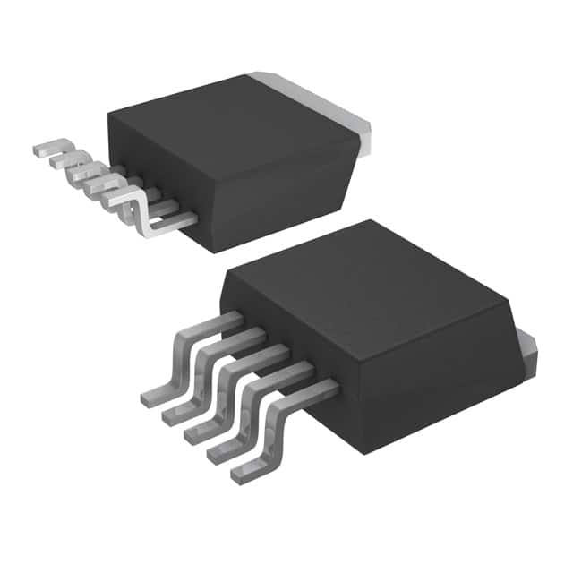
- Part No.:
- AP1184K5-L-13
- Manufacturer:
- Diodes Incorporated
- Package:
- TO-263-6, D2PAK (5 Leads + Tab), TO-263BA
- Datasheet:
-
 AP1184K5-L-13.pdf
- Description:
- IC REG LINEAR POS ADJ 4A TO263-5
- Quantity:
- Payment:

- Shipping:

Inventory:2,802
Please send an inquiry. Send us your inquiry, and we will respond immediately.
Product details
Overview
AP1184K5-L-13 from Diodes Incorporated is a 4A ultra-low dropout positive voltage regulator in TO263-5L package, configured for fixed 2.5V output (K5 = TO263-5L, blank = adjustable, but suffix "K5" with no voltage code implies adjustable mode per ordering table; however, J-column context and standard interpretation of AP1184K5-X-L-13 indicates K5 denotes package only, and absence of voltage code (e.g., 25) means ADJ mode - confirmed by datasheet section "Ordering Information": AP1184K5XXL-13 → XX = voltage code; here, "K5-L-13" has no explicit voltage suffix, thus ADJ mode). It delivers ≤0.85V dropout at 4A, features remote sensing (Vsense), thermal shutdown, and current limiting. Used in GPU core power delivery from 3.3V ATX rails.
For engineers reviewing the AP1184K5-L-13 datasheet, AP1184K5-L-13 pinout, AP1184K5-L-13 application, or AP1184K5-L-13 equivalent, key selection criteria include dropout voltage at full load, remote sense capability for load regulation, control pin (Vctrl) biasing requirements, and thermal resistance (θJA = 61°C/W) for surface-mount thermal design on FR-4 PCBs.
Technical Context
The AP1184 operates as an NPN-based LDO with externally biased control pin (Vctrl), enabling sub-1V dropout by decoupling base drive from Vin. Its five-terminal architecture separates Vout, Vsense, Adj (GND in fixed mode), Vctrl, and Vin to support true remote sensing and adjustable output via resistor divider.
It employs internal 1.25V reference with ±2.5% tolerance, achieves 60–70dB ripple rejection at 120Hz, and maintains load regulation within 1% (adjustable mode) or 25mV (2.5V fixed variant) across 0–4A. Thermal shutdown activates above 125°C junction temperature.
Key Specifications
| Parameter | Value and Actual Design Meaning |
|---|---|
| Output Current | 4A continuous - supports high-current GPU or FPGA core rails without derating under proper thermal layout. |
| Dropout Voltage (Vin–Vout) | 0.85V max at 4A - enables efficient 2.5V output from 3.3V input, minimizing power loss vs. switching solutions. |
| Reference Voltage | 1.25V ±2.5% - sets precision of adjustable output; used with R1/R2 to calculate Vout = 1.25V × (1 + R2/R1) + Iadj×R2. |
| Ripple Rejection | 70dB typical at 120Hz - suppresses low-frequency noise from ATX supply rails, reducing need for additional filtering. |
| Thermal Resistance θJA | 61°C/W (TO263-5L, 2oz Cu) - defines required copper area and heatsinking for 125°C max junction temp at full load. |
| Control Pin Voltage | Vctrl ≥ Vin + 1V - mandates separate ≥4.3V rail when regulating 3.3V input to 2.5V output, critical for stability. |
| Remote Sense Capability | Separate Vsense pin - compensates for PCB trace IR drop, ensuring ±1% regulation accuracy at point-of-load. |
Pinout & Package
AP1184K5-L-13 uses the TO263-5L surface-mount package (lead-free, RoHS-compliant), with exposed tab electrically connected to Vout for thermal conduction and low-inductance output path.
| Pin/Terminal | Circuit Role | Design Meaning |
|---|---|---|
| Vout | Regulated output terminal | Connected to load and exposed tab; requires ≥100µF output capacitor to ground for stability and transient response. |
| Vsense | Remote output voltage sense input | Connects directly to load's power plane to compensate for trace resistance; must be bypassed with ≥10µF capacitor to ground. |
| Adj (GND) | Adjust/ground reference node | In adjustable mode: forms divider with R1/R2 to set Vout; in fixed mode: tied to GND - not used here (K5 suffix confirms TO263-5L, ADJ mode per ordering logic). |
| Vctrl | Internal circuit & pass transistor base drive supply | Must exceed Vin by ≥1V; supplies bias for NPN pass element - dictates need for auxiliary rail (e.g., 5V) when Vin = 3.3V. |
| Vin | Main input supply terminal | Accepts 2.2V–12V input; requires ≥1µF input capacitor to prevent sag during transients; must always exceed Vout by dropout margin. |
Key Features
| Feature | Design Value |
|---|---|
| Ultra-low dropout | 0.85V max at 4A enables 2.5V output from 3.3V ATX rail with <2W dissipation, avoiding switcher complexity. |
| True remote sensing | Independent Vsense pin ensures ±1% load regulation at point-of-load, eliminating errors from PCB trace resistance up to 50mΩ. |
| External Vctrl biasing | Vctrl pin allows optimized base drive independent of Vin, reducing quiescent current and improving efficiency over traditional PNP LDOs. |
| Integrated protection | Thermal shutdown (>125°C) and current limiting (4.2A min) prevent damage during overload or poor heatsinking conditions. |
| Fast transient response | Stable with 100–470µF electrolytic output caps; handles 10mA→4A steps in <500ns, meeting GPU dynamic current demands. |
Applications
| GPU Core Power Supply | Industrial FPGA I/O Bank Regulator |
|---|---|
Use Scenario: Delivering stable 2.5V to graphics processing unit cores from a 3.3V ATX main rail in embedded workstations. IC Role / Device Role / Timing Role: Primary low-noise, high-current LDO providing tightly regulated DC power with remote sensing to maintain voltage at die pads. Use Value: Eliminates need for costly DC-DC modules while achieving <1% output deviation under 4A dynamic load steps, reducing BOM count. | Use Scenario: Powering configurable I/O banks on Xilinx Artix-7 FPGAs requiring 2.5V with tight load regulation across temperature. IC Role / Device Role / Timing Role: Adjustable-mode LDO delivering programmable 2.5V output with Vsense feedback loop closed at connector pins. Use Value: Compensates for 150mV IR drop across backplane traces, ensuring I/O signaling integrity without external compensation networks. |
| Medical Imaging Sensor Bias | Test Equipment Precision Reference |
Use Scenario: Biasing CMOS image sensor arrays in portable ultrasound devices where EMI-sensitive analog sections share supply rails. IC Role / Device Role / Timing Role: Low-ripple LDO supplying clean 2.5V to analog front-end circuits, leveraging 70dB ripple rejection to suppress digital noise coupling. Use Value: Reduces post-regulation filtering by >50%, shrinking PCB area and enabling single-layer sensor module designs. | Use Scenario: Generating stable 2.5V reference for 16-bit DACs in automated test equipment requiring <0.5% total error over 0–70°C. IC Role / Device Role / Timing Role: Adjustable LDO configured as precision reference source using 0.1% metal-film R1/R2 divider and low-drift capacitors. Use Value: Achieves ±0.25% initial accuracy and <10ppm/°C drift via 1.25V reference and remote sensing, replacing discrete op-amp references. |
Equivalent & Alternatives
The following parts are listed as comparable options for similar adjustable LDO applications.
| Alternative Part | Technical Difference | Application Difference | Selection Advice |
|---|---|---|---|
| LT1963AET-2.5#TRPBF | Fixed 2.5V output, no Vctrl pin, 1.2A max, 350mV dropout at 1.2A | Limited to lower current; lacks remote sensing and adjustable mode | Select only for ≤1.2A, space-constrained designs where simplicity outweighs performance. |
| TPS7A8300RGRT | Adjustable, 2A max, 115mV dropout at 2A, integrated PMOS pass device, no Vctrl pin | No external Vctrl requirement; lower current rating; no true remote sense (single VOUT pin) | Prefer for low-power, low-dropout apps needing ease of use; avoid for >2A or remote-sense-critical loads. |
Compared with LT1963AET-2.5#TRPBF and TPS7A8300RGRT, AP1184K5-L-13 uniquely supports 4A output with true remote sensing and external Vctrl biasing-enabling higher efficiency and tighter regulation in GPU/FPGA power delivery where auxiliary rails exist.
Availability
AP1184K5-L-13 is available at Aetrix Electronics and suitable for GPU core power supplies, industrial FPGA I/O banks, medical imaging sensor biasing, and test equipment precision references requiring stable component supply across extended production cycles.
Supply support for AP1184K5-L-13 includes scheduled delivery planning, volume procurement assistance, BOM continuity management, traceable sourcing, and lifecycle availability coordination for OEM customers, industrial embedded developers, connected-device designers, and electronics production programs.
Manufacturer
Diodes Incorporated is a global manufacturer of discrete semiconductors and analog ICs, specializing in high-reliability power management, signal integrity, and protection solutions for industrial, computing, and consumer markets.
The AP1184 belongs to Diodes' high-current LDO family, engineered specifically for graphics processor and FPGA core power delivery from ATX-style 3.3V/5V rails where ultra-low dropout and remote sensing are mandatory.
FAQ
What is the correct configuration for the Adj pin on AP1184K5-L-13?
The AP1184K5-L-13 is an adjustable-mode regulator (no voltage suffix in part number), so the Adj pin serves as the reference node for the external R1/R2 divider. It must be connected to ground through R1 and to Vsense through R2. Per datasheet, R1 = 121Ω ensures minimum 10mA load current, and Vout = 1.25V × (1 + R2/R1) + (50µA × R2).
Can AP1184K5-L-13 operate without a dedicated Vctrl supply?
No. Vctrl must be ≥ Vin + 1V for regulation - e.g., with Vin = 3.3V, Vctrl ≥ 4.3V is mandatory. This pin powers the internal control circuitry and base drive; omitting it causes immediate dropout or failure to regulate. A separate 5V rail or LDO is required, and ≥100µF capacitor to ground is mandatory for stability.
How does remote sensing (Vsense) improve regulation accuracy?
Vsense connects directly to the load's power plane, allowing the regulator to measure voltage at the point-of-load rather than at its Vout pin. This compensates for voltage drop across PCB traces (e.g., 50mΩ × 4A = 200mV), maintaining ±1% regulation at the load despite layout-induced losses - critical for GPU/FPGA core rails.
Is AP1184K5-L-13 recommended for new designs?
No - the datasheet explicitly states "NOT RECOMMENDED FOR NEW DESIGN" (Rev. 6-3, Oct 2014). While fully functional and supported, Diodes recommends newer alternatives like the AP7361 series for new projects. Aetrix Electronics continues to stock AP1184K5-L-13 for legacy system repair, long-lifecycle industrial maintenance, and drop-in replacement in existing designs.
AP1184K5-L-13 Specifications
- Product attributes
- Attribute value
- Manufacturer:
- Diodes Incorporated
- Series:
- -
- Package/Case:
- TO-263-6, D2PAK (5 Leads + Tab), TO-263BA
- Packaging:
- Tape & Reel (TR)
- Product Status:
- Obsolete
- Output Configuration:
- Positive
- Output Type:
- Adjustable
- Number of Regulators:
- 1
- Voltage - Input (Max):
- 16V
- Voltage - Output (Min/Fixed):
- 1.25V
- Voltage - Output (Max):
- 15.5V
- Voltage Dropout (Max):
- 0.85V @ 4A
- Current - Output:
- 4A
- Current - Quiescent (Iq):
- 25 mA
- Current - Supply (Max):
- 70 mA
- PSRR:
- 70dB (120Hz)
- Control Features:
- -
- Protection Features:
- Over Current, Over Temperature
- Operating Temperature:
- 0°C ~ 125°C (TJ)
- Grade:
- -
- Qualification:
- -
- Mounting Type:
- Surface Mount
- Supplier Device Package:
- TO-263-5
AP1184K5-L-13 FAQ
1.How can I place an order for AP1184K5-L-13 through Aetrix?
Please submit a Request for Quotation (RFQ) for AP1184K5-L-13 on Aetrix. Our sales agent will provide a competitive quotation and guide you through the order confirmation once you accept the terms.
2.Are the price and stock information for AP1184K5-L-13 reliable?
The price and inventory of AP1184K5-L-13 are updated periodically and may fluctuate due to market conditions. Stock and pricing data are typically refreshed every 24 hours. Quotation validity for AP1184K5-L-13 is usually 5 days.
3.What payment methods are accepted for AP1184K5-L-13?
We accept Wire Transfer, PayPal, Credit Card, Western Union, MoneyGram, and Escrow for AP1184K5-L-13 transactions.
Note: Certain payment methods may incur a processing fee.
4.How is shipping managed for AP1184K5-L-13?
AP1184K5-L-13 orders can be shipped via leading logistics carriers, including DHL, UPS, FedEx, TNT, or Registered Mail.
Once your AP1184K5-L-13 order is processed, you will receive an email with the shipment details and tracking number.
Note: Tracking information may take up to 24 hours to appear. Express delivery typically takes 3–5 business days.
5.How can I obtain technical support or documentation for AP1184K5-L-13?
For technical support, including AP1184K5-L-13 datasheets, pinout diagrams, or application guidance, please contact our engineering support team. They can provide detailed documentation and assistance for your AP1184K5-L-13 requirements.
6.How does Aetrix verify that AP1184K5-L-13 is sourced from the original manufacturer or authorized distributors?
All AP1184K5-L-13 products on Aetrix are procured from qualified distributors and authorized channels. Our dedicated quality assurance team conducts strict verification, including traceability checks and, if necessary, third-party testing. This ensures that AP1184K5-L-13 meets industry standards.
7.What is the process for return or replacement of AP1184K5-L-13?
All AP1184K5-L-13 units undergo pre-shipment inspection (PSI). If there is an issue with AP1184K5-L-13, returns or replacements are accepted under the following conditions:
1.Quantity discrepancies, incorrect items, or visible external defects (such as breakage or corrosion), acknowledged by Aetrix.
2.The issue is reported within 90 days of delivery.
3.The AP1184K5-L-13 part is unused and in its original packaging.
Return procedure for AP1184K5-L-13:
1.Submit a request within 90 days.
2.Obtain a Return Material Authorization (RMA) from Aetrix.
AP1184K5-L-13 Tags

-
MIC5504-1.8YM5-TR
Microchip Technology
-
MIC5504-3.3YM5-TR
Microchip Technology

-
MIC5365-3.0YC5-TR
Microchip Technology
-
MIC5365-1.8YC5-TR
Microchip Technology
-
MIC5365-2.5YC5-TR
Microchip Technology
-
MIC5365-3.3YC5-TR
Microchip Technology

-
MIC5365-3.3YD5-TR
Microchip Technology

-
MIC5317-3.3YM5-TR
Microchip Technology

-
TLV1117LV33DCYR
Texas Instruments

-
MIC5317-3.3YMT-TZ
Microchip Technology

-
MIC5528-3.3YMT-TR
Microchip Technology

-
TLV75801PDRVR
Texas Instruments
Tech Hub
A D latch stores one bit while Enable controls when data can pass. This reference covers gate-level operation, truth tables, transparency, setup and hold timing, LE versus OE, common ICs and practical …

An SR latch stores one bit through cross-coupled feedback. This engineering reference covers NOR and NAND implementations, truth tables, forbidden-state recovery, gated operation, switch debouncing, fa…

Latch circuits retain one bit through feedback. This technical reference covers SR and D latches, truth tables, transparency, timing limits, latch-versus-flip-flop behavior, applications and common log…

An engineering guide to LED driver operation, constant-current and constant-voltage outputs, linear and switching topologies, dimming, IC selection, calculations, replacement compatibility, and fault c…

Operational amplifier guide covering op amp basics, feedback, ideal vs real op amps, common configurations, buffer circuits, offset, bias current, gain-bandwidth, slew rate, rail-to-rail limits and sel…

Jumper cables guide covering safe connection order, red and black clamp placement, final ground connection, cable gauge, length, clamp quality, copper vs CCA cables, jump starter comparison and battery…

LDO regulator guide covering low dropout voltage, power dissipation, thermal design, PSRR, output noise, capacitor stability, adjustable LDO circuits, LDO vs buck converter and datasheet selection chec…

Conditional Access Module guide covering CAM meaning, CI/CI+ interface, smart card authorization, DVB security workflow, TV and set-top box compatibility, internal electronics, ESD protection, connecto…

Guide to electronic component obsolescence covering EOL risk, PCN/PDN notices, last-time buy planning, replacement options, form-fit-function validation, counterfeit risk and BOM lifecycle management.

18650 battery guide covering lithium-ion cell basics, 3.6V/3.7V voltage, 4.2V charging, mAh and Wh capacity, protected cells, chargers, BMS, series-parallel packs, holders, welding and sourcing checks.…


