
 My Inquiry
 My Account


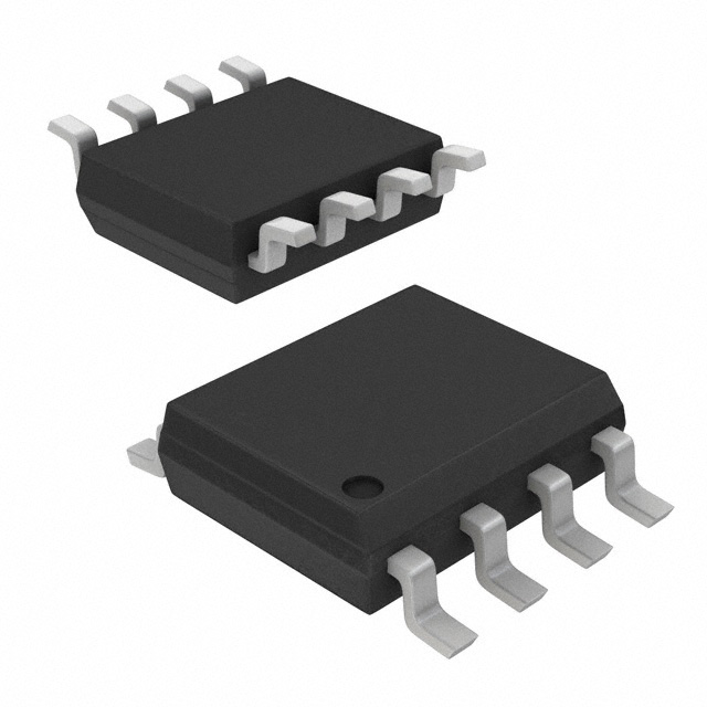
Diodes Incorporated AP3776BMTR-G1
- Part No.:
- AP3776BMTR-G1
- Manufacturer:
- Diodes Incorporated
- Category:
- AC DC Converters, Offline Switches
- Package:
- 8-SOIC (0.154", 3.90mm Width)
- Datasheet:
-
 AP3776BMTR-G1.pdf
- Description:
- IC OFFLINE SWITCH FLYBACK 8SO
- Quantity:
- Payment:

- Shipping:

Inventory:4,862
Please send an inquiry. Send us your inquiry, and we will respond immediately.
Product details
Overview
AP3776BMTR-G1 from Diodes Incorporated is a primary-side regulation (PSR) AC/DC controller IC for offline flyback converters in battery chargers and adapters. It delivers constant voltage (CV) and constant current (CC) regulation without optocoupler or secondary-side feedback, achieves ≤10 mW no-load input power, <1 s startup time, and operates in discontinuous conduction mode (DCM) with PFM control. Used in 5 V/1–2.4 A shaver and portable device chargers.
For engineers reviewing the AP3776BMTR-G1 datasheet, AP3776BMTR-G1 pinout, AP3776BMTR-G1 application, or AP3776BMTR-G1 equivalent, this page details its PSR architecture, cable compensation, semi-valley turn-on, random frequency modulation for EMI reduction, and compatibility with AP4341/APR343/APR3415 for under-shoot suppression and efficiency optimization.
Technical Context
The AP3776BMTR-G1 implements primary-side regulation via auxiliary winding voltage sampling at the FB pin, using a multi-segment peak current threshold (VCS_H/VCS_M/VCS_L) to maintain switching frequency >24 kHz across load range and eliminate audible noise. Its CV loop regulates output by adjusting D1 off-time based on sampled VAUX at 2/3 of secondary conduction period.
In CC mode, it fixes the Tons/Toffs ratio at 1:4 while maintaining constant primary peak current, enabling precise current regulation independent of output cable drop. Line compensation-via FB-derived current injected into CS through RLINE-corrects primary current error caused by input voltage variation, ensuring ±3% line regulation of output current.
Key Specifications
| Parameter | Value and Actual Design Meaning |
|---|---|
| Topology | Flyback converter in DCM with PFM control - enables high efficiency at light loads and eliminates need for loop compensation. |
| No-load Input Power | ≤10 mW - meets "Super Star" energy efficiency standard for standby operation in EU and global regulations. |
| Startup Threshold | 11–14 V - ensures reliable turn-on after bulk capacitor charges; minimal operating voltage is 5.3–7.0 V post-startup. |
| FB Voltage Threshold | 3.64–3.76 V - sets nominal output voltage reference; OVP triggers at 6.5–8.5 V for safety shutdown. |
| VCS Threshold | 425–465 mV - defines primary peak current limit; used for both CV and CC regulation with temperature-compensated accuracy. |
| Cable Compensation | 2–4% ΔVFB/VFB - injects rising voltage proportional to CPC pin voltage to offset fixed output cable voltage drop. |
| Max Switching Frequency | ≈84 kHz - upper bound for normal operation; multi-segment VCS maintains >24 kHz down to ultra-light load to avoid audio-band noise. |
| Protection Features | OVP (FB >7.5 V), SCP (FB <2.5 V), OTP (130 °C trip), hiccup-mode restart - ensures robust field reliability without external supervision. |
Pinout & Package
AP3776BMTR-G1 is housed in an SO-8 package (surface-mount, 150 °C max junction temperature, θJA = 190 °C/W), with exposed pad not electrically connected. Pin functions are validated per Diodes DS36737 Rev. 7–3.
| Pin/Terminal | Circuit Role | Design Meaning |
|---|---|---|
| 1 IS | Primary current sense input | Connects to current-sense resistor (RCS) to monitor primary-side current slope and detect peak for PWM termination. |
| 2 EM | External MOSFET source connection | Direct tie to source of external power MOSFET; enables internal sensing path for leading-edge blanking and gate drive timing. |
| 3 VCC | IC power supply | Supplied by auxiliary winding; UVLO starts at 11–14 V, sustains operation down to 5.3–7.0 V. |
| 4 OUT | Gate driver output | Drives external MOSFET base/gate with 500 mA sink / 67 mA source capability; includes 14–16 V clamp. |
| 5 GND | Analog/digital ground reference | Common return for all internal circuits; must be low-impedance and separated from power ground in layout. |
| 6 VCS | Current sense voltage input | Receives filtered voltage from IS pin; compared against multi-segment VCS reference for peak current control. |
| 7 CPC | Cable compensation capacitor terminal | Connects external capacitor to generate voltage proportional to load, enabling fixed % output voltage boost. |
| 8 FB | Voltage feedback input | Samples auxiliary winding voltage during secondary conduction; sets CV setpoint and triggers OVP/SCP protection. |
Key Features
| Feature | Design Value |
|---|---|
| Optocoupler-free PSR | Eliminates secondary-side feedback components, reducing BOM cost and PCB area while improving long-term reliability. |
| Semi-valley turn-on | Reduces switching loss by triggering MOSFET when drain voltage reaches local valley, increasing average efficiency by ~1.5%. |
| Random frequency modulation | Spreads EMI spectrum across 24–84 kHz band, lowering peak radiated emissions by up to 10 dB compared to fixed-frequency PFM. |
| Built-in soft start | Prevents inrush current and output overshoot during power-up by gradually increasing switching frequency and duty cycle. |
| Audio noise suppression | Multi-segment VCS control prevents switching frequency from falling into 20 Hz–20 kHz audible range under all load conditions. |
| Line compensation | Compensates primary current error due to input voltage variation, achieving ±3% output current regulation across 90–264 VAC input. |
Applications
| USB-C Portable Charger | Low-Power Shaver Adapter |
|---|---|
Use Scenario: Compact 5 V/2 A wall adapter for personal grooming devices requiring CE/UKCA certification and <30 mW no-load power. IC Role / Device Role / Timing Role: Primary-side controller managing DCM flyback operation, real-time CV/CC regulation, and cable drop compensation via CPC pin. Use Value: Enables single-layer PCB design with no optocoupler or TL431, reducing component count by 4 and meeting IEC 62368-1 creepage requirements. |
Use Scenario: 5 V/1 A charger for cordless shavers with strict acoustic noise limits and <10 mW standby consumption. IC Role / Device Role / Timing Role: PSR controller implementing semi-valley switching and random frequency modulation to suppress audible transformer whine. Use Value: Guarantees >24 kHz minimum switching frequency across full load range, eliminating perceptible noise even at 0.1% load. |
| Smartphone Auxiliary Supply | IoT Sensor Hub Power |
Use Scenario: Secondary 5 V/1 A isolated supply in multi-rail IoT gateway, powering USB peripherals and BLE modules. IC Role / Device Role / Timing Role: Standby-optimized controller providing fast transient response (<100 µs delay) and tight CV regulation (±2%) over line/load. Use Value: Delivers <1 s startup and <10 mW no-load power, extending system battery life during deep sleep modes. |
Use Scenario: Low-power 5 V/500 mA auxiliary supply for industrial sensor nodes requiring AEC-Q200-aligned reliability. IC Role / Device Role / Timing Role: Fault-tolerant PSR IC with integrated OVP, SCP, OTP, and RCS short protection-no external supervision needed. Use Value: Supports unattended 10-year field deployment with hiccup-mode recovery from sustained short-circuit events. |
Equivalent & Alternatives
The following parts are listed as comparable options for similar primary-side regulation controller applications.
| Alternative Part | Technical Difference | Application Difference | Selection Advice |
|---|---|---|---|
| AP3190T | Successor IC with improved 5 mW no-load power, enhanced line regulation (±1.5%), and integrated 650 V MOSFET. | Designed for new designs targeting latest Energy Star v3.0 and CoC Tier 2 standards; replaces AP3776B in green-field projects. | Select AP3190T for new designs requiring lower standby power, higher integration, and extended lifecycle support. |
| AP43770 | Higher-current PSR controller (supports up to 5 A), adds QR mode, and features programmable cable compensation via external resistor. | Targeted at 5 V/3–5 A fast-charging adapters with USB PD 3.0 compliance; lacks LL mode but offers faster dynamic response. | Choose AP43770 when scaling output current beyond 2.4 A or requiring QR topology for >90% peak efficiency. |
Compared with AP3776BMTR-G1, AP3190T reduces no-load power by 50% and integrates power switch, while AP43770 supports higher current and QR operation but requires more complex layout and lacks ultra-low-light-load optimization.
Availability
AP3776BMTR-G1 is available at Aetrix Electronics and suitable for USB-C portable chargers, low-power shaver adapters, smartphone auxiliary supplies, and IoT sensor hub power systems requiring stable component supply and legacy design continuity.
Supply support for AP3776BMTR-G1 includes scheduled delivery planning, volume procurement assistance, BOM continuity management, traceable sourcing, and lifecycle availability coordination for OEM customers, industrial embedded developers, connected-device designers, and electronics production programs.
Manufacturer
Diodes Incorporated is a global semiconductor company specializing in discrete, analog, and mixed-signal ICs, with manufacturing certified to IATF 16949 and environmental compliance to RoHS 3 and halogen-free standards.
The AP3776B belongs to Diodes' AC/DC PSR controller product line, engineered specifically for cost-sensitive, space-constrained offline chargers and adapters demanding ultra-low standby power and optocoupler-free operation.
FAQ
What is the purpose of the CPC pin on AP3776BMTR-G1?
The CPC (Cable Compensation) pin accepts an external capacitor to generate a voltage proportional to load current. This voltage is added to the internal FB reference, producing a fixed percentage increase in regulated output voltage-typically 2–4%-to offset resistive drop across output cables, ensuring accurate voltage delivery at the device connector.
How does AP3776BMTR-G1 achieve <10 mW no-load power?
It combines multiple techniques: ultra-low quiescent current (100 µA in LL mode), automatic transition to Low Light (LL) mode at no load, gated auxiliary winding supply, and optimized internal bias circuitry. In LL mode, ICC(STB) drops to 100 µA, and switching frequency is reduced while maintaining VCC above operational threshold via APR343-triggered pulse bursts.
Can AP3776BMTR-G1 operate without AP4341 or APR343?
Yes-it functions as a standalone PSR controller for CV/CC regulation in standard flyback topologies. However, AP4341/APR343/APR3415 are optional companion ICs that enhance performance: APR343 enables ultra-low standby power via LL mode awakening, while AP4341 improves under-shoot response and dynamic load regulation.
What protection mechanisms are built into AP3776BMTR-G1?
It integrates overvoltage protection (OVP) on FB pin (6.5–8.5 V), short-circuit protection (SCP) triggered by FB <2.5 V, overtemperature protection (OTP) at 130 °C with 20 °C hysteresis, RCS short detection, and open-circuit feedback (OCKP) monitoring. All protections initiate hiccup-mode restart or controlled shutdown without external components.
AP3776BMTR-G1 Specifications
- Product attributes
- Attribute value
- Manufacturer:
- Diodes Incorporated
- Series:
- -
- Package/Case:
- 8-SOIC (0.154", 3.90mm Width)
- Packaging:
- Tape & Reel (TR)
- Product Status:
- Active
- Output Isolation:
- Isolated
- Internal Switch(s):
- No
- Voltage - Breakdown:
- -
- Topology:
- Flyback
- Voltage - Start Up:
- 13 V
- Voltage - Supply (Vcc/Vdd):
- 6.1V ~ 28V
- Duty Cycle:
- -
- Frequency - Switching:
- -
- Power (Watts):
- -
- Fault Protection:
- Over Temperature, Over Voltage, Short Circuit
- Control Features:
- -
- Operating Temperature:
- -40°C ~ 85°C (TA)
- Grade:
- -
- Qualification:
- -
- Supplier Device Package:
- 8-SO
- Mounting Type:
- Surface Mount
AP3776BMTR-G1 FAQ
1.How can I place an order for AP3776BMTR-G1 through Aetrix?
Please submit a Request for Quotation (RFQ) for AP3776BMTR-G1 on Aetrix. Our sales agent will provide a competitive quotation and guide you through the order confirmation once you accept the terms.
2.Are the price and stock information for AP3776BMTR-G1 reliable?
The price and inventory of AP3776BMTR-G1 are updated periodically and may fluctuate due to market conditions. Stock and pricing data are typically refreshed every 24 hours. Quotation validity for AP3776BMTR-G1 is usually 5 days.
3.What payment methods are accepted for AP3776BMTR-G1?
We accept Wire Transfer, PayPal, Credit Card, Western Union, MoneyGram, and Escrow for AP3776BMTR-G1 transactions.
Note: Certain payment methods may incur a processing fee.
4.How is shipping managed for AP3776BMTR-G1?
AP3776BMTR-G1 orders can be shipped via leading logistics carriers, including DHL, UPS, FedEx, TNT, or Registered Mail.
Once your AP3776BMTR-G1 order is processed, you will receive an email with the shipment details and tracking number.
Note: Tracking information may take up to 24 hours to appear. Express delivery typically takes 3–5 business days.
5.How can I obtain technical support or documentation for AP3776BMTR-G1?
For technical support, including AP3776BMTR-G1 datasheets, pinout diagrams, or application guidance, please contact our engineering support team. They can provide detailed documentation and assistance for your AP3776BMTR-G1 requirements.
6.How does Aetrix verify that AP3776BMTR-G1 is sourced from the original manufacturer or authorized distributors?
All AP3776BMTR-G1 products on Aetrix are procured from qualified distributors and authorized channels. Our dedicated quality assurance team conducts strict verification, including traceability checks and, if necessary, third-party testing. This ensures that AP3776BMTR-G1 meets industry standards.
7.What is the process for return or replacement of AP3776BMTR-G1?
All AP3776BMTR-G1 units undergo pre-shipment inspection (PSI). If there is an issue with AP3776BMTR-G1, returns or replacements are accepted under the following conditions:
1.Quantity discrepancies, incorrect items, or visible external defects (such as breakage or corrosion), acknowledged by Aetrix.
2.The issue is reported within 90 days of delivery.
3.The AP3776BMTR-G1 part is unused and in its original packaging.
Return procedure for AP3776BMTR-G1:
1.Submit a request within 90 days.
2.Obtain a Return Material Authorization (RMA) from Aetrix.
AP3776BMTR-G1 Tags
-
LNK6407D-TL
Power Integrations
-
LNK3204D-TL
Power Integrations

-
SR10LG-G
Microchip Technology
-
TNY285DG-TL
Power Integrations
-
LNK304DN-TL
Power Integrations
-
TNY285KG-TL
Power Integrations
-
LNK3206D-TL
Power Integrations
-
LNK623DG-TL
Power Integrations
-
TNY286PG
Power Integrations
-
LNK624DG-TL
Power Integrations
-
LNK604DG-TL
Power Integrations

-
UCC28704DBVR-1
Texas Instruments
Tech Hub

Operational amplifier guide covering op amp basics, feedback, ideal vs real op amps, common configurations, buffer circuits, offset, bias current, gain-bandwidth, slew rate, rail-to-rail limits and sel…

Jumper cables guide covering safe connection order, red and black clamp placement, final ground connection, cable gauge, length, clamp quality, copper vs CCA cables, jump starter comparison and battery…

LDO regulator guide covering low dropout voltage, power dissipation, thermal design, PSRR, output noise, capacitor stability, adjustable LDO circuits, LDO vs buck converter and datasheet selection chec…

Conditional Access Module guide covering CAM meaning, CI/CI+ interface, smart card authorization, DVB security workflow, TV and set-top box compatibility, internal electronics, ESD protection, connecto…

Guide to electronic component obsolescence covering EOL risk, PCN/PDN notices, last-time buy planning, replacement options, form-fit-function validation, counterfeit risk and BOM lifecycle management.

18650 battery guide covering lithium-ion cell basics, 3.6V/3.7V voltage, 4.2V charging, mAh and Wh capacity, protected cells, chargers, BMS, series-parallel packs, holders, welding and sourcing checks.…

Hall effect sensor guide covering working principle, linear and digital sensors, Arduino circuits, current sensing, speed detection, automotive applications, A3144 examples, signal filtering and datash…

Product Change Notification guide for electronic components, covering PCN meaning, PCN vs PDN/EOL, common change types, risk levels, form-fit-function review, engineering validation, BOM control, LTB/L…

A practical guide to blend door actuators, covering HVAC function, symptoms, location, AC and heater issues, reset and calibration, replacement cost, electrical diagnosis, compatibility checks, and rep…

Engineering guide to Raspberry Pi alternatives, covering chip-level differences, Orange Pi, ROCK, Jetson, Banana Pi, NanoPi, Compute Module, Pico, GPIO, camera, HAT compatibility, and replacement risks…


