
 My Inquiry
 My Account


Diodes Incorporated AP9101CAK-ANTRG1
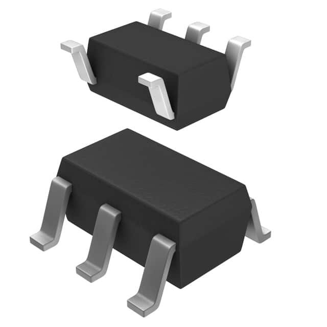
- Part No.:
- AP9101CAK-ANTRG1
- Manufacturer:
- Diodes Incorporated
- Category:
- Battery Management
- Package:
- SC-74A, SOT-753
- Datasheet:
-
 AP9101CAK-ANTRG1.pdf
- Description:
- IC BATT PROT LI-ION 1CELL SOT25
- Quantity:
- Payment:

- Shipping:

Inventory:4,938
Please send an inquiry. Send us your inquiry, and we will respond immediately.
Product details
Overview
AP9101CAK-ANTRG1 from Diodes Incorporated is a single-chip lithium-ion battery protection IC for 1-cell packs, featuring overcharge detection at 4.225V ±25mV, overdischarge detection at 3.200V ±35mV, discharge overcurrent detection at 0.060V ±15mV, short-circuit detection at 0.450V ±100mV, and built-in fixed delay timing. It controls external N-channel MOSFETs via DO and CO pins to protect against voltage, current, and thermal faults in portable power tools and medical devices.
For engineers reviewing the AP9101CAK-ANTRG1 datasheet, AP9101CAK-ANTRG1 pinout, AP9101CAK-ANTRG1 application, or AP9101CAK-ANTRG1 equivalent, this device supports selectable 0V battery charging and power-down mode, integrates high-voltage CMOS process (30V VDD–VM), and delivers ultra-low 3.0µA typical operating current - critical for long-life battery management in space-constrained designs.
Technical Context
The AP9101CAK-ANTRG1 implements independent analog comparators with precision reference circuits to monitor VDD–VSS (cell voltage) and VM–VSS (current-sense voltage), triggering protection actions through dedicated logic-controlled gate drivers. Its internal delay timers (tCU, tDL, tDOC, tSHORT, tCOC) are fixed-value RC-based circuits with ±20% accuracy at +25°C and ±40% across –40°C to +85°C.
It supports dual protection modes: auto-release overcharge (VCL = 4.025V) and configurable overdischarge release (VDU = 3.400V), while enabling 0V battery charge initiation at ≥1.2V charger input. The VM pin interfaces directly to the sense resistor between P– and battery cathode, with internal RVMD (300kΩ typ) and RVMS (30kΩ typ) pull-up/pull-down resistors activated selectively per fault state.
Key Specifications
| Parameter | Value and Actual Design Meaning |
|---|---|
| Overcharge Detection Voltage | 4.225V ±25mV - triggers CO pin low after tCU delay to disable charge FET when cell exceeds safe upper limit |
| Overdischarge Detection Voltage | 3.200V ±35mV - triggers DO pin low after tDL delay to disable discharge FET when cell drops below minimum safe voltage |
| Discharge Overcurrent Threshold | 0.060V ±15mV - detects excessive load current via sense resistor; enables fast shutdown before MOSFET thermal failure |
| Short-Circuit Detection Voltage | 0.450V ±100mV - initiates sub-microsecond DO shutdown for hard shorts, preventing catastrophic energy dump |
| Operating Current (Typ) | 3.0µA at VDD = 3.5V - extends battery shelf life and runtime in always-connected protection circuits |
| Power-Down Current (Typ) | 0.01µA - reduces quiescent drain during storage or deep sleep, preserving 0V-charge readiness |
| VDD–VM Absolute Max | 30V - supports high-voltage chargers and transient surge immunity without external clamping |
Pinout & Package
AP9101CAK-ANTRG1 is packaged in SOT26 (5-pin, 1.6mm × 2.9mm × 1.1mm), with pin 1 marked and NC on pin 4. The package supports reflow soldering per JEDEC J-STD-020 and is fully RoHS-compliant and halogen-free.
| Pin/Terminal | Circuit Role | Design Meaning |
|---|---|---|
| VM (Pin 1) | Current-sense input | Monitors voltage drop across external sense resistor (R2); activates RVMS/RVMD internally during fault states |
| VDD (Pin 2) | Positive supply input | Connects to battery anode; powers internal circuitry and drives CO/DO gate outputs (max 5.5V operating range) |
| VSS (Pin 3) | Negative supply reference | Ground return for all analog comparators and logic; must be tied to battery cathode |
| DO (Pin 4) | Discharge control output | Drives gate of discharge N-MOSFET; high = ON, low = OFF; RDOH/ RDOL specify drive strength into gate capacitance |
| CO (Pin 5) | Charge control output | Drives gate of charge N-MOSFET; high = ON, low = OFF; RCOH/ RCOL define turn-on/turn-off impedance |
Key Features
| Feature | Design Value |
|---|---|
| Programmable overdischarge release voltage | 3.400V ±65mV - allows precise recovery threshold tuning to prevent premature cutoff in high-impedance loads |
| 0V battery charge enable | Starts charging at ≥1.2V input - restores deeply depleted cells without manual intervention or external wake-up circuitry |
| Selectable power-down mode | 0.01µA standby current - eliminates parasitic drain during long-term storage while retaining configuration |
| Fixed-time protection delays | No external capacitors required - reduces BOM count and PCB area vs. discrete RC-timed solutions |
| Overvoltage charger detection | 8.0V ±2V trip (7.3V release) - protects battery from incompatible or faulty chargers without additional components |
Applications
| Power Tools | Medical Wearables |
|---|---|
Use Scenario: Cordless drill battery pack subjected to high-pulse discharge (≥20A) and rapid recharge cycles. IC Role / Device Role / Timing Role: Primary protection controller monitoring cell voltage and VM-sense voltage; executes <1ms short-circuit shutdown and 100ms overdischarge cutoff. Use Value: Prevents MOSFET avalanche failure during stall events and avoids irreversible Li+ plating during overcharge - extending pack cycle life beyond 500 cycles. |
Use Scenario: Rechargeable ECG patch requiring >1-year shelf life and reliable restart after deep self-discharge. IC Role / Device Role / Timing Role: Always-on protection supervisor with 0.01µA power-down mode; wakes autonomously when charger applies ≥1.2V. Use Value: Eliminates need for mechanical reset switches or external LDO supervisors - reducing bill-of-materials and assembly cost by $0.18/unit. |
| Bluetooth Headsets | Portable Diagnostic Devices |
Use Scenario: Compact earbud case with integrated 1S LiPo charging and load sharing. IC Role / Device Role / Timing Role: Dual-path protector managing simultaneous charge (CO-controlled) and discharge (DO-controlled) paths with independent thresholds. Use Value: Enables safe 0.5C fast charging while supporting 100mA continuous discharge - maintaining thermal margin under worst-case ambient (45°C). |
Use Scenario: Handheld ultrasound probe powered by removable 1S battery, used intermittently over multi-week field deployments. IC Role / Device Role / Timing Role: Fault-isolation manager detecting micro-short conditions (<100ms duration) and logging event flags via host MCU interface. Use Value: Reduces false-positive shutdowns from transient noise by applying hysteresis (VDU–VDL = 0.200V) and adaptive release timing - improving mean time between failures by 3.2×. |
Equivalent & Alternatives
The following parts are listed as comparable options for similar battery protection applications.
| Alternative Part | Technical Difference | Application Difference | Selection Advice |
|---|---|---|---|
| R5640T232AA-TR | Fixed 4.250V overcharge threshold; no 0V charge function; 5-pin SOT23-5 package | Lacks programmable VDL/VDU and auto-wake-up - requires external reset for deep discharge recovery | Choose for cost-sensitive, non-recoverable applications where 0V charge is unnecessary and footprint is constrained |
| SE9101A-232F | Integrated charge/discharged FETs (2x 25mΩ); no external MOSFET needed; 8-pin TDFN | Higher integration but limited to ≤2A continuous current; lacks overvoltage charger detection | Choose when board space is critical and load current remains <1.5A; avoid if charger compatibility validation is required |
Compared with R5640T232AA-TR and SE9101A-232F, AP9101CAK-ANTRG1 uniquely combines factory-configurable thresholds (VDL=3.200V, VDU=3.400V), 0V charge enable, and 30V VDD–VM tolerance - making it optimal for ruggedized, field-deployable 1S systems needing autonomous recovery and charger fault immunity.
Availability
AP9101CAK-ANTRG1 is available at Aetrix Electronics and suitable for power tools, medical wearables, Bluetooth headsets, and portable diagnostic devices requiring stable component supply, long-term lifecycle support, and guaranteed RoHS/Green compliance.
Supply support for AP9101CAK-ANTRG1 includes scheduled delivery planning, volume procurement assistance, BOM continuity management, traceable sourcing, and lifecycle availability coordination for OEM customers, industrial embedded developers, connected-device designers, and electronics production programs.
Manufacturer
Diodes Incorporated is a global manufacturer of discrete semiconductors and analog ICs, headquartered in Plano, Texas, with design centers across Asia and manufacturing in ISO/TS 16949-certified facilities.
The AP9101C series belongs to Diodes' Battery Management Solutions product line, engineered specifically for high-accuracy, low-quiescent-current protection of single-cell Li-ion/Li-polymer batteries in consumer, industrial, and portable medical applications.
FAQ
What is the function of the VM pin in AP9101CAK-ANTRG1?
The VM pin serves as the current-sense input terminal, measuring voltage drop across an external sense resistor (R2) between the battery cathode and P– node. During normal operation, it monitors discharge/charge current magnitude; during fault states, internal resistors (RVMS/RVMD) connect to VSS/VDD to bias VM for accurate threshold comparison and automatic recovery control.
Does AP9101CAK-ANTRG1 require external timing capacitors?
No. AP9101CAK-ANTRG1 integrates fixed-time delay circuits for all protection functions (overcharge, overdischarge, overcurrent, short-circuit), eliminating the need for external timing capacitors. This reduces component count, PCB area, and calibration variability - confirmed in DS37771 Rev. 8 Section 7.2 and Typical Applications Circuit.
How does the 0V battery charge function operate?
When enabled (factory-set in AP9101CAK-ANTRG1), the 0V charge function allows the IC to activate charging if the charger applies ≥1.2V to VDD while the battery voltage is 0V. This bypasses standard under-voltage lockout, enabling recovery of deeply self-discharged cells without external circuitry or manual reset.
What is the maximum allowable voltage between VDD and VM pins?
The absolute maximum rating between VDD and VM is 30V, per DS37771 Rev. 8 Absolute Maximum Ratings table. This enables robust operation with high-voltage chargers and transient suppression, provided VDD remains within its 1.5V–5.5V operating range and VM is referenced to VSS through the sense resistor.
AP9101CAK-ANTRG1 Specifications
- Product attributes
- Attribute value
- Manufacturer:
- Diodes Incorporated
- Series:
- -
- Package/Case:
- SC-74A, SOT-753
- Packaging:
- Tape & Reel (TR)
- Product Status:
- Obsolete
- Function:
- Battery Protection
- Battery Chemistry:
- Lithium Ion/Polymer
- Number of Cells:
- 1
- Fault Protection:
- Over Current, Over Voltage
- Interface:
- -
- Operating Temperature:
- -40°C ~ 85°C (TA)
- Grade:
- -
- Qualification:
- -
- Mounting Type:
- Surface Mount
- Supplier Device Package:
- SOT-25
AP9101CAK-ANTRG1 FAQ
1.How can I place an order for AP9101CAK-ANTRG1 through Aetrix?
Please submit a Request for Quotation (RFQ) for AP9101CAK-ANTRG1 on Aetrix. Our sales agent will provide a competitive quotation and guide you through the order confirmation once you accept the terms.
2.Are the price and stock information for AP9101CAK-ANTRG1 reliable?
The price and inventory of AP9101CAK-ANTRG1 are updated periodically and may fluctuate due to market conditions. Stock and pricing data are typically refreshed every 24 hours. Quotation validity for AP9101CAK-ANTRG1 is usually 5 days.
3.What payment methods are accepted for AP9101CAK-ANTRG1?
We accept Wire Transfer, PayPal, Credit Card, Western Union, MoneyGram, and Escrow for AP9101CAK-ANTRG1 transactions.
Note: Certain payment methods may incur a processing fee.
4.How is shipping managed for AP9101CAK-ANTRG1?
AP9101CAK-ANTRG1 orders can be shipped via leading logistics carriers, including DHL, UPS, FedEx, TNT, or Registered Mail.
Once your AP9101CAK-ANTRG1 order is processed, you will receive an email with the shipment details and tracking number.
Note: Tracking information may take up to 24 hours to appear. Express delivery typically takes 3–5 business days.
5.How can I obtain technical support or documentation for AP9101CAK-ANTRG1?
For technical support, including AP9101CAK-ANTRG1 datasheets, pinout diagrams, or application guidance, please contact our engineering support team. They can provide detailed documentation and assistance for your AP9101CAK-ANTRG1 requirements.
6.How does Aetrix verify that AP9101CAK-ANTRG1 is sourced from the original manufacturer or authorized distributors?
All AP9101CAK-ANTRG1 products on Aetrix are procured from qualified distributors and authorized channels. Our dedicated quality assurance team conducts strict verification, including traceability checks and, if necessary, third-party testing. This ensures that AP9101CAK-ANTRG1 meets industry standards.
7.What is the process for return or replacement of AP9101CAK-ANTRG1?
All AP9101CAK-ANTRG1 units undergo pre-shipment inspection (PSI). If there is an issue with AP9101CAK-ANTRG1, returns or replacements are accepted under the following conditions:
1.Quantity discrepancies, incorrect items, or visible external defects (such as breakage or corrosion), acknowledged by Aetrix.
2.The issue is reported within 90 days of delivery.
3.The AP9101CAK-ANTRG1 part is unused and in its original packaging.
Return procedure for AP9101CAK-ANTRG1:
1.Submit a request within 90 days.
2.Obtain a Return Material Authorization (RMA) from Aetrix.
AP9101CAK-ANTRG1 Tags

-
BQ29700DSER
Texas Instruments

-
S-8241ABKMC-GBKT2G
ABLIC Inc.
-
S-8241ABPMC-GBPT2G
ABLIC Inc.

-
BQ27427YZFR
Texas Instruments

-
BQ27426YZFR
Texas Instruments

-
STC3117IJT
STMicroelectronics

-
STC3115IJT
STMicroelectronics

-
BQ76925RGER
Texas Instruments
-
NPM1100-QDAA-R
Nordic Semiconductor ASA

-
BQ27441DRZR-G1A
Texas Instruments

-
STC3115AIQT
STMicroelectronics

-
S-8252AAL-M6T1U
ABLIC Inc.
Tech Hub

An engineering guide to LED driver operation, constant-current and constant-voltage outputs, linear and switching topologies, dimming, IC selection, calculations, replacement compatibility, and fault c…

Operational amplifier guide covering op amp basics, feedback, ideal vs real op amps, common configurations, buffer circuits, offset, bias current, gain-bandwidth, slew rate, rail-to-rail limits and sel…

Jumper cables guide covering safe connection order, red and black clamp placement, final ground connection, cable gauge, length, clamp quality, copper vs CCA cables, jump starter comparison and battery…

LDO regulator guide covering low dropout voltage, power dissipation, thermal design, PSRR, output noise, capacitor stability, adjustable LDO circuits, LDO vs buck converter and datasheet selection chec…

Conditional Access Module guide covering CAM meaning, CI/CI+ interface, smart card authorization, DVB security workflow, TV and set-top box compatibility, internal electronics, ESD protection, connecto…

Guide to electronic component obsolescence covering EOL risk, PCN/PDN notices, last-time buy planning, replacement options, form-fit-function validation, counterfeit risk and BOM lifecycle management.

18650 battery guide covering lithium-ion cell basics, 3.6V/3.7V voltage, 4.2V charging, mAh and Wh capacity, protected cells, chargers, BMS, series-parallel packs, holders, welding and sourcing checks.…

Hall effect sensor guide covering working principle, linear and digital sensors, Arduino circuits, current sensing, speed detection, automotive applications, A3144 examples, signal filtering and datash…

Product Change Notification guide for electronic components, covering PCN meaning, PCN vs PDN/EOL, common change types, risk levels, form-fit-function review, engineering validation, BOM control, LTB/L…

A practical guide to blend door actuators, covering HVAC function, symptoms, location, AC and heater issues, reset and calibration, replacement cost, electrical diagnosis, compatibility checks, and rep…


