
 My Inquiry
 My Account


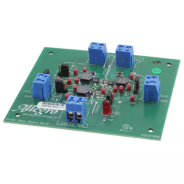
Allegro MicroSystems APEK4491EES-01-T-DK
- Part No.:
- APEK4491EES-01-T-DK
- Manufacturer:
- Allegro MicroSystems
- Package:
- Datasheet:
-
 APEK4491EES-01-T-DK.pdf
- Description:
- EVAL BOARD FOR A4491
- Quantity:
- Payment:

- Shipping:

Inventory:4,000
Please send an inquiry. Send us your inquiry, and we will respond immediately.
Product details
Overview
APEK4491EES-01-T-DK from Allegro MicroSystems is a triple-output, fixed-frequency synchronous buck switching regulator IC with independent enable control, 4.5–23 V input range, 550 kHz switching frequency, and 4 × 4 mm QFN-20 package. It delivers up to 1.5 A per channel (4.5 A total) for power management in multi-rail embedded systems such as inkjet printers and industrial controllers.
For engineers reviewing the APEK4491EES-01-T-DK datasheet, APEK4491EES-01-T-DK pinout, APEK4491EES-01-T-DK application, or APEK4491EES-01-T-DK equivalent, key selection criteria include interleaved multiphase operation for EMI reduction, user-adjustable POR delay via CPOR pin, internal compensation, and independent ENBx sequencing capability across three regulated outputs.
Technical Context
The APEK4491EES-01-T-DK integrates three peak-current-mode controlled buck converters sharing a single 550 kHz clock with 120° phase shift to minimize input ripple and EMI. Each channel features independent soft-start (1.25 ms typical), pulse-skipping at light load, and programmable PORZ assertion based on FBx voltage thresholds and CPOR capacitor value.
It employs an internal charge pump (VCP) to sustain gate drive across the full 4.5–23 V input range and includes comprehensive protection: overcurrent (2.0 A min peak), VBB undervoltage warning (3.6 V), shutdown (3.5 V with external VDD), and thermal shutdown (165°C with 15°C hysteresis).
Key Specifications
| Parameter | Value and Actual Design Meaning |
|---|---|
| Input Voltage Range | 4.5 V to 23 V - supports wide-input industrial and printer power rails without external pre-regulation |
| Switching Frequency | 550 kHz ±80 kHz - enables use of small ceramic output capacitors and low-cost inductors |
| Output Current (per channel) | 1.5 A - sufficient for powering microcontroller cores, I/O rails, and logic in compact systems |
| Feedback Reference Voltage | 0.8 V ±1% - sets precise output voltage via external resistor divider; enables 1.0 V, 3.3 V, and 5.0 V configurations |
| Power-On Reset Delay | 75–155 ms (with 470 nF CPOR) - configurable system-ready timing signal for sequenced firmware boot |
| Thermal Resistance (RθJA) | 37 °C/W - achievable on standard 4-layer JEDEC PCB; requires exposed pad soldered to ground plane |
| Operating Temperature | –40 °C to +85 °C - qualified for industrial ambient environments without derating |
Pinout & Package
Package: 20-contact, 4 mm × 4 mm, 0.75 mm nominal height QFN with exposed thermal pad (ES suffix). Requires thermal vias under pad connected to GND plane.
| Pin/Terminal | Circuit Role | Design Meaning |
|---|---|---|
| FB1, FB2, FB3 | Feedback inputs for REG1/REG2/REG3 | Monitor output voltage via resistor divider; reference is 0.8 V; bias current ≤ ±100 nA minimizes divider error |
| ENB1, ENB2, ENB3 | Independent enable inputs (active high) | Allow per-channel power sequencing; VIH ≥ 2.0 V, VIL ≤ 0.8 V; hysteresis 300–500 mV prevents chatter |
| LX1, LX2, LX3 | Switch node outputs | Drive external inductor/diode; rated –0.7 V to 23 V; must be routed with low-inductance layout to reduce EMI |
| VBB1, VBB2, VBB3 | Input supply pins for each regulator | Internally tied together externally; support shared or isolated input sources; max 24 V absolute rating |
| PORZ | Open-drain power-on-reset flag | Active-low signal indicating all enabled regulators are within 85% of target; sinks 1 mA at 0.4 V max |
| CPOR | POR delay adjustment terminal | Connects to external capacitor (e.g., 470 nF) to set tPOR = 2.131×10⁵ × CPOR; layout critical to avoid leakage |
| VCP, CP1, CP2 | Charge pump reservoir and terminals | Generate boosted gate drive for internal MOSFETs across full input range; requires 100 nF ceramic capacitor (C1) |
| VDD | Bias supply input | Accepts 3.3–5.5 V external supply to reduce dissipation and lower VBB UVLO threshold |
| GND, PGND | Analog and power ground returns | GND1 and PGND1 must be connected externally; thermal pad (PAD) must connect to GND plane via ≥4 thermal vias |
Key Features
| Feature | Design Value |
|---|---|
| Triple buck architecture in single QFN-20 | Reduces board area by >40% vs. discrete solutions; eliminates inter-channel timing mismatch and layout complexity |
| Interleaved 120° phase-shifted switching | Cuts input capacitor RMS current by ~50% and lowers peak EMI amplitude versus synchronized operation |
| Independent ENBx control with soft-start | Enables staggered power-up of subsystems (e.g., core → I/O → interface) without external timers or logic |
| User-configurable PORZ with CPOR pin | Allows precise synchronization of system reset with stable rail delivery-no external RC network required |
| Internal compensation network | Eliminates need for external compensation components; simplifies design validation and reduces BOM count |
| Comprehensive fault protection | Detects VBB undervoltage (warning + shutdown), overtemperature (165°C), and per-channel overload-auto-restarts after fault clears |
Applications
| Photo & Inkjet Printers | Industrial Control Panels |
|---|---|
|
Use Scenario: Powering ASIC, motor drivers, and sensor interfaces in compact desktop printers with tight thermal constraints. IC Role / Device Role / Timing Role: Triple-output PMIC delivering 1.0 V (logic core), 3.3 V (I/O), and 5.0 V (motor driver logic) from a single 12 V input rail. Use Value: Interleaved switching reduces input ripple and allows smaller bulk capacitors; independent ENBx enables safe motor startup after logic initialization. |
Use Scenario: Providing clean, sequenced rails for PLC I/O modules operating in factory-floor environments with wide ambient temperature swings. IC Role / Device Role / Timing Role: Centralized power controller managing 3.3 V FPGA configuration, 5 V analog front-end, and 1.8 V ADC reference from 24 V DC bus. Use Value: PORZ flag ensures firmware only boots after all rails reach regulation; thermal shutdown protects against enclosure overheating during extended operation. |
| Point-of-Sale Terminals | Security System Controllers |
|
Use Scenario: Compact embedded system requiring reliable multi-rail power in space-constrained retail kiosks with battery backup. IC Role / Device Role / Timing Role: Supplies 1.2 V SoC core, 3.3 V touchscreen controller, and 5 V USB peripheral rail from 12 V adapter or backup battery. Use Value: VBB undervoltage warning (3.6 V) triggers graceful shutdown before brownout; external VDD sourcing extends operational time during input sag. |
Use Scenario: Powering video processing, motion detection, and communication subsystems in IP-based security cameras deployed outdoors. IC Role / Device Role / Timing Role: Delivers 1.0 V (image sensor ISP), 3.3 V (Wi-Fi module), and 5.0 V (IR LED driver) from 12 V PoE-derived supply. Use Value: Multiphase operation suppresses conducted EMI that could interfere with RF reception; ruggedized thermal design sustains operation at 85°C ambient. |
Equivalent & Alternatives
The following parts are listed as comparable options for similar triple-output buck regulator applications.
| Alternative Part | Technical Difference | Application Difference | Selection Advice |
|---|---|---|---|
| MPQ4491GQ-AEC1-Z | Automotive-grade (AEC-Q100 Grade 1), same pinout and electrical specs; higher RθJA (42 °C/W) due to different thermal pad design | Qualified for automotive infotainment and ADAS ECUs; not recommended for cost-sensitive industrial use without qualification overhead | Select when automotive qualification is mandatory; verify thermal performance with actual PCB layout |
| TPS65270PWP | Two 2.5 A + one 1.5 A outputs; 300–2.2 MHz adjustable frequency; no integrated charge pump - requires external bootstrap circuitry | Better suited for high-efficiency, variable-frequency designs; lacks PORZ flag and independent soft-start per channel | Choose if dynamic frequency scaling or higher per-channel current is needed; expect added layout complexity and component count |
Compared with APEK4491EES-01-T-DK, MPQ4491GQ-AEC1-Z adds automotive reliability at minor thermal cost, while TPS65270PWP trades integration for flexibility and higher current - neither offers identical sequencing simplicity or POR configurability.
Availability
APEK4491EES-01-T-DK is available at Aetrix Electronics and suitable for photo printers, industrial control panels, point-of-sale terminals, and security system controllers requiring stable component supply, long-term lifecycle support, and traceable sourcing.
Supply support for APEK4491EES-01-T-DK includes scheduled delivery planning, volume procurement assistance, BOM continuity management, traceable sourcing, and lifecycle availability coordination for OEM customers, industrial embedded developers, connected-device designers, and electronics production programs.
Manufacturer
Allegro MicroSystems is a U.S.-based designer of high-performance power ICs and magnetic sensors, headquartered in Manchester, NH, with global manufacturing and support infrastructure.
The A4491 product line delivers highly integrated, thermally robust multi-output DC-DC regulators targeting space-constrained, high-reliability applications in printing, industrial automation, and consumer electronics.
FAQ
What is the maximum total output current supported by the APEK4491EES-01-T-DK?
The APEK4491EES-01-T-DK supports up to 1.5 A per channel across its three buck regulators, yielding a total output current capacity of approximately 4.5 A. This assumes optimal thermal conditions (e.g., proper PCB layout with thermal vias, ambient ≤ 85°C) and appropriate inductor selection. Peak current limit per channel is 2.0 A minimum at 90% duty cycle, increasing at lower duty cycles per the datasheet curve.
How does the PORZ signal behave during input voltage droop?
The APEK4491EES-01-T-DK asserts PORZ low when VBB falls below the undervoltage warning threshold of 3.6 V (typical), providing advance system warning while regulators remain operational. PORZ remains low until VBB recovers above the shutdown threshold (3.5 V typical with external VDD) and all enabled FB pins exceed 85% of their target voltage. This behavior is guaranteed only when VDD is supplied externally.
Can the APEK4491EES-01-T-DK operate with only two of its three outputs enabled?
Yes - the APEK4491EES-01-T-DK supports partial enablement. Only channels with ENBx held high participate in the PORZ assertion logic; disabled channels have no effect on PORZ timing or regulation status. Soft-start, current limiting, and fault protection remain fully active per enabled channel. Unused ENBx pins should be pulled low or left floating only if explicitly permitted by the datasheet (here, they must be actively driven or pulled down to avoid undefined states).
What is the purpose of the CPOR pin, and how is it used?
The CPOR pin on the APEK4491EES-01-T-DK sets the power-on-reset duration (tPOR) by connecting an external capacitor. Using tPOR = 2.131×10⁵ × CPOR, a 470 nF capacitor yields 75–155 ms delay. The capacitor must be placed adjacent to CPOR with a short ground path to minimize leakage; X5R/X7R ceramics are required. This eliminates external timing components and enables precise synchronization of system reset with rail stabilization.
Does the APEK4491EES-01-T-DK require external compensation components?
No - the APEK4491EES-01-T-DK features internal compensation, eliminating the need for external Type-II or Type-III compensation networks. This simplifies design, reduces BOM count, and improves consistency across production units. Stability is ensured across the full operating range (4.5–23 V input, 1.0–5.0 V outputs, 1.5 A load) when using recommended ceramic output capacitors per the datasheet table.
APEK4491EES-01-T-DK Specifications
- Product attributes
- Attribute value
- Manufacturer:
- Allegro MicroSystems
- Series:
- -
- Packaging:
- Bulk
- Product Status:
- Obsolete
- Main Purpose:
- DC/DC, Step Down
- Outputs and Type:
- 3 Non-Isolated Outputs
- Voltage - Output:
- -
- Current - Output:
- -
- Voltage - Input:
- -
- Regulator Topology:
- 4.5V ~ 23V
- Frequency - Switching:
- Buck
- Contents:
- 550kHz
- Utilized IC / Part:
- Board(s)
- Power - Output:
- A4491
APEK4491EES-01-T-DK FAQ
1.How can I place an order for APEK4491EES-01-T-DK through Aetrix?
Please submit a Request for Quotation (RFQ) for APEK4491EES-01-T-DK on Aetrix. Our sales agent will provide a competitive quotation and guide you through the order confirmation once you accept the terms.
2.Are the price and stock information for APEK4491EES-01-T-DK reliable?
The price and inventory of APEK4491EES-01-T-DK are updated periodically and may fluctuate due to market conditions. Stock and pricing data are typically refreshed every 24 hours. Quotation validity for APEK4491EES-01-T-DK is usually 5 days.
3.What payment methods are accepted for APEK4491EES-01-T-DK?
We accept Wire Transfer, PayPal, Credit Card, Western Union, MoneyGram, and Escrow for APEK4491EES-01-T-DK transactions.
Note: Certain payment methods may incur a processing fee.
4.How is shipping managed for APEK4491EES-01-T-DK?
APEK4491EES-01-T-DK orders can be shipped via leading logistics carriers, including DHL, UPS, FedEx, TNT, or Registered Mail.
Once your APEK4491EES-01-T-DK order is processed, you will receive an email with the shipment details and tracking number.
Note: Tracking information may take up to 24 hours to appear. Express delivery typically takes 3–5 business days.
5.How can I obtain technical support or documentation for APEK4491EES-01-T-DK?
For technical support, including APEK4491EES-01-T-DK datasheets, pinout diagrams, or application guidance, please contact our engineering support team. They can provide detailed documentation and assistance for your APEK4491EES-01-T-DK requirements.
6.How does Aetrix verify that APEK4491EES-01-T-DK is sourced from the original manufacturer or authorized distributors?
All APEK4491EES-01-T-DK products on Aetrix are procured from qualified distributors and authorized channels. Our dedicated quality assurance team conducts strict verification, including traceability checks and, if necessary, third-party testing. This ensures that APEK4491EES-01-T-DK meets industry standards.
7.What is the process for return or replacement of APEK4491EES-01-T-DK?
All APEK4491EES-01-T-DK units undergo pre-shipment inspection (PSI). If there is an issue with APEK4491EES-01-T-DK, returns or replacements are accepted under the following conditions:
1.Quantity discrepancies, incorrect items, or visible external defects (such as breakage or corrosion), acknowledged by Aetrix.
2.The issue is reported within 90 days of delivery.
3.The APEK4491EES-01-T-DK part is unused and in its original packaging.
Return procedure for APEK4491EES-01-T-DK:
1.Submit a request within 90 days.
2.Obtain a Return Material Authorization (RMA) from Aetrix.
APEK4491EES-01-T-DK Tags
-
DFR0571
DFRobot
-
DFR0379
DFRobot
-
DFR0205
DFRobot
-
1385
Adafruit Industries LLC
-
COM-15208
SparkFun Electronics
-
1944
Adafruit Industries LLC
-
2465
Adafruit Industries LLC
-
DC2468A
Analog Devices Inc.
-
DC2841A
Analog Devices Inc.

-
TPS552892EVM-111
Texas Instruments
-
TPS55289EVM-093
Texas Instruments
-
EPC9158
EPC
Tech Hub

A practical engineering and sourcing framework covering lifecycle verification, lifetime-buy calculations, replacement qualification, supplier checks and counterfeit-risk controls.

TTL and CMOS logic families differ in thresholds, loading, output drive, power and timing. This engineering guide compares 74HC and 74HCT, calculates noise margins and checks 3.3 V/5 V compatibility.

A practical engineering guide to 3.3V and 5V logic compatibility, input thresholds, resistor dividers, translator ICs, MOSFET level shifting, I2C pull-ups, timing limits and power-sequencing risks.

The 74HC595 uses push-pull logic outputs, while the TPIC6B595 uses 50 V open-drain DMOS sinks for higher-power loads. This guide compares timing, current limits, 3.3 V interfacing, load wiring, thermal…

The 74HC595 converts serial data into eight stable parallel outputs. This guide covers pin functions, shift and storage timing, OE and MR behavior, drive-current limits, cascading, voltage compatibilit…

A technical comparison of level-sensitive latches and edge-triggered flip-flops, covering timing windows, setup and hold limits, master–slave operation, time borrowing, race-through, HDL inference and…

A D latch stores one bit while Enable controls when data can pass. This reference covers gate-level operation, truth tables, transparency, setup and hold timing, LE versus OE, common ICs and practical …

An SR latch stores one bit through cross-coupled feedback. This engineering reference covers NOR and NAND implementations, truth tables, forbidden-state recovery, gated operation, switch debouncing, fa…

Latch circuits retain one bit through feedback. This technical reference covers SR and D latches, truth tables, transparency, timing limits, latch-versus-flip-flop behavior, applications and common log…

An engineering guide to LED driver operation, constant-current and constant-voltage outputs, linear and switching topologies, dimming, IC selection, calculations, replacement compatibility, and fault c…


