
 My Inquiry
 My Account


Allegro MicroSystems APM80950KNBATR
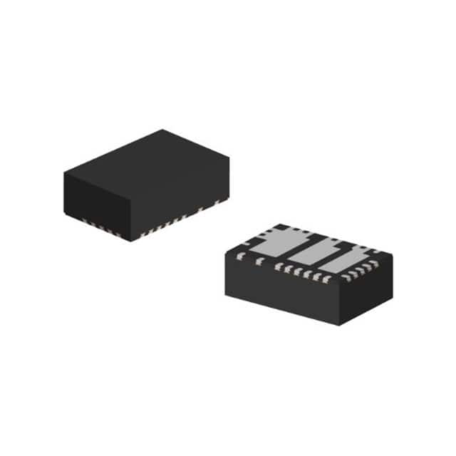
- Part No.:
- APM80950KNBATR
- Manufacturer:
- Allegro MicroSystems
- Category:
- LED Drivers
- Package:
- 32-PowerFQFN
- Datasheet:
-
 APM80950KNBATR.pdf
- Description:
- IC LED DRVR RGLTR PWM 1.5A 32QFN
- Quantity:
- Payment:

- Shipping:

Inventory:4,888
Please send an inquiry. Send us your inquiry, and we will respond immediately.
Product details
Overview
APM80950KNBATR from Allegro MicroSystems is a low-EMI, PWM-dimmable synchronous buck LED driver IC with integrated high-side and low-side MOSFETs, 1.5 A output current capability, 4.5–36 V input range, and QFN-32 package. It regulates LED current via external sense resistor and supports analog dimming (ADIM) and external PWM dimming.
For engineers reviewing the APM80950KNBATR datasheet, APM80950KNBATR pinout, APM80950KNBATR application, or APM80950KNBATR equivalent, key selection factors include its integrated SR FETs, dual dimming interface (PWM + ADIM), 100 mV/200 mV current-sense threshold selection via RNG pin, UVLO hysteresis (100–300 mV), and 40 V absolute max input rating.
Technical Context
The APM80950KNBATR implements a constant-current synchronous buck topology with internal high-side and low-side power MOSFETs, eliminating external switch requirements. It uses valley-current mode control with adaptive gate drive to optimize efficiency and EMI performance across wide input and load ranges.
Current regulation is achieved by comparing the voltage across an external sense resistor (RS1) to a programmable reference (100 mV or 200 mV) selected by the RNG pin logic level. The IC supports both analog dimming (via ADIM pin, 0.4–7 V input mapping to VCSREG) and external PWM dimming (via dedicated PWM pin with internal pull-down).
Key Specifications
| Parameter | Value and Actual Design Meaning |
|---|---|
| Max Output Current | 1.5 A - maximum regulated LED current with thermal derating; supports up to 1 A on demo board with 0.2 Ω Rs1 and RNG = VCC |
| Input Voltage Range | 4.5–36 V - operational range for automotive and industrial DC supplies; 40 V absolute max prevents damage during load dump |
| Current Sense Threshold | 100 mV or 200 mV - selectable via RNG pin; determines iLED = 0.1/Rsense or 0.2/Rsense, enabling flexible current scaling |
| UVLO Hysteresis | 100–300 mV - ensures stable startup/shutdown without oscillation during brown-in/brown-out conditions |
| Dimming Interfaces | PWM + ADIM - independent analog dimming (0.4–7 V) and external PWM (5–100% duty cycle) support hybrid dimming schemes |
| Package | QFN-32 (5 × 5 mm, 0.5 mm pitch) - thermally enhanced exposed pad for >1.5 A continuous operation with proper PCB copper |
Pinout & Package
APM80950KNBATR is housed in a 5 mm × 5 mm, 32-pin QFN package with exposed thermal pad (EP). Pin numbering follows standard counter-clockwise convention starting from top-left corner (Pin 1 = VOUT). The package supports reflow soldering per JEDEC J-STD-020.
| Pin/Terminal | Circuit Role | Design Meaning |
|---|---|---|
| VIN (Pins 5,6,7) | Power Input | High-current input path for 4.5–36 V supply; multiple pins reduce IR drop and improve thermal spreading |
| VOUT (Pins 1,2,3,4,30,31,32) | Switch Node / Output | SW node connection points; tie together externally to minimize loop inductance and EMI |
| PGND (Pins 8,9) | Power Ground | Low-impedance return path for high-frequency switching current; separate from SGND to avoid noise coupling |
| SGND (Pin 19) | Signal Ground | Analog reference for ADIM, FDSET, RNG, and internal error amplifier; must be routed away from PGND |
| RNG (Pin 17) | Current Range Select | Digital input selecting 100 mV (RNG = GND) or 200 mV (RNG = VCC) current-sense threshold |
| ADIM (Pin 14) | Analog Dimming Input | Voltage-controlled current reference: VCSREG = (VADIM – 0.4 V)/5; requires 0.4–7 V input |
| PWM (Pin 12) | PWM Dimming Input | Active-low dimming control; internal 10 kΩ pull-down enables default off-state when unconnected |
| EN (Pin 10) | Enable Input | Logic-level enable (1.8 V threshold); connects to VIN via jumper P1 on demo board for automatic startup |
| FDSET (Pin 13) | Foldback Delay Set | Resistor-to-ground sets overcurrent foldback delay time; protects against short-circuit events |
| FFn (Pin 15) | Frequency Foldback Enable | Enables frequency foldback below 4.3 V VVIN start threshold to maintain regulation during cold crank |
| CSH / CSL (Pins 22,21) | Current Sense High/Low | Inputs to internal current-sense amplifier; connect across external Rs1 for accurate iLED measurement |
| BOOT (Pin 24) | Bootstrap Supply | Charges high-side gate driver bootstrap capacitor; requires external 0.1 µF ceramic capacitor to SW |
| SW (Pins 26,28,29) | Switch Node | Internal high-side/low-side FET connection point; ties to VOUT pins and external inductor |
Key Features
| Feature | Design Value |
|---|---|
| Integrated SR FETs | Eliminates need for external high-side and low-side MOSFETs, reducing BOM count and layout complexity |
| Low-EMI Valley-Current Mode | Reduces peak switching current and dI/dt; enables compliance with CISPR-25 Class 5 radiated emissions limits |
| Dual Dimming Interface | Simultaneous support for analog (ADIM) and PWM dimming allows system-level flexibility and flicker-free operation |
| Programmable Current Threshold | RNG-selectable 100/200 mV sense voltage enables precise LED current tuning without changing Rs1 value |
| Cold-Crank Frequency Foldback | FFn-enabled frequency reduction below 4.3 V maintains regulation during automotive battery dips without output collapse |
Applications
| Automotive Headlamp Systems | Industrial LED Lighting |
|---|---|
Use Scenario: Adaptive front-lighting systems requiring precise, flicker-free dimming across wide battery voltage range (6–16 V). IC Role / Device Role / Timing Role: Constant-current LED driver with integrated FETs and cold-crank foldback for stable illumination during engine start. Use Value: Maintains 1.5 A LED current regulation down to 4.5 V input; RNG-selectable thresholds simplify calibration for multi-LED strings. | Use Scenario: High-reliability machine vision lighting where EMI must not interfere with camera sensor signals. IC Role / Device Role / Timing Role: Low-EMI buck controller driving high-power white LEDs in enclosed enclosures with minimal filtering. Use Value: Meets CISPR-25 Class 5 without external ferrite beads beyond demo-board configuration; reduces system-level EMI debug time. |
| Commercial Signage | Architectural Accent Lighting |
Use Scenario: Outdoor digital signage requiring PWM+analog hybrid dimming for smooth brightness transitions and ambient light adaptation. IC Role / Device Role / Timing Role: Dual-interface LED driver supporting 0–100% analog dimming and 100–1000 Hz PWM for seamless intensity control. Use Value: ADIM pin accepts 0.4–7 V input for linear current scaling; PWM pin tolerates 3.3 V/5 V logic without level shifters. | Use Scenario: RGBW architectural lighting where thermal management and compact form factor are critical in tight mounting spaces. IC Role / Device Role / Timing Role: Thermally optimized QFN-32 LED driver delivering 1.5 A in <5 mm² footprint with exposed EP for direct heatsink attachment. Use Value: Exposed thermal pad enables >1.2 A continuous current at 70°C ambient with 2 oz copper; eliminates need for external FET thermal islands. |
Equivalent & Alternatives
The following parts are listed as comparable options for similar LED driver applications.
| Alternative Part | Technical Difference | Application Difference | Selection Advice |
|---|---|---|---|
| MPQ4425AGU-AEC1-P | 40 V max input, 2 A output, no integrated low-side FET; requires external sync rectifier | Lacks ADIM interface; PWM-only dimming; AEC-Q100 qualified but no cold-crank foldback | Choose for higher current needs where external FET layout is acceptable and analog dimming is unnecessary |
| LM3409HVMM/NOPB | 40 V max input, 5 A capable, external MOSFET driver; no integrated FETs or ADIM pin | Requires full external power stage; supports only PWM and resistor-based current setting; no frequency foldback | Choose for ultra-high-current (>2 A) or high-voltage (>36 V) LED strings where discrete control is preferred |
Compared with MPQ4425AGU-AEC1-P and LM3409HVMM/NOPB, the APM80950KNBATR delivers integrated SR FETs, dual dimming (PWM + ADIM), and cold-crank foldback in a single QFN-32 package-reducing component count by ≥6 devices and enabling sub-5 mm² solutions for space-constrained LED modules.
Availability
APM80950KNBATR is available at Aetrix Electronics and suitable for automotive headlamps, industrial machine vision lighting, and commercial signage requiring stable component supply, long-term lifecycle support, and AEC-Q100-aligned reliability.
Supply support for APM80950KNBATR includes scheduled delivery planning, volume procurement assistance, BOM continuity management, traceable sourcing, and lifecycle availability coordination for OEM customers, industrial embedded developers, connected-device designers, and electronics production programs.
Manufacturer
Allegro MicroSystems is a U.S.-based designer of high-performance Hall-effect sensors, motor drivers, and power ICs, headquartered in Manchester, NH, with global manufacturing and support.
The APM80950 product line targets automotive and industrial LED lighting applications demanding low EMI, high integration, and robust operation across wide input voltage and temperature ranges.
FAQ
What is the recommended current-sense resistor value for 1.5 A LED output with APM80950KNBATR?
For 1.5 A output using the 200 mV current-sense threshold (RNG = VCC), the recommended Rsense is 0.133 Ω (200 mV / 1.5 A). The APM80950KNBATR datasheet specifies 0.2 Ω for 1 A on the demo board; scaling linearly yields 0.133 Ω. Use 1% tolerance, 0.5 W or higher power-rated resistors with low TCR for stability. The APM80950KNBATR supports this value directly without recalibration.
Does APM80950KNBATR support analog dimming without external components?
Yes, APM80950KNBATR supports analog dimming via its ADIM pin with no external op-amps or DACs required. Apply 0.4–7 V to ADIM to set VCSREG = (VADIM – 0.4 V)/5, which linearly scales LED current. The APM80950KNBATR includes internal reference and amplifier circuitry-only a clean voltage source (e.g., MCU DAC or potentiometer) is needed. Do not leave ADIM floating; tie to GND via 100 kΩ if unused.
How does the RNG pin affect LED current regulation in APM80950KNBATR?
The RNG pin on APM80950KNBATR selects between two fixed current-sense thresholds: 100 mV (RNG = GND) or 200 mV (RNG = VCC). This changes the gain of the current regulation equation from iLED = 0.1/Rsense to iLED = 0.2/Rsense. For example, with Rsense = 0.2 Ω, RNG = VCC gives 1 A output, while RNG = GND gives 0.5 A. The APM80950KNBATR uses this to enable dual-range current programming without changing hardware.
Can APM80950KNBATR operate during automotive cold-crank conditions?
Yes, APM80950KNBATR supports cold-crank operation down to 4.3 V input via its FFn pin–enabled frequency foldback. When VVIN falls below 4.3 V, the APM80950KNBATR reduces switching frequency to maintain regulation and prevent output collapse. This behavior is confirmed in the user manual's "CONFIGURATIONS" section and validated on the demo board under 6 V input with 0.5 A load. No external circuitry is required to activate this feature.
What thermal design considerations apply to APM80950KNBATR in QFN-32 package?
The APM80950KNBATR QFN-32 package features an exposed thermal pad (EP) that must be soldered to ≥4 cm² of 2 oz copper on the PCB for 1.5 A continuous operation at 70°C ambient. Thermal vias (≥8 × 0.3 mm) under the EP are mandatory to transfer heat to inner/ground layers. The APM80950KNBATR datasheet specifies θJA ≈ 35°C/W with proper layout; insufficient copper or missing vias will cause thermal shutdown above 1.2 A. Avoid routing signal traces under the EP area.
APM80950KNBATR Specifications
- Product attributes
- Attribute value
- Manufacturer:
- Allegro MicroSystems
- Series:
- -
- Package/Case:
- 32-PowerFQFN
- Packaging:
- Tape & Reel (TR)
- Product Status:
- Obsolete
- Type:
- DC DC Regulator
- Topology:
- Buck
- Internal Switch(s):
- Yes
- Number of Outputs:
- 1
- Voltage - Supply (Min):
- 4.5V
- Voltage - Supply (Max):
- 36V
- Voltage - Output:
- 5V
- Current - Output / Channel:
- 1.5A
- Frequency:
- 2MHz
- Dimming:
- PWM
- Applications:
- -
- Operating Temperature:
- -40°C ~ 150°C (TJ)
- Grade:
- Automotive
- Qualification:
- AEC-Q100
- Mounting Type:
- Surface Mount, Wettable Flank
- Supplier Device Package:
- 32-QFN (4x6)
APM80950KNBATR FAQ
1.How can I place an order for APM80950KNBATR through Aetrix?
Please submit a Request for Quotation (RFQ) for APM80950KNBATR on Aetrix. Our sales agent will provide a competitive quotation and guide you through the order confirmation once you accept the terms.
2.Are the price and stock information for APM80950KNBATR reliable?
The price and inventory of APM80950KNBATR are updated periodically and may fluctuate due to market conditions. Stock and pricing data are typically refreshed every 24 hours. Quotation validity for APM80950KNBATR is usually 5 days.
3.What payment methods are accepted for APM80950KNBATR?
We accept Wire Transfer, PayPal, Credit Card, Western Union, MoneyGram, and Escrow for APM80950KNBATR transactions.
Note: Certain payment methods may incur a processing fee.
4.How is shipping managed for APM80950KNBATR?
APM80950KNBATR orders can be shipped via leading logistics carriers, including DHL, UPS, FedEx, TNT, or Registered Mail.
Once your APM80950KNBATR order is processed, you will receive an email with the shipment details and tracking number.
Note: Tracking information may take up to 24 hours to appear. Express delivery typically takes 3–5 business days.
5.How can I obtain technical support or documentation for APM80950KNBATR?
For technical support, including APM80950KNBATR datasheets, pinout diagrams, or application guidance, please contact our engineering support team. They can provide detailed documentation and assistance for your APM80950KNBATR requirements.
6.How does Aetrix verify that APM80950KNBATR is sourced from the original manufacturer or authorized distributors?
All APM80950KNBATR products on Aetrix are procured from qualified distributors and authorized channels. Our dedicated quality assurance team conducts strict verification, including traceability checks and, if necessary, third-party testing. This ensures that APM80950KNBATR meets industry standards.
7.What is the process for return or replacement of APM80950KNBATR?
All APM80950KNBATR units undergo pre-shipment inspection (PSI). If there is an issue with APM80950KNBATR, returns or replacements are accepted under the following conditions:
1.Quantity discrepancies, incorrect items, or visible external defects (such as breakage or corrosion), acknowledged by Aetrix.
2.The issue is reported within 90 days of delivery.
3.The APM80950KNBATR part is unused and in its original packaging.
Return procedure for APM80950KNBATR:
1.Submit a request within 90 days.
2.Obtain a Return Material Authorization (RMA) from Aetrix.
APM80950KNBATR Tags

-
BCR402RE6327HTSA1
Infineon Technologies

-
BCR430UXTSA2
Infineon Technologies

-
BCR420UE6433HTMA1
Infineon Technologies
-
BCR420UE6327HTSA1
Infineon Technologies
-
BCR421UE6327HTSA1
Infineon Technologies

-
LYT1604D-TL
Power Integrations

-
HV9910CLG-G
Microchip Technology

-
CL2N8-G
Microchip Technology

-
BCR420UW6-7
Diodes Incorporated
-
BCR421UW6-7
Diodes Incorporated

-
BCR420UFD-7
Diodes Incorporated
-
BCR421UFD-7
Diodes Incorporated
Tech Hub

A practical engineering and sourcing framework covering lifecycle verification, lifetime-buy calculations, replacement qualification, supplier checks and counterfeit-risk controls.

TTL and CMOS logic families differ in thresholds, loading, output drive, power and timing. This engineering guide compares 74HC and 74HCT, calculates noise margins and checks 3.3 V/5 V compatibility.

A practical engineering guide to 3.3V and 5V logic compatibility, input thresholds, resistor dividers, translator ICs, MOSFET level shifting, I2C pull-ups, timing limits and power-sequencing risks.

The 74HC595 uses push-pull logic outputs, while the TPIC6B595 uses 50 V open-drain DMOS sinks for higher-power loads. This guide compares timing, current limits, 3.3 V interfacing, load wiring, thermal…

The 74HC595 converts serial data into eight stable parallel outputs. This guide covers pin functions, shift and storage timing, OE and MR behavior, drive-current limits, cascading, voltage compatibilit…

A technical comparison of level-sensitive latches and edge-triggered flip-flops, covering timing windows, setup and hold limits, master–slave operation, time borrowing, race-through, HDL inference and…

A D latch stores one bit while Enable controls when data can pass. This reference covers gate-level operation, truth tables, transparency, setup and hold timing, LE versus OE, common ICs and practical …

An SR latch stores one bit through cross-coupled feedback. This engineering reference covers NOR and NAND implementations, truth tables, forbidden-state recovery, gated operation, switch debouncing, fa…

Latch circuits retain one bit through feedback. This technical reference covers SR and D latches, truth tables, transparency, timing limits, latch-versus-flip-flop behavior, applications and common log…

An engineering guide to LED driver operation, constant-current and constant-voltage outputs, linear and switching topologies, dimming, IC selection, calculations, replacement compatibility, and fault c…


