
 My Inquiry
 My Account


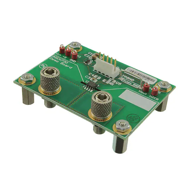
Allegro MicroSystems ASEK730KLC-40AB-T-DK
- Part No.:
- ASEK730KLC-40AB-T-DK
- Manufacturer:
- Allegro MicroSystems
- Category:
- Sensor Evaluation Boards
- Package:
- Datasheet:
-
 ASEK730KLC-40AB-T-DK.pdf
- Description:
- EVAL BOARD FOR ACS730
- Quantity:
- Payment:

- Shipping:

Inventory:2,075
Please send an inquiry. Send us your inquiry, and we will respond immediately.
Product details
Overview
ASEK730KLC-40AB-T-DK from Allegro MicroSystems is a galvanically isolated, bidirectional current sensor IC in an 8-pin SOIC package, delivering 1 MHz bandwidth, ±40 A sensing range, 50 mV/A sensitivity, 5 V single-supply operation, and 1.2 mΩ primary conductor resistance for low-loss high-current monitoring in motor drives and power converters.
For engineers reviewing the ASEK730KLC-40AB-T-DK datasheet, ASEK730KLC-40AB-T-DK pinout, ASEK730KLC-40AB-T-DK application, or ASEK730KLC-40AB-T-DK equivalent, key selection criteria include isolation rating (2400 VRMS), temperature-stable offset (±20 mV over –40°C to 125°C), total output error (±5% at full scale), and compatibility with space-constrained PCB layouts requiring basic isolation per UL 62368-1.
Technical Context
The ASEK730KLC-40AB-T-DK integrates a linear Hall sensor with a low-resistance copper conduction path (pins 1–4) magnetically coupled to signal terminals (pins 5–8), enabling high-side current sensing without external isolation. Its proprietary amplifier and filter design achieves 1 MHz small-signal bandwidth while maintaining 40 µA/√Hz input-referred noise density.
Patented digital temperature compensation corrects sensitivity and offset drift across –40°C to 125°C, and an integrated magnetic shield minimizes capacitive coupling from dV/dt transients on the primary conductor. The device outputs a ratiometric analog voltage (VIOUT) centered at 2.5 V at zero current, referenced to VZCR.
Key Specifications
| Parameter | Value and Actual Design Meaning |
|---|---|
| Sensing Range | ±40 A - supports bidirectional DC/AC current measurement in inverters and servo drives without polarity reversal circuitry |
| Sensitivity | 50 mV/A - enables direct ADC interfacing with 12-bit resolution over full range using standard 3.3 V or 5 V reference |
| Bandwidth | 1 MHz - captures fast transient currents in SiC/GaN-based switching systems up to 500 kHz PWM frequencies |
| Primary Resistance | 1.2 mΩ - limits power loss to <1.92 W at 40 A, reducing thermal stress in high-current bus bars |
| Isolation Rating | 2400 VRMS - certified for 60 s per UL 62368-1, supporting basic isolation in industrial mains-connected equipment |
| Total Output Error | ±5% - includes sensitivity, offset, and nonlinearity contributions across full temperature range, enabling accurate closed-loop control |
| Supply Voltage | 4.5–5.5 V - compatible with standard 5 V rail; PSRR of 35 dB suppresses supply ripple in noisy SMPS environments |
Pinout & Package
The ASEK730KLC-40AB-T-DK is housed in an 8-pin SOICN (Small Outline Integrated Circuit, Narrow) package with gull-wing leads, 100% matte tin plating, and RoHS-compliant Pb-based solder bumps (per "-T" suffix). Creepage and clearance are ≥4 mm; distance through insulation is 44 µm.
| Pin/Terminal | Circuit Role | Design Meaning |
|---|---|---|
| 1, 2 (IP+) | Primary current input | Fused internal copper path for high-current sensing; connects to high-side or low-side bus; 1.2 mΩ resistance |
| 3, 4 (IP–) | Primary current return | Completes current path; electrically isolated from signal pins; rated for 2400 VRMS working voltage |
| 5 (GND) | Signal ground reference | Reference node for VIOUT and VZCR; must be connected to system signal ground, not power ground |
| 6 (VZCR) | Zero-current reference output | Provides stable 2.5 V DC reference matching VIOUT quiescent level; used for differential measurement or offset cancellation |
| 7 (VIOUT) | Analog current-proportional output | 0.5–4.5 V swing for ±40 A range; 2.5 V at IP = 0 A; slew rate 2.67 V/µs supports fast transient response |
| 8 (VCC) | Power supply input | 5 V ±10% supply; draws 17–25 mA; includes internal regulator and POR circuitry |
Key Features
| Feature | Design Value |
|---|---|
| Galvanic isolation | 2400 VRMS withstand, 420 VPK working voltage, and 4 mm creepage/clearance meet UL 62368-1 basic insulation requirements |
| Digital temperature compensation | Corrects sensitivity and offset drift across –40°C to 125°C, reducing total error to ±5% without external calibration |
| Integrated magnetic shield | Eliminates capacitive coupling from high dV/dt transients on IP path, ensuring stable output during fast-switching events |
| Low primary resistance | 1.2 mΩ conduction path minimizes I²R losses and thermal rise, enabling continuous 40 A operation in compact layouts |
| VZCR reference output | Provides matched 2.5 V reference to VIOUT at zero current, enabling ratiometric measurement and common-mode rejection |
Applications
| Motor Control | Switched-Mode Power Supply |
|---|---|
Use Scenario: Real-time phase current monitoring in three-phase BLDC or PMSM motor drives using field-oriented control (FOC). IC Role / Device Role / Timing Role: High-bandwidth (1 MHz), isolated current feedback sensor placed on inverter leg low-side or high-side bus. Use Value: Enables precise torque regulation and overcurrent protection with <0.7 µs response time and ±5% total error across operating temperature. | Use Scenario: Input/output current sensing in 1–5 kW telecom rectifiers and server PSUs with SiC MOSFETs switching at >200 kHz. IC Role / Device Role / Timing Role: Isolated primary-side current monitor for peak-current-mode control and cycle-by-cycle fault limiting. Use Value: 1.2 mΩ resistance avoids heatsinking; 1 MHz bandwidth captures switching harmonics; 2400 VRMS isolation meets safety standards. |
| Overcurrent Protection | Energy Metering Interface |
Use Scenario: Fast-trip detection in industrial circuit breakers and solid-state relays protecting 40 A distribution lines. IC Role / Device Role / Timing Role: Primary conductor current sensor feeding comparator or microcontroller ADC for sub-microsecond fault response. Use Value: 0.2 µs propagation delay and 0.7 µs response time enable <1 µs trip latency; galvanic isolation eliminates level-shifting components. | Use Scenario: Secondary-side current sampling in DIN-rail energy meters measuring grid-connected solar inverters up to 40 A. IC Role / Device Role / Timing Role: Isolated analog front-end sensor converting line current to calibrated voltage for metrology ADC. Use Value: Factory-trimmed sensitivity (±1.5% typical) and lifetime drift compensation (±6.7% total error including aging) ensure long-term meter accuracy. |
Equivalent & Alternatives
The following parts are listed as comparable options for similar current sensing applications.
| Alternative Part | Technical Difference | Application Difference | Selection Advice |
|---|---|---|---|
| ACS37030 | Higher bandwidth (1.5 MHz), lower noise (25 µA/√Hz), but ±30 A range and no VZCR output | Preferred for ultra-fast transient capture in GaN-based converters; lacks differential reference for ratiometric use | Select ACS37030 when bandwidth >1 MHz and noise <30 µA/√Hz are critical; avoid if VZCR-referenced measurement is required |
| CT428 | Open-loop architecture, ±50 A range, 40 mV/A sensitivity, no integrated temperature compensation | Better suited for cost-sensitive, lower-accuracy applications where ambient temperature stays near 25°C | Choose CT428 for new designs prioritizing BOM cost over wide-temperature accuracy; not recommended for automotive or industrial extremes |
Compared with ASEK730KLC-40AB-T-DK, ACS37030 offers superior speed and noise performance but sacrifices ratiometric referencing and full-range accuracy over temperature, while CT428 provides higher current range at lower cost but requires external calibration for stable operation beyond 25°C.
Availability
ASEK730KLC-40AB-T-DK is available at Aetrix Electronics and suitable for motor control, switched-mode power supplies, overcurrent fault protection, and energy metering requiring stable component supply and long-term lifecycle support.
Supply support for ASEK730KLC-40AB-T-DK includes scheduled delivery planning, volume procurement assistance, BOM continuity management, traceable sourcing, and lifecycle availability coordination for OEM customers, industrial embedded developers, connected-device designers, and electronics production programs.
Manufacturer
Allegro MicroSystems is a U.S.-based designer and manufacturer of high-performance magnetic sensing and power IC solutions, specializing in Hall-effect sensors, current sensors, and motor driver ICs.
The ACS730 family was engineered for high-accuracy, galvanically isolated current sensing in industrial and commercial power systems, emphasizing bandwidth, thermal stability, and ease of integration in space-constrained PCBs.
FAQ
What is the maximum continuous current rating for ASEK730KLC-40AB-T-DK?
The ASEK730KLC-40AB-T-DK is rated for ±40 A continuous primary current at TA = 25°C. Derating applies above 25°C ambient; junction temperature must remain ≤165°C. At 125°C ambient, continuous current is limited to approximately ±25 A based on thermal modeling of the 1.2 mΩ conduction path and package thermal resistance.
Does ASEK730KLC-40AB-T-DK require external filtering capacitors?
Yes, ASEK730KLC-40AB-T-DK requires a 0.1 µF bypass capacitor between VCC and GND (CBYPASS), and a 1 nF capacitor between VZCR and GND (CVZCR), as specified in the functional schematic. These capacitors stabilize the internal regulator and suppress high-frequency noise on the reference output, directly impacting measurement accuracy and bandwidth fidelity.
How does the VZCR pin improve measurement accuracy in ASEK730KLC-40AB-T-DK?
The VZCR pin in ASEK730KLC-40AB-T-DK provides a buffered 2.5 V reference that matches the VIOUT quiescent voltage at zero current. When used differentially (e.g., VIOUT – VZCR), it cancels common-mode offset drift and supply variations, improving effective resolution and long-term stability-especially critical in precision current loops where absolute zero-current accuracy matters.
Is ASEK730KLC-40AB-T-DK suitable for high-voltage DC applications like EV battery monitoring?
No-ASEK730KLC-40AB-T-DK is rated for basic isolation only (420 VPK working voltage per UL 62368-1), making it unsuitable for direct connection to >400 V DC battery buses. It is designed for secondary-side or auxiliary power rail monitoring in EV chargers and onboard converters, not primary traction battery current sensing which requires reinforced isolation.
What does the "-T" suffix indicate in ASEK730KLC-40AB-T-DK?
The "-T" suffix in ASEK730KLC-40AB-T-DK denotes Pb-based solder bumps manufactured under RoHS exemptions (Annex III/IV, exemptions 7(a), 15, 15a). Electrical and thermal performance is identical to "-S" variants; the distinction is solely in solder composition and regulatory compliance path-not functionality, reliability, or pinout.
ASEK730KLC-40AB-T-DK Specifications
- Product attributes
- Attribute value
- Manufacturer:
- Allegro MicroSystems
- Series:
- -
- Packaging:
- Bulk
- Product Status:
- Not For New Designs
- Sensor Type:
- Current Sensor
- Sensing Range:
- 40A
- Interface:
- Analog
- Sensitivity:
- 50mV/A
- Voltage - Supply:
- 4.5V ~ 5.5V
- Embedded:
- -
- Contents:
- Board(s)
- Utilized IC / Part:
- ACS730
ASEK730KLC-40AB-T-DK FAQ
1.How can I place an order for ASEK730KLC-40AB-T-DK through Aetrix?
Please submit a Request for Quotation (RFQ) for ASEK730KLC-40AB-T-DK on Aetrix. Our sales agent will provide a competitive quotation and guide you through the order confirmation once you accept the terms.
2.Are the price and stock information for ASEK730KLC-40AB-T-DK reliable?
The price and inventory of ASEK730KLC-40AB-T-DK are updated periodically and may fluctuate due to market conditions. Stock and pricing data are typically refreshed every 24 hours. Quotation validity for ASEK730KLC-40AB-T-DK is usually 5 days.
3.What payment methods are accepted for ASEK730KLC-40AB-T-DK?
We accept Wire Transfer, PayPal, Credit Card, Western Union, MoneyGram, and Escrow for ASEK730KLC-40AB-T-DK transactions.
Note: Certain payment methods may incur a processing fee.
4.How is shipping managed for ASEK730KLC-40AB-T-DK?
ASEK730KLC-40AB-T-DK orders can be shipped via leading logistics carriers, including DHL, UPS, FedEx, TNT, or Registered Mail.
Once your ASEK730KLC-40AB-T-DK order is processed, you will receive an email with the shipment details and tracking number.
Note: Tracking information may take up to 24 hours to appear. Express delivery typically takes 3–5 business days.
5.How can I obtain technical support or documentation for ASEK730KLC-40AB-T-DK?
For technical support, including ASEK730KLC-40AB-T-DK datasheets, pinout diagrams, or application guidance, please contact our engineering support team. They can provide detailed documentation and assistance for your ASEK730KLC-40AB-T-DK requirements.
6.How does Aetrix verify that ASEK730KLC-40AB-T-DK is sourced from the original manufacturer or authorized distributors?
All ASEK730KLC-40AB-T-DK products on Aetrix are procured from qualified distributors and authorized channels. Our dedicated quality assurance team conducts strict verification, including traceability checks and, if necessary, third-party testing. This ensures that ASEK730KLC-40AB-T-DK meets industry standards.
7.What is the process for return or replacement of ASEK730KLC-40AB-T-DK?
All ASEK730KLC-40AB-T-DK units undergo pre-shipment inspection (PSI). If there is an issue with ASEK730KLC-40AB-T-DK, returns or replacements are accepted under the following conditions:
1.Quantity discrepancies, incorrect items, or visible external defects (such as breakage or corrosion), acknowledged by Aetrix.
2.The issue is reported within 90 days of delivery.
3.The ASEK730KLC-40AB-T-DK part is unused and in its original packaging.
Return procedure for ASEK730KLC-40AB-T-DK:
1.Submit a request within 90 days.
2.Obtain a Return Material Authorization (RMA) from Aetrix.
ASEK730KLC-40AB-T-DK Tags
-
1782
Adafruit Industries LLC
-
SEN0142
DFRobot

-
2857
Adafruit Industries LLC
-
3316
Adafruit Industries LLC
-
2652
Adafruit Industries LLC
-
3317
Adafruit Industries LLC
-
163
Adafruit Industries LLC
-
SEN-09269
SparkFun Electronics
-
3709
Adafruit Industries LLC
-
1018
Adafruit Industries LLC
-
VL53L5CX-SATEL
STMicroelectronics
-
3387
Adafruit Industries LLC
Tech Hub

A practical engineering and sourcing framework covering lifecycle verification, lifetime-buy calculations, replacement qualification, supplier checks and counterfeit-risk controls.

TTL and CMOS logic families differ in thresholds, loading, output drive, power and timing. This engineering guide compares 74HC and 74HCT, calculates noise margins and checks 3.3 V/5 V compatibility.

A practical engineering guide to 3.3V and 5V logic compatibility, input thresholds, resistor dividers, translator ICs, MOSFET level shifting, I2C pull-ups, timing limits and power-sequencing risks.

The 74HC595 uses push-pull logic outputs, while the TPIC6B595 uses 50 V open-drain DMOS sinks for higher-power loads. This guide compares timing, current limits, 3.3 V interfacing, load wiring, thermal…

The 74HC595 converts serial data into eight stable parallel outputs. This guide covers pin functions, shift and storage timing, OE and MR behavior, drive-current limits, cascading, voltage compatibilit…

A technical comparison of level-sensitive latches and edge-triggered flip-flops, covering timing windows, setup and hold limits, master–slave operation, time borrowing, race-through, HDL inference and…

A D latch stores one bit while Enable controls when data can pass. This reference covers gate-level operation, truth tables, transparency, setup and hold timing, LE versus OE, common ICs and practical …

An SR latch stores one bit through cross-coupled feedback. This engineering reference covers NOR and NAND implementations, truth tables, forbidden-state recovery, gated operation, switch debouncing, fa…

Latch circuits retain one bit through feedback. This technical reference covers SR and D latches, truth tables, transparency, timing limits, latch-versus-flip-flop behavior, applications and common log…

An engineering guide to LED driver operation, constant-current and constant-voltage outputs, linear and switching topologies, dimming, IC selection, calculations, replacement compatibility, and fault c…


