
 My Inquiry
 My Account


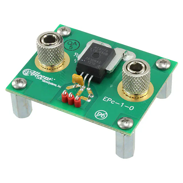
Allegro MicroSystems ASEK770ECB-200B-T-DK
- Part No.:
- ASEK770ECB-200B-T-DK
- Manufacturer:
- Allegro MicroSystems
- Category:
- Sensor Evaluation Boards
- Package:
- Datasheet:
-
 ASEK770ECB-200B-T-DK.pdf
- Description:
- BOARD DEMO 770ECB-200B SENSOR
- Quantity:
- Payment:

- Shipping:

Inventory:4,706
Please send an inquiry. Send us your inquiry, and we will respond immediately.
Product details
Overview
ASEK770ECB-200B-T-DK from Allegro MicroSystems is a thermally enhanced, galvanically isolated, bidirectional Hall-effect current sensor IC with 100 µΩ internal conductor resistance, ±200 A primary current range, 10 mV/A sensitivity, and 120 kHz bandwidth. It delivers ratiometric analog output voltage centered at VCC/2 for precise AC/DC current sensing in high-side, high-voltage motor control and inverter applications.
For engineers reviewing the ASEK770ECB-200B-T-DK datasheet, ASEK770ECB-200B-T-DK pinout, ASEK770ECB-200B-T-DK application, or ASEK770ECB-200B-T-DK equivalent, key selection criteria include its ±200 A bidirectional range, 3 mV noise floor, –40°C to +85°C operating temperature, UL-certified 4800 VRMS isolation, and factory-trimmed total output error of ±0.5% at 25°C.
Technical Context
The ASEK770ECB-200B-T-DK integrates a chopper-stabilized BiCMOS Hall IC with proprietary digital temperature compensation for offset and sensitivity across –40°C to +85°C. Its copper conduction path (pins 4–5) is magnetically coupled to the Hall die via low-hysteresis core, enabling high-accuracy current-to-voltage conversion without external shunts.
Allegro's integrated shield technology suppresses capacitive coupling from high dV/dt current paths, ensuring stable offset in high-side configurations. The device features undervoltage lockout (3.8 V rising threshold), 4.1 µs rise time, and 2.4 µs propagation delay - optimized for real-time overcurrent fault detection in power converters.
Key Specifications
| Parameter | Value and Actual Design Meaning |
|---|---|
| Primary Current Range | ±200 A - supports bidirectional measurement of high-power motor phase currents or DC bus currents without polarity reversal wiring. |
| Sensitivity | 10 mV/A typical - yields 2.0 V full-scale output swing (±200 A × 10 mV/A) on 5 V supply, enabling direct ADC interfacing with >12-bit resolution. |
| Bandwidth | 120 kHz - captures fast transient currents in PWM-driven inverters and switch-mode power supplies up to 20 kHz switching frequencies. |
| Isolation Rating | 4800 VRMS withstand (UL 62368-1) - enables safe integration into 1000 VDC systems with reinforced isolation compliance. |
| Total Output Error | ±0.5% at TA = 25°C - includes nonlinearity, offset, and sensitivity errors; ensures <±1 A absolute accuracy at ±200 A full scale. |
| Noise | 3 mV peak-to-peak (±3σ) - low enough to resolve sub-ampere current changes in precision load monitoring. |
| Conductor Resistance | 100 µΩ typical - dissipates only 4 W at 200 A (I²R), minimizing thermal impact and system efficiency loss. |
Pinout & Package
ASEK770ECB-200B-T-DK uses a thermally enhanced 5-pin CB package (leadform PFF) with isolated current path terminals and signal pins. The package features 6.9 mm creepage/clearance and 400 µm distance through insulation for UL-certified basic and reinforced isolation.
| Pin/Terminal | Circuit Role | Design Meaning |
|---|---|---|
| 1 | VCC | 5 V ±0.5 V supply input; powers Hall IC and signal chain; includes undervoltage lockout at 3.8 V. |
| 2 | GND | Signal reference ground; electrically isolated from current path; must be connected to controller ground plane. |
| 3 | VIOUT | Analog output (0.5–4.5 V); ratiometric to VCC; quiescent level = VCC/2 for bidirectional mode; drives 4.7 kΩ min load. |
| 4 | IP+ | High-side current input terminal; connects to power rail or phase leg; part of 100 µΩ copper conduction path. |
| 5 | IP– | Current return terminal; completes isolated conduction path; electrically isolated from all signal pins (1–3). |
Key Features
| Feature | Design Value |
|---|---|
| Digital temperature compensation | Proprietary piecewise linear algorithm corrects offset and sensitivity drift across –40°C to +85°C, maintaining ±1.5% total error over full range. |
| Integrated magnetic shield | Reduces capacitive coupling from high dV/dt current paths, eliminating offset drift in 1000 VDC high-side sensing applications. |
| Galvanic isolation | 4800 VRMS isolation rating eliminates need for optocouplers or isolated amplifiers in high-voltage systems. |
| Low-loss conductor | 100 µΩ internal resistance limits power dissipation to 4 W at 200 A, enabling compact thermal design without external heatsinking. |
| Fast response | 4.1 µs rise time and 2.4 µs propagation delay support real-time overcurrent protection in IGBT/SiC inverter gate drivers. |
Applications
| Motor Phase Current Sensing | Inverter DC Bus Monitoring |
|---|---|
|
Use Scenario: Real-time measurement of three-phase motor winding currents in servo drives and EV traction inverters. IC Role / Device Role / Timing Role: Bidirectional current sensor providing analog feedback to FOC (Field-Oriented Control) processor at 10–20 kHz update rate. Use Value: ±200 A range and 120 kHz bandwidth capture full PWM current waveform harmonics; 100 µΩ conductor minimizes I²R heating in space-constrained motor control PCBs. |
Use Scenario: Continuous monitoring of high-current DC link in solar string inverters and UPS systems. IC Role / Device Role / Timing Role: High-side isolated current monitor feeding ADC for energy metering and overcurrent shutdown logic. Use Value: 4800 VRMS isolation enables direct connection to 1000 VDC bus; ±0.5% error ensures accurate power calculation and battery state-of-charge estimation. |
| Industrial Power Supply Protection | EV Onboard Charger (OBC) Control |
|
Use Scenario: Secondary-side current sensing in high-efficiency 3 kW telecom rectifiers and industrial SMPS units. IC Role / Device Role / Timing Role: Precision current feedback element in digitally controlled LLC resonant converter regulation loop. Use Value: 3 mV noise floor resolves <±0.3 A changes at 200 A full scale; ratiometric output rejects supply ripple, improving regulation stability. |
Use Scenario: Input AC line current and output DC charging current monitoring in bi-directional OBC modules. IC Role / Device Role / Timing Role: Dual-role sensor supporting both grid-tie and vehicle-to-grid (V2G) operation with bidirectional ±200 A capability. Use Value: Factory-trimmed ±0.5% accuracy meets IEC 62955 leakage current detection requirements; AEC-Q100 qualification ensures automotive reliability. |
Equivalent & Alternatives
The following parts are listed as comparable options for similar bidirectional current sensing applications.
| Alternative Part | Technical Difference | Application Difference | Selection Advice |
|---|---|---|---|
| ACS772LCB-200B-PFF-T | Same 5-pin CB package and ±200 A range, but rated for –40°C to +150°C and features 15 mV/A sensitivity (higher output swing). | Targeted at under-hood automotive applications requiring extended temperature range; not UL-certified for reinforced isolation. | Select ACS772LCB-200B-PFF-T when junction temperature exceeds 85°C or higher output voltage swing is needed; ASEK770ECB-200B-T-DK preferred for UL-compliant industrial systems. |
| TMCS1108A4UQDR | TI's 8-pin SOIC with ±200 A range, 400 mV/A sensitivity, and 200 kHz bandwidth; uses fluxgate sensing instead of Hall effect. | Higher bandwidth and lower noise (1.2 mV), but requires external 5 V supply and lacks integrated isolation barrier certification. | Select TMCS1108A4UQDR for ultra-low-noise, high-bandwidth applications where external isolation components are acceptable; ASEK770ECB-200B-T-DK provides certified isolation and simpler BOM. |
Compared with ACS772LCB-200B-PFF-T and TMCS1108A4UQDR, ASEK770ECB-200B-T-DK uniquely combines UL-certified 4800 VRMS isolation, factory-trimmed ±0.5% accuracy at 25°C, and 100 µΩ conductor loss in a single-component solution - reducing system-level validation effort and PCB area in industrial and grid-tied applications.
Availability
ASEK770ECB-200B-T-DK is available at Aetrix Electronics and suitable for motor control, inverter DC bus monitoring, and industrial power supply protection requiring stable component supply, long-term lifecycle support, and UL-certified isolation performance.
Supply support for ASEK770ECB-200B-T-DK includes scheduled delivery planning, volume procurement assistance, BOM continuity management, traceable sourcing, and lifecycle availability coordination for OEM customers, industrial embedded developers, connected-device designers, and electronics production programs.
Manufacturer
Allegro MicroSystems is a U.S.-based semiconductor company specializing in magnetic sensing and power ICs, with decades of expertise in Hall-effect current sensors for automotive and industrial markets.
The ACS770 family was designed for high-precision, isolated current sensing in demanding power electronics applications - emphasizing low conductor loss, wide temperature stability, and regulatory-certified safety isolation.
FAQ
What is the maximum continuous current rating for ASEK770ECB-200B-T-DK?
The ASEK770ECB-200B-T-DK is rated for ±200 A primary sampled current under continuous operation at ambient temperatures up to +85°C. Its 100 µΩ internal conductor resistance results in only 4 W of power dissipation at full scale, enabling reliable operation without forced air cooling in properly designed PCB layouts with adequate copper area.
Does ASEK770ECB-200B-T-DK require external calibration after soldering?
No, ASEK770ECB-200B-T-DK is fully calibrated at the factory and requires no end-user calibration. Its proprietary digital temperature compensation maintains accuracy across –40°C to +85°C, and the quiescent output voltage is trimmed to VCC/2 ±4 mV at 25°C - eliminating post-assembly offset adjustment in most applications.
Can ASEK770ECB-200B-T-DK be used in high-side configurations above 400 VDC?
Yes, ASEK770ECB-200B-T-DK is UL-certified for 4800 VRMS isolation and approved for 1358 VPK working voltage under basic isolation (UL 62368-1). Its integrated shield technology prevents offset drift from high dV/dt signals, making it suitable for direct high-side sensing in 600–1000 VDC systems such as solar inverters and EV chargers.
What is the recommended bypass capacitor for ASEK770ECB-200B-T-DK?
A 0.1 µF ceramic capacitor (CBYP) is required between VCC and GND, placed as close as possible to pins 1 and 2. This stabilizes the internal regulator and reduces supply noise coupling into the analog signal path. Additional bulk capacitance (e.g., 10 µF tantalum) may be added upstream for systems with long power traces or high ripple.
How does ASEK770ECB-200B-T-DK handle overcurrent transients?
ASEK770ECB-200B-T-DK survives short-duration overcurrent events up to 1200 A (1 s, 1% duty cycle at 25°C) due to its thick copper conduction path. Its 4.1 µs rise time and 2.4 µs propagation delay enable fast detection of fault currents, allowing downstream controllers to initiate IGBT/SiC gate shutdown before destructive energy accumulates.
ASEK770ECB-200B-T-DK Specifications
- Product attributes
- Attribute value
- Manufacturer:
- Allegro MicroSystems
- Series:
- -
- Packaging:
- Box
- Product Status:
- Active
- Sensor Type:
- Current Sensor
- Sensing Range:
- 200A
- Interface:
- -
- Sensitivity:
- 10mV/A
- Voltage - Supply:
- 4.5V ~ 5.5V
- Embedded:
- -
- Contents:
- Board(s)
- Utilized IC / Part:
- ACS770
ASEK770ECB-200B-T-DK FAQ
1.How can I place an order for ASEK770ECB-200B-T-DK through Aetrix?
Please submit a Request for Quotation (RFQ) for ASEK770ECB-200B-T-DK on Aetrix. Our sales agent will provide a competitive quotation and guide you through the order confirmation once you accept the terms.
2.Are the price and stock information for ASEK770ECB-200B-T-DK reliable?
The price and inventory of ASEK770ECB-200B-T-DK are updated periodically and may fluctuate due to market conditions. Stock and pricing data are typically refreshed every 24 hours. Quotation validity for ASEK770ECB-200B-T-DK is usually 5 days.
3.What payment methods are accepted for ASEK770ECB-200B-T-DK?
We accept Wire Transfer, PayPal, Credit Card, Western Union, MoneyGram, and Escrow for ASEK770ECB-200B-T-DK transactions.
Note: Certain payment methods may incur a processing fee.
4.How is shipping managed for ASEK770ECB-200B-T-DK?
ASEK770ECB-200B-T-DK orders can be shipped via leading logistics carriers, including DHL, UPS, FedEx, TNT, or Registered Mail.
Once your ASEK770ECB-200B-T-DK order is processed, you will receive an email with the shipment details and tracking number.
Note: Tracking information may take up to 24 hours to appear. Express delivery typically takes 3–5 business days.
5.How can I obtain technical support or documentation for ASEK770ECB-200B-T-DK?
For technical support, including ASEK770ECB-200B-T-DK datasheets, pinout diagrams, or application guidance, please contact our engineering support team. They can provide detailed documentation and assistance for your ASEK770ECB-200B-T-DK requirements.
6.How does Aetrix verify that ASEK770ECB-200B-T-DK is sourced from the original manufacturer or authorized distributors?
All ASEK770ECB-200B-T-DK products on Aetrix are procured from qualified distributors and authorized channels. Our dedicated quality assurance team conducts strict verification, including traceability checks and, if necessary, third-party testing. This ensures that ASEK770ECB-200B-T-DK meets industry standards.
7.What is the process for return or replacement of ASEK770ECB-200B-T-DK?
All ASEK770ECB-200B-T-DK units undergo pre-shipment inspection (PSI). If there is an issue with ASEK770ECB-200B-T-DK, returns or replacements are accepted under the following conditions:
1.Quantity discrepancies, incorrect items, or visible external defects (such as breakage or corrosion), acknowledged by Aetrix.
2.The issue is reported within 90 days of delivery.
3.The ASEK770ECB-200B-T-DK part is unused and in its original packaging.
Return procedure for ASEK770ECB-200B-T-DK:
1.Submit a request within 90 days.
2.Obtain a Return Material Authorization (RMA) from Aetrix.
ASEK770ECB-200B-T-DK Tags
-
1782
Adafruit Industries LLC
-
SEN0142
DFRobot

-
2857
Adafruit Industries LLC
-
3316
Adafruit Industries LLC
-
2652
Adafruit Industries LLC
-
3317
Adafruit Industries LLC
-
163
Adafruit Industries LLC
-
SEN-09269
SparkFun Electronics
-
3709
Adafruit Industries LLC
-
1018
Adafruit Industries LLC
-
VL53L5CX-SATEL
STMicroelectronics
-
3387
Adafruit Industries LLC
Tech Hub

A practical engineering and sourcing framework covering lifecycle verification, lifetime-buy calculations, replacement qualification, supplier checks and counterfeit-risk controls.

TTL and CMOS logic families differ in thresholds, loading, output drive, power and timing. This engineering guide compares 74HC and 74HCT, calculates noise margins and checks 3.3 V/5 V compatibility.

A practical engineering guide to 3.3V and 5V logic compatibility, input thresholds, resistor dividers, translator ICs, MOSFET level shifting, I2C pull-ups, timing limits and power-sequencing risks.

The 74HC595 uses push-pull logic outputs, while the TPIC6B595 uses 50 V open-drain DMOS sinks for higher-power loads. This guide compares timing, current limits, 3.3 V interfacing, load wiring, thermal…

The 74HC595 converts serial data into eight stable parallel outputs. This guide covers pin functions, shift and storage timing, OE and MR behavior, drive-current limits, cascading, voltage compatibilit…

A technical comparison of level-sensitive latches and edge-triggered flip-flops, covering timing windows, setup and hold limits, master–slave operation, time borrowing, race-through, HDL inference and…

A D latch stores one bit while Enable controls when data can pass. This reference covers gate-level operation, truth tables, transparency, setup and hold timing, LE versus OE, common ICs and practical …

An SR latch stores one bit through cross-coupled feedback. This engineering reference covers NOR and NAND implementations, truth tables, forbidden-state recovery, gated operation, switch debouncing, fa…

Latch circuits retain one bit through feedback. This technical reference covers SR and D latches, truth tables, transparency, timing limits, latch-versus-flip-flop behavior, applications and common log…

An engineering guide to LED driver operation, constant-current and constant-voltage outputs, linear and switching topologies, dimming, IC selection, calculations, replacement compatibility, and fault c…


