
 My Inquiry
 My Account


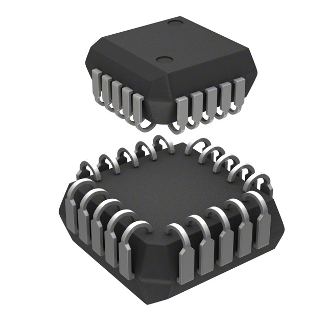
Microchip Technology AT17F080-30JU
- Part No.:
- AT17F080-30JU
- Manufacturer:
- Microchip Technology
- Category:
- Configuration PROMs for FPGAs
- Package:
- 20-LCC (J-Lead)
- Datasheet:
-
 AT17F080-30JU.pdf
- Description:
- IC FLASH CONFIG 8M 20PLCC
- Quantity:
- Payment:

- Shipping:

Inventory:112
Please send an inquiry. Send us your inquiry, and we will respond immediately.
Product details
Overview
AT17F080-30JU from Microchip Technology (formerly Atmel) is an 8-Mbit FPGA configuration PROM designed for serial master-mode loading of SRAM-based FPGAs. It delivers 8,388,608 × 1-bit storage, supports up to 33 MHz serial download clock, operates at 3.3 V ±10%, features 5.0 V-tolerant I/O pins, and is packaged in a 20-lead PLCC for industrial temperature range (−40°C to +85°C).
For engineers reviewing the AT17F080-30JU datasheet, AT17F080-30JU pinout, AT17F080-30JU application, or AT17F080-30JU equivalent, this device serves as a nonvolatile, in-system programmable configuration memory for Xilinx Virtex®, Spartan®, Altera FLEX®/APEX™, and Lucent ORCA® FPGAs - with cascading support, page-select capability, and ISP via 2-wire bus.
Technical Context
The AT17F080-30JU implements a serial flash-based architecture optimized for FPGA bitstream delivery in Master Serial mode. Its control logic synchronizes with FPGA CCLK, uses CE and RESET/OE to manage address counter reset and DATA output enable, and supports daisy-chained configurations via CEO-to-CE interconnection.
It integrates dual operational modes: SER_EN = High enables standard FPGA configuration readout with 33 MHz max clock; SER_EN = Low activates 2-wire ISP programming using internal charge-pump voltage generation. Page-select logic (PAGE_EN + PAGESEL[1:0]) partitions the 8-Mbit address space into four 2-Mbit pages for multi-bitstream reconfiguration.
Key Specifications
| Parameter | Value and Actual Design Meaning |
|---|---|
| Memory Density | 8,388,608 × 1-bit (8 Mbit), sufficient to store full configuration bitstreams for mid-to-high-end SRAM FPGAs like Xilinx XC5200 or Virtex-E. |
| Supply Voltage | 3.3 V ±10% (2.97–3.63 V), compatible with modern FPGA I/O banks and eliminates need for level-shifting circuitry. |
| Max Clock Frequency | 33 MHz during configuration readout (SER_EN = High), enabling sub-100 ms bitstream load times for typical FPGA designs. |
| I/O Voltage Tolerance | 5.0 V tolerant inputs, allowing direct interface with legacy 5 V control logic without external clamping or translation. |
| Endurance | 100,000 write cycles, supporting repeated field updates for prototyping, firmware revision, or reconfigurable system maintenance. |
| Operating Temperature | −40°C to +85°C industrial grade, validated for deployment in embedded industrial controllers and telecom infrastructure. |
| Standby Current | <1 mA at 3.3 V when CE = High and SER_EN = High, minimizing power impact during FPGA idle states. |
Pinout & Package
AT17F080-30JU is housed in a 20-lead Plastic J-Leaded Chip Carrier (PLCC) package per JEDEC MS-018 AA, with 1.27 mm pitch, body size 9.78 mm × 9.78 mm × 4.57 mm, and Sn lead finish (RoHS compliant). Pin 1 identifier is marked by a corner chamfer.
| Pin/Terminal | Circuit Role | Design Meaning |
|---|---|---|
| DATA | Bi-directional open-collector I/O | Drives FPGA DIN during configuration; tri-stated during standby or reset; supports bidirectional ISP data transfer. |
| CLK | Input | Synchronizes bitstream readout with FPGA CCLK; determines configuration speed up to 33 MHz. |
| PAGE_EN | Input | Enables 4-page partitioning of 8-Mbit memory; must be held low for flat-address-space operation. |
| PAGESEL[1:0] | Inputs | Select one of four 2-Mbit pages (00–11) when PAGE_EN = High; tied high/low for static page selection. |
| RESET/OE | Input (dual-function) | Active-low reset clears address/bit counters; active-high output enable activates DATA driver when CE is low. |
| CE | Input (active-low) | Enables configuration readout and counter increment; disables device and forces standby when high. |
| GND | Power reference | Ground return path; requires 0.2 μF decoupling capacitor between VCC and GND per datasheet recommendation. |
| CEO | Output | Chains to next device's CE; goes low after final bit is read, enabling automatic daisy-chain handoff. |
| A2 | Input (ISP mode only) | Device select during 2-wire programming; inactive during normal FPGA configuration (SER_EN = High). |
| READY | Open-collector output | Indicates power-on reset completion; driven low during POR, released (high-Z) when ready for configuration. |
| SER_EN | Input | High = FPGA configuration mode; Low = 2-wire ISP programming mode; must be tied to VCC for normal use. |
| VCC | Power supply | +3.3 V supply input; powers all internal logic, flash array, and I/O buffers; tolerance ±10%. |
Key Features
| Feature | Design Value |
|---|---|
| In-system programmability (ISP) | Enables field updates via 2-wire serial bus without removing the device; no external programming voltage required. |
| Cascadable CEO output | Allows daisy-chaining multiple AT17F080-30JU devices to support larger FPGA configurations or multi-FPGA systems. |
| Page-select configuration memory | Four independent 2-Mbit pages enable runtime switching between different FPGA configurations (e.g., functional modes or revisions). |
| 5.0 V-tolerant I/O | Permits direct connection to 5 V control signals (e.g., legacy microcontrollers or level-shifter-free FPGA mode pins). |
| Low-power standby mode | Consumes <1 mA when CE = High, reducing system-level quiescent power in always-on embedded applications. |
| Emulation of AT24C EEPROMs | Supports compatibility with existing AT24C-based programming infrastructure and software tools. |
Applications
| Industrial PLC Reconfiguration | Xilinx Virtex-Based Prototyping |
|---|---|
|
Use Scenario: Field-deployed programmable logic controllers require firmware updates to adapt to new sensor interfaces or control algorithms. IC Role / Device Role / Timing Role: AT17F080-30JU stores and delivers updated FPGA configuration bitstreams on power-up or command, acting as the primary nonvolatile configuration source. Use Value: Enables zero-downtime reconfiguration via ISP; page-select feature allows A/B firmware versions to coexist and switch without reprogramming. |
Use Scenario: Engineering teams validate hardware designs using Xilinx Virtex FPGAs on development boards before ASIC tape-out. IC Role / Device Role / Timing Role: AT17F080-30JU provides fast, reliable serial bitstream loading in Master Serial mode synchronized to FPGA CCLK. Use Value: 33 MHz max clock ensures sub-100 ms configuration time; PLCC package supports socketed prototyping and easy device replacement. |
| Altera APEX-Based Telecom Line Cards | Dual-FPGA Sensor Fusion Systems |
|
Use Scenario: Telecom line cards integrate Altera APEX FPGAs for protocol processing and require robust, field-upgradable configuration storage. IC Role / Device Role / Timing Role: AT17F080-30JU serves as the dedicated configuration PROM, interfacing directly with APEX master serial pins (DIN, CCLK, nCONFIG). Use Value: 5.0 V-tolerant I/O simplifies integration with legacy backplane control logic; industrial temp rating ensures reliability in chassis environments. |
Use Scenario: Autonomous sensor nodes combine two FPGAs-one for real-time signal processing, another for AI inference-requiring coordinated startup. IC Role / Device Role / Timing Role: AT17F080-30JU devices are cascaded (CEO→CE) to sequentially configure both FPGAs from a single bitstream chain. Use Value: Automatic CEO handoff eliminates need for external sequencing logic; reduces BOM count and PCB routing complexity. |
Equivalent & Alternatives
The following parts are listed as comparable options for similar FPGA configuration memory applications.
| Alternative Part | Technical Difference | Application Difference | Selection Advice |
|---|---|---|---|
| Xilinx XC18V08PC44C | 8-Mbit serial PROM in 44-pin TQFP; requires 3.3 V supply but lacks 5 V-tolerant I/O and page-select capability. | Designed exclusively for Xilinx FPGAs; no native support for Altera or Lucent ORCA devices. | Prefer AT17F080-30JU when multi-vendor FPGA compatibility, ISP, or page-based reconfiguration is required. |
| Microchip (Atmel) AT17F080-30CU | Same 8-Mbit density and functionality, but in 8-pad LAP (6 mm × 6 mm) instead of 20-lead PLCC; identical electrical specs and timing. | Used where board space is constrained and surface-mount assembly is preferred over through-hole or socketed PLCC. | Select AT17F080-30JU when socket-based prototyping, thermal mass requirements, or legacy PLCC footprint compatibility are priorities. |
Compared with XC18V08PC44C, AT17F080-30JU offers broader FPGA vendor support and in-system programmability; compared with AT17F080-30CU, it provides mechanical and assembly flexibility via the PLCC package while retaining identical configuration performance and feature set.
Availability
AT17F080-30JU is available at Aetrix Electronics and suitable for industrial automation, telecom infrastructure, and FPGA-based prototyping requiring stable component supply, long-lifecycle support, and RoHS-compliant packaging.
Supply support for AT17F080-30JU includes scheduled delivery planning, volume procurement assistance, BOM continuity management, traceable sourcing, and lifecycle availability coordination for OEM customers, industrial embedded developers, connected-device designers, and electronics production programs.
Manufacturer
Microchip Technology acquired Atmel in 2016 and maintains full support for legacy Atmel FPGA configuration products. The company specializes in microcontrollers, analog, FPGA, and nonvolatile memory solutions for industrial, automotive, and communications markets.
The AT17F series was developed by Atmel specifically to provide cost-effective, in-system programmable configuration memory for SRAM-based FPGAs across multiple vendors - emphasizing ease of integration, cascading scalability, and field-upgrade capability.
FAQ
What is the primary function of the AT17F080-30JU in an FPGA-based system?
The AT17F080-30JU functions as a serial configuration PROM that stores and delivers FPGA bitstreams during power-up or reconfiguration. It interfaces directly with SRAM-based FPGAs (e.g., Xilinx Virtex®, Altera APEX™) in Master Serial mode, using CLK, DATA, CE, and RESET/OE signals. Its 8-Mbit capacity supports complex FPGA designs, and its PLCC package enables socketed deployment for prototyping and field updates. AT17F080-30JU eliminates the need for external controllers during configuration.
Does the AT17F080-30JU support in-system programming (ISP), and how is it enabled?
Yes, the AT17F080-30JU supports ISP via a 2-wire serial interface. ISP is activated by driving the SER_EN pin low, which places the device into programming mode and repurposes A2 as a chip-select input. Programming occurs at 3.3 V only, with internal charge-pump circuitry generating required voltages - no external high-voltage supply is needed. Standard industry programmers (e.g., ATDH2200E, ATDH2225) and third-party tools support this mode. AT17F080-30JU retains full configuration functionality when SER_EN is high.
How does the page-select feature of the AT17F080-30JU improve system flexibility?
The AT17F080-30JU divides its 8-Mbit memory into four 2-Mbit pages using PAGE_EN and PAGESEL[1:0] inputs. When PAGE_EN is high, users can select any page to load independently - enabling runtime switching between different FPGA configurations (e.g., test vs. production, sensor A vs. sensor B). This eliminates the need to reprogram the entire device for minor updates. AT17F080-30JU maintains full backward compatibility with flat-address operation when PAGE_EN is held low.
Can the AT17F080-30JU be used in daisy-chain configurations, and what pin enables this?
Yes, the AT17F080-30JU supports daisy-chaining via its CEO (Chip Enable Output) pin. After completing its own bitstream delivery, CEO goes low and automatically enables the CE input of the next AT17F080-30JU (or compatible device) in the chain. This enables seamless cascaded configuration of multiple FPGAs or expansion beyond 8 Mbit. The CEO pin is electrically compatible with CE inputs across the AT17F family, and AT17F080-30JU's timing specifications guarantee reliable handoff under 33 MHz operation.
What are the key electrical differences between the AT17F080-30JU and the AT17F080-30CU?
The AT17F080-30JU and AT17F080-30CU share identical memory density (8 Mbit), timing (33 MHz max clock), voltage (3.3 V ±10%), I/O tolerance (5 V), and functional features (page select, ISP, cascading). Their sole difference is packaging: AT17F080-30JU uses a 20-lead PLCC for socketed or through-hole assembly, while AT17F080-30CU uses an 8-pad LAP for compact surface-mount layouts. Both are RoHS-compliant with Sn finish and rated for −40°C to +85°C. AT17F080-30JU is selected when mechanical robustness or legacy footprint compatibility is required.
AT17F080-30JU Specifications
- Product attributes
- Attribute value
- Manufacturer:
- Microchip Technology
- Series:
- -
- Package/Case:
- 20-LCC (J-Lead)
- Packaging:
- Tube
- Product Status:
- Obsolete
- Programmable:
- Not Verified
- Programmable Type:
- FLASH
- Memory Size:
- 8Mb
- Voltage - Supply:
- 2.97V ~ 3.63V
- Operating Temperature:
- -40°C ~ 85°C
- Mounting Type:
- Surface Mount
- Supplier Device Package:
- 20-PLCC (9x9)
AT17F080-30JU FAQ
1.How can I place an order for AT17F080-30JU through Aetrix?
Please submit a Request for Quotation (RFQ) for AT17F080-30JU on Aetrix. Our sales agent will provide a competitive quotation and guide you through the order confirmation once you accept the terms.
2.Are the price and stock information for AT17F080-30JU reliable?
The price and inventory of AT17F080-30JU are updated periodically and may fluctuate due to market conditions. Stock and pricing data are typically refreshed every 24 hours. Quotation validity for AT17F080-30JU is usually 5 days.
3.What payment methods are accepted for AT17F080-30JU?
We accept Wire Transfer, PayPal, Credit Card, Western Union, MoneyGram, and Escrow for AT17F080-30JU transactions.
Note: Certain payment methods may incur a processing fee.
4.How is shipping managed for AT17F080-30JU?
AT17F080-30JU orders can be shipped via leading logistics carriers, including DHL, UPS, FedEx, TNT, or Registered Mail.
Once your AT17F080-30JU order is processed, you will receive an email with the shipment details and tracking number.
Note: Tracking information may take up to 24 hours to appear. Express delivery typically takes 3–5 business days.
5.How can I obtain technical support or documentation for AT17F080-30JU?
For technical support, including AT17F080-30JU datasheets, pinout diagrams, or application guidance, please contact our engineering support team. They can provide detailed documentation and assistance for your AT17F080-30JU requirements.
6.How does Aetrix verify that AT17F080-30JU is sourced from the original manufacturer or authorized distributors?
All AT17F080-30JU products on Aetrix are procured from qualified distributors and authorized channels. Our dedicated quality assurance team conducts strict verification, including traceability checks and, if necessary, third-party testing. This ensures that AT17F080-30JU meets industry standards.
7.What is the process for return or replacement of AT17F080-30JU?
All AT17F080-30JU units undergo pre-shipment inspection (PSI). If there is an issue with AT17F080-30JU, returns or replacements are accepted under the following conditions:
1.Quantity discrepancies, incorrect items, or visible external defects (such as breakage or corrosion), acknowledged by Aetrix.
2.The issue is reported within 90 days of delivery.
3.The AT17F080-30JU part is unused and in its original packaging.
Return procedure for AT17F080-30JU:
1.Submit a request within 90 days.
2.Obtain a Return Material Authorization (RMA) from Aetrix.
AT17F080-30JU Tags

-
AT17LV512A-10PU
Microchip Technology

-
EPCQ4ASI8N
Intel
-
AT17LV256-10PU
Microchip Technology

-
AT17LV256-10NU
Microchip Technology
-
EPCQ16ASI8N
Intel
-
AT17LV010-10PU
Microchip Technology
-
EPCQ32ASI8N
Intel

-
EPCQ64ASI16N
Intel
-
EPCQ128ASI16N
Intel
-
AT17LV512A-10JU
Microchip Technology
-
AT17LV512-10JU
Microchip Technology
-
AT17LV010-10JU
Microchip Technology
Tech Hub

TTL and CMOS logic families differ in thresholds, loading, output drive, power and timing. This engineering guide compares 74HC and 74HCT, calculates noise margins and checks 3.3 V/5 V compatibility.

A practical engineering guide to 3.3V and 5V logic compatibility, input thresholds, resistor dividers, translator ICs, MOSFET level shifting, I2C pull-ups, timing limits and power-sequencing risks.

The 74HC595 uses push-pull logic outputs, while the TPIC6B595 uses 50 V open-drain DMOS sinks for higher-power loads. This guide compares timing, current limits, 3.3 V interfacing, load wiring, thermal…

The 74HC595 converts serial data into eight stable parallel outputs. This guide covers pin functions, shift and storage timing, OE and MR behavior, drive-current limits, cascading, voltage compatibilit…

A technical comparison of level-sensitive latches and edge-triggered flip-flops, covering timing windows, setup and hold limits, master–slave operation, time borrowing, race-through, HDL inference and…

A D latch stores one bit while Enable controls when data can pass. This reference covers gate-level operation, truth tables, transparency, setup and hold timing, LE versus OE, common ICs and practical …

An SR latch stores one bit through cross-coupled feedback. This engineering reference covers NOR and NAND implementations, truth tables, forbidden-state recovery, gated operation, switch debouncing, fa…

Latch circuits retain one bit through feedback. This technical reference covers SR and D latches, truth tables, transparency, timing limits, latch-versus-flip-flop behavior, applications and common log…

An engineering guide to LED driver operation, constant-current and constant-voltage outputs, linear and switching topologies, dimming, IC selection, calculations, replacement compatibility, and fault c…

Operational amplifier guide covering op amp basics, feedback, ideal vs real op amps, common configurations, buffer circuits, offset, bias current, gain-bandwidth, slew rate, rail-to-rail limits and sel…


