
 My Inquiry
 My Account


Microchip Technology AT17F32-30BJI
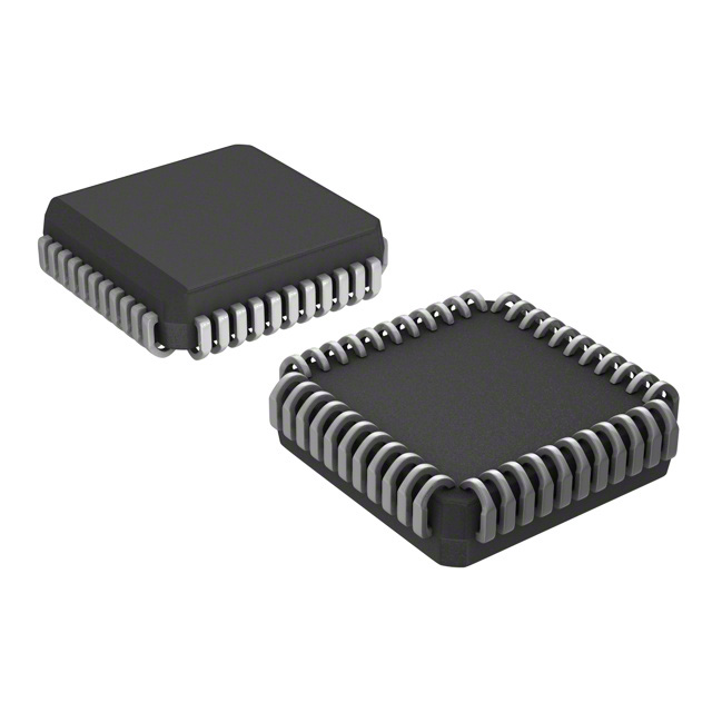
- Part No.:
- AT17F32-30BJI
- Manufacturer:
- Microchip Technology
- Category:
- Configuration PROMs for FPGAs
- Package:
- 44-LCC (J-Lead)
- Datasheet:
-
 AT17F32-30BJI.pdf
- Description:
- IC EEPROM FLASH 32MBIT 44-PLCC
- Quantity:
- Payment:

- Shipping:

Inventory:1,585
Please send an inquiry. Send us your inquiry, and we will respond immediately.
Product details
Overview
AT17F32-30BJI from Microchip Technology (formerly Atmel) is an industrial-grade, 32-Mbit serial configuration PROM designed to store and deliver FPGA bitstreams in Master Serial mode. It delivers 33 MHz serial download speed, supports 4-page memory partitioning via PAGESEL[1:0], features 5V-tolerant I/O pins, and operates from 2.97–3.63 V over –40°C to +85°C for reliable reconfiguration of Xilinx Virtex/Spartan, Lattice ORCA, and Altera FLEX/APEX FPGAs.
For engineers reviewing the AT17F32-30BJI datasheet, AT17F32-30BJI pinout, AT17F32-30BJI application, or AT17F32-30BJI equivalent, key selection criteria include industrial temperature support, PLCC-44 package compatibility with legacy FPGA carrier boards, cascading CEO/CE daisy-chain capability, ISP via 2-wire bus with SER_EN control, and page-selectable 8-Mbit partitions for multi-configuration systems.
Technical Context
The AT17F32-30BJI implements a serial flash-based configuration memory architecture with synchronous read-out driven by FPGA CCLK. Its internal address counter auto-resets on power-up or RESET/OE assertion, and CEO output enables seamless daisy-chaining by gating CE of the next device upon end-of-data detection.
It supports two distinct operational modes: FPGA configuration mode (SER_EN = High), where CLK, CE, and RESET/OE coordinate bitstream delivery; and In-System Programming mode (SER_EN = Low), where A2 and 2-wire interface enable field reprogramming without socket removal - all using only 3.3 V supply with on-chip charge pumps.
Key Specifications
| Parameter | Value and Actual Design Meaning |
|---|---|
| Memory Size | 32 Mbit (4,194,304 × 8-bit equivalent), sufficient for full configuration of mid-to-high-end SRAM FPGAs like Virtex-II or Stratix. |
| Max Clock Frequency | 33 MHz during configuration (SER_EN = High), enabling sub-100 ms bitstream load for typical 2–4 Mbit designs. |
| Operating Voltage | 2.97–3.63 V - compatible with 3.3 V FPGA I/O rails and tolerant of standard supply ripple without external regulation. |
| Temperature Range | –40°C to +85°C industrial grade - qualified for deployment in factory automation, outdoor telecom, and embedded control systems. |
| Write Endurance | 10,000 write cycles - supports field firmware updates and design iteration across product lifecycle. |
| Standby Current | ≤3 mA at 3.3 V - minimizes system-level quiescent power when FPGA is idle or held in reset. |
| Page Partitioning | 4 × 8-Mbit pages selectable via PAGESEL[1:0] + PAGE_EN - enables runtime switching between hardware configurations (e.g., sensor mode vs. comms mode). |
Pinout & Package
AT17F32-30BJI is housed in a 44-lead Plastic Leaded Chip Carrier (PLCC-44, JEDEC MS-018 AC), with lead pitch 1.27 mm, body size 17.5 mm × 17.5 mm, and J-bend leads suitable for through-hole or surface-mount reflow assembly.
| Pin | Circuit Role | Design Meaning |
|---|---|---|
| DATA (Pin 2) | Bi-directional open-collector I/O | Drives FPGA DIN during configuration; used for 2-wire programming when SER_EN = Low; requires external pull-up. |
| CLK (Pin 5) | Input | Synchronizes bitstream readout; sourced directly from FPGA CCLK - no external clock generator needed. |
| RESET/OE (Pin 19) | Input/Output control | Active-Low reset clears address counter; active-High enables DATA output - dual function eliminates need for separate OE logic. |
| CE (Pin 21) | Input | Chip Enable (active Low); controls data output and counter enable; tied Low during config, High for standby. |
| CEO (Pin 27) | Output | Chained CE signal - goes Low at final address to enable next PROM in daisy chain; critical for multi-device systems. |
| READY (Pin 29) | Open-collector status indicator | Signals power-on reset completion - drives Low during POR, released after internal initialization (~100 µs typical). |
| SER_EN (Pin 41) | Input | Selects operational mode: High = FPGA config mode; Low = 2-wire ISP mode - must be hardwired to VCC unless field programming required. |
| VCC (Pin 44) | Power | +3.3 V ±10% supply - powers all logic and internal charge pumps; decoupling with 0.2 µF capacitor to GND mandatory. |
Key Features
| Feature | Design Value |
|---|---|
| In-System Programmability | Enables field reprogramming via 2-wire interface without removing AT17F32-30BJI from PCB - reduces service downtime and NRE for FPGA design changes. |
| 4-Page Memory Partitioning | Allows storage of up to four independent FPGA configurations (e.g., calibration, test, production, fail-safe) and dynamic selection via PAGESEL[1:0] pins. |
| Daisy-Chain CEO Output | Eliminates need for external logic to cascade multiple AT17F32-30BJI devices - simplifies board layout and ensures deterministic timing across chained PROMs. |
| 5V-Tolerant I/O Pins | Permits direct interfacing with 5 V legacy FPGA development platforms or level-shifting-free integration into mixed-voltage systems. |
| Low-Power Standby Mode | Draws ≤3 mA when CE = High and SER_EN = High - supports energy-sensitive applications such as battery-backed industrial controllers. |
Applications
| Industrial PLC Reconfiguration | Multi-Mode Sensor Hub |
|---|---|
|
Use Scenario: Programmable logic controller upgrades its FPGA gateware remotely to adapt to new I/O modules or field protocols. IC Role / Device Role / Timing Role: AT17F32-30BJI serves as master serial configuration memory, delivering verified bitstreams on power-up or command-triggered reload. Use Value: Enables zero-downtime FPGA reconfiguration in harsh environments - validated for –40°C to +85°C operation and immune to voltage transients on 5V-tolerant pins. |
Use Scenario: A single sensor aggregation node switches between vibration analysis, thermal imaging, and RF spectrum capture modes. IC Role / Device Role / Timing Role: AT17F32-30BJI stores four distinct FPGA configurations; PAGESEL[1:0] selects mode-specific logic at runtime without host CPU intervention. Use Value: Reduces BOM count and PCB area versus discrete PROMs - one AT17F32-30BJI replaces four smaller memories while maintaining deterministic <33 MHz load timing. |
| Telecom Line Card Boot | Defense Radar Signal Processor |
|
Use Scenario: Carrier-grade line card boots FPGA-based packet processing logic within strict 200 ms power-on timing budget. IC Role / Device Role / Timing Role: AT17F32-30BJI provides high-speed serial bitstream delivery synchronized to FPGA CCLK, with READY pin confirming initialization readiness. Use Value: 33 MHz max clock ensures full 32-Mbit load completes in <1 s - meets ITU-T GR-1089-CORE surge immunity requirements with robust PLCC-44 mechanical stability. |
Use Scenario: Radar front-end processes real-time beamforming algorithms requiring secure, tamper-resistant FPGA configuration. IC Role / Device Role / Timing Role: AT17F32-30BJI holds encrypted bitstream; cascaded CEO/CE chaining allows redundant PROM pairs for fault-tolerant loading. Use Value: Industrial temp grade and 10,000 write cycles support mission-critical reprogramming in airborne or ground-mobile platforms with extended service life. |
Equivalent & Alternatives
The following parts are listed as comparable options for similar FPGA configuration memory applications.
| Alternative Part | Technical Difference | Application Difference | Selection Advice |
|---|---|---|---|
| Xilinx XC18V02 | 2-Mbit capacity, 3.3 V only, no page partitioning, no SER_EN-controlled ISP mode. | Limited to small FPGAs (e.g., Spartan-IIE); lacks multi-configuration flexibility and field-programmability. | Select only if bitstream size ≤2 Mbit and no runtime reconfiguration is needed. |
| Microchip (Atmel) AT17LV32-10JU | Same 32-Mbit density and PLCC-44 package, but commercial temp range (0°C to +70°C) and 10 MHz max clock (vs. 33 MHz). | Suitable for lab prototypes or non-industrial deployments; cannot meet timing or environmental specs of AT17F32-30BJI. | Choose only for cost-sensitive, non-ruggedized applications where industrial qualification is unnecessary. |
Compared with XC18V02 and AT17LV32-10JU, the AT17F32-30BJI uniquely combines industrial temperature rating, 33 MHz configuration speed, 4-page memory segmentation, and true 2-wire ISP - making it the only option among the three qualified for field-upgradable, high-reliability FPGA systems operating across extended thermal and electrical stress conditions.
Availability
AT17F32-30BJI is available at Aetrix Electronics and suitable for industrial automation, telecom infrastructure, defense electronics, and embedded FPGA development requiring stable component supply across long production lifecycles.
Supply support for AT17F32-30BJI includes scheduled delivery planning, volume procurement assistance, BOM continuity management, traceable sourcing, and lifecycle availability coordination for OEM customers, industrial embedded developers, connected-device designers, and electronics production programs.
Manufacturer
Microchip Technology acquired Atmel in 2016 and maintains full support for legacy Atmel FPGA configuration products including the AT17F series.
The AT17F32-30BJI belongs to Microchip's FPGA Configuration PROM product line, engineered specifically for reliable, high-speed, and field-reprogrammable bitstream delivery to SRAM-based FPGAs in demanding industrial and aerospace environments.
FAQ
What is the primary function of the AT17F32-30BJI in an FPGA-based system?
The AT17F32-30BJI functions as a dedicated serial configuration PROM that stores and delivers FPGA bitstreams during power-up or reconfiguration events. It interfaces directly with SRAM-based FPGAs (e.g., Xilinx Virtex, Altera Stratix) in Master Serial mode, using CLK from the FPGA to synchronize data delivery on the DATA pin. Its design eliminates the need for external microcontrollers or complex boot logic - the AT17F32-30BJI handles address counting, page selection, and daisy-chain handoff autonomously.
Does the AT17F32-30BJI support in-system programming, and how is it enabled?
Yes, the AT17F32-30BJI supports In-System Programming (ISP) via a 2-wire serial interface. This mode is activated by driving the SER_EN pin Low, which disables normal configuration operation and enables A2 and DATA as programming pins. The AT17F32-30BJI uses internal charge pumps to generate programming voltages - no external high-voltage supply is required. Programming can be performed using Atmel's ATDH2200E kit or compatible third-party programmers, and the AT17F32-30BJI retains full functionality after field updates.
How does the page partitioning feature work on the AT17F32-30BJI?
The AT17F32-30BJI supports 4-page memory partitioning when PAGE_EN is set High. The two PAGESEL[1:0] inputs select one of four 8-Mbit address ranges (000000–07FFFFh, 080000–0FFFFFh, etc.), allowing independent storage and runtime selection of FPGA configurations. When PAGE_EN is Low, the full 32-Mbit space is contiguous (000000–1FFFFFh). This feature enables single-hardware platforms to host multiple functional modes - for example, a test configuration, production firmware, calibration data, and fail-safe recovery logic - all accessible without changing hardware.
Can the AT17F32-30BJI be used in a daisy-chain configuration with other PROMs?
Yes, the AT17F32-30BJI supports hardware daisy-chaining via its CEO (Chip Enable Output) pin. When the internal address counter reaches the end of its selected memory region, CEO asserts Low, enabling the CE input of the next AT17F32-30BJI (or compatible PROM) in the chain. This allows seamless expansion beyond 32 Mbit - for example, cascading two devices yields 64 Mbit total capacity. The CEO signal also ensures deterministic handoff timing, eliminating race conditions common in software-managed multi-PROM systems.
What are the key electrical differences between the AT17F32-30BJI and the commercial-grade AT17F32-30BJC?
The AT17F32-30BJI is rated for industrial temperature operation (–40°C to +85°C) and guarantees 33 MHz maximum clock frequency under those conditions, whereas the AT17F32-30BJC is specified only for 0°C to +70°C and shares the same 33 MHz rating only in commercial conditions. Both use identical PLCC-44 packaging and pinout, but the AT17F32-30BJI undergoes extended burn-in and screening to ensure reliability in thermally stressed environments - making it the required choice for factory-floor controllers, outdoor base stations, and vehicle-mounted systems where ambient temperature exceeds 70°C.
AT17F32-30BJI Specifications
- Product attributes
- Attribute value
- Manufacturer:
- Microchip Technology
- Series:
- -
- Package/Case:
- 44-LCC (J-Lead)
- Packaging:
- Tube
- Product Status:
- Obsolete
- Programmable:
- Not Verified
- Programmable Type:
- FLASH
- Memory Size:
- 32Mb
- Voltage - Supply:
- 2.97V ~ 3.63V
- Operating Temperature:
- -40°C ~ 85°C
- Mounting Type:
- Surface Mount
- Supplier Device Package:
- 44-PLCC (16.6x16.6)
AT17F32-30BJI FAQ
1.How can I place an order for AT17F32-30BJI through Aetrix?
Please submit a Request for Quotation (RFQ) for AT17F32-30BJI on Aetrix. Our sales agent will provide a competitive quotation and guide you through the order confirmation once you accept the terms.
2.Are the price and stock information for AT17F32-30BJI reliable?
The price and inventory of AT17F32-30BJI are updated periodically and may fluctuate due to market conditions. Stock and pricing data are typically refreshed every 24 hours. Quotation validity for AT17F32-30BJI is usually 5 days.
3.What payment methods are accepted for AT17F32-30BJI?
We accept Wire Transfer, PayPal, Credit Card, Western Union, MoneyGram, and Escrow for AT17F32-30BJI transactions.
Note: Certain payment methods may incur a processing fee.
4.How is shipping managed for AT17F32-30BJI?
AT17F32-30BJI orders can be shipped via leading logistics carriers, including DHL, UPS, FedEx, TNT, or Registered Mail.
Once your AT17F32-30BJI order is processed, you will receive an email with the shipment details and tracking number.
Note: Tracking information may take up to 24 hours to appear. Express delivery typically takes 3–5 business days.
5.How can I obtain technical support or documentation for AT17F32-30BJI?
For technical support, including AT17F32-30BJI datasheets, pinout diagrams, or application guidance, please contact our engineering support team. They can provide detailed documentation and assistance for your AT17F32-30BJI requirements.
6.How does Aetrix verify that AT17F32-30BJI is sourced from the original manufacturer or authorized distributors?
All AT17F32-30BJI products on Aetrix are procured from qualified distributors and authorized channels. Our dedicated quality assurance team conducts strict verification, including traceability checks and, if necessary, third-party testing. This ensures that AT17F32-30BJI meets industry standards.
7.What is the process for return or replacement of AT17F32-30BJI?
All AT17F32-30BJI units undergo pre-shipment inspection (PSI). If there is an issue with AT17F32-30BJI, returns or replacements are accepted under the following conditions:
1.Quantity discrepancies, incorrect items, or visible external defects (such as breakage or corrosion), acknowledged by Aetrix.
2.The issue is reported within 90 days of delivery.
3.The AT17F32-30BJI part is unused and in its original packaging.
Return procedure for AT17F32-30BJI:
1.Submit a request within 90 days.
2.Obtain a Return Material Authorization (RMA) from Aetrix.
AT17F32-30BJI Tags

-
AT17LV512A-10PU
Microchip Technology

-
EPCQ4ASI8N
Intel
-
AT17LV256-10PU
Microchip Technology

-
AT17LV256-10NU
Microchip Technology
-
EPCQ16ASI8N
Intel
-
AT17LV010-10PU
Microchip Technology
-
EPCQ32ASI8N
Intel

-
EPCQ64ASI16N
Intel
-
EPCQ128ASI16N
Intel
-
AT17LV512A-10JU
Microchip Technology
-
AT17LV512-10JU
Microchip Technology
-
AT17LV010-10JU
Microchip Technology
Tech Hub

TTL and CMOS logic families differ in thresholds, loading, output drive, power and timing. This engineering guide compares 74HC and 74HCT, calculates noise margins and checks 3.3 V/5 V compatibility.

A practical engineering guide to 3.3V and 5V logic compatibility, input thresholds, resistor dividers, translator ICs, MOSFET level shifting, I2C pull-ups, timing limits and power-sequencing risks.

The 74HC595 uses push-pull logic outputs, while the TPIC6B595 uses 50 V open-drain DMOS sinks for higher-power loads. This guide compares timing, current limits, 3.3 V interfacing, load wiring, thermal…

The 74HC595 converts serial data into eight stable parallel outputs. This guide covers pin functions, shift and storage timing, OE and MR behavior, drive-current limits, cascading, voltage compatibilit…

A technical comparison of level-sensitive latches and edge-triggered flip-flops, covering timing windows, setup and hold limits, master–slave operation, time borrowing, race-through, HDL inference and…

A D latch stores one bit while Enable controls when data can pass. This reference covers gate-level operation, truth tables, transparency, setup and hold timing, LE versus OE, common ICs and practical …

An SR latch stores one bit through cross-coupled feedback. This engineering reference covers NOR and NAND implementations, truth tables, forbidden-state recovery, gated operation, switch debouncing, fa…

Latch circuits retain one bit through feedback. This technical reference covers SR and D latches, truth tables, transparency, timing limits, latch-versus-flip-flop behavior, applications and common log…

An engineering guide to LED driver operation, constant-current and constant-voltage outputs, linear and switching topologies, dimming, IC selection, calculations, replacement compatibility, and fault c…

Operational amplifier guide covering op amp basics, feedback, ideal vs real op amps, common configurations, buffer circuits, offset, bias current, gain-bandwidth, slew rate, rail-to-rail limits and sel…


