
 My Inquiry
 My Account


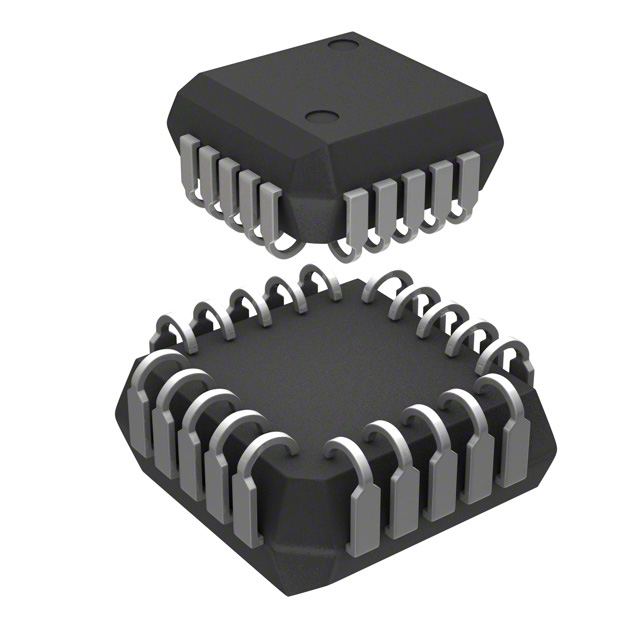
Microchip Technology AT17LV002A-10JU
- Part No.:
- AT17LV002A-10JU
- Manufacturer:
- Microchip Technology
- Category:
- Configuration PROMs for FPGAs
- Package:
- 20-LCC (J-Lead)
- Datasheet:
-
 AT17LV002A-10JU.pdf
- Description:
- IC SRL CONFIG EEPROM 2M 20-PLCC
- Quantity:
- Payment:

- Shipping:

Inventory:4,516
Please send an inquiry. Send us your inquiry, and we will respond immediately.
Product details
Overview
AT17LV002A-10JU from Microchip Technology (formerly Atmel) is a 2-Mbit serial EEPROM FPGA configuration memory designed to store and load bitstreams into SRAM-based FPGAs including Altera FLEX/APEX, Xilinx Spartan/Virtex, and ORCA devices. It supports dual-voltage operation (3.3V ±10% or 5.0V ±10%), features in-system programmability via 2-wire interface, and delivers 90-year data retention at 85°C. Its primary role is master-serial mode bootloading in industrial embedded systems.
For engineers reviewing the AT17LV002A-10JU datasheet, AT17LV002A-10JU pinout, AT17LV002A-10JU application, or AT17LV002A-10JU equivalent, key selection criteria include cascading capability via nCASC, programmable reset polarity, WP1-enabled partial write protection, low-power standby current (≤150 µA @ 3.3V), and PLCC-20 package compatibility with legacy FPGA design flows.
Technical Context
The AT17LV002A-10JU operates as a dedicated serial configuration memory in master-serial mode, interfacing directly with FPGA control pins (DCLK, nCS, RESET/OE) without external controller intervention. Its internal address counter advances on DCLK rising edges only when nCS is low and RESET/OE is high, enabling deterministic bitstream delivery.
Cascading is supported through the nCASC output, which asserts low upon completion of its 2,097,152-bit sequence to enable the next device in chain; this feature is confirmed for AT17LV002A and absent in NRND variants. SER_EN must be tied high during FPGA loading and pulled low only for ISP programming.
Key Specifications
| Parameter | Value and Actual Design Meaning |
|---|---|
| Memory Density | 2,097,152 × 1-bit (2-Mbit); sufficient to configure mid-range FPGAs like Altera EPC2 or Xilinx XC4000XL families. |
| Supply Voltage | 3.0–5.5 V; enables drop-in use in both 3.3V and 5V legacy industrial systems without level-shifting. |
| Standby Current | ≤150 µA @ 3.3V; minimizes system power budget during FPGA configuration idle states. |
| Data Retention | 90 years at 85°C; validated for long-life industrial deployments requiring unattended operation. |
| Write Endurance | 100,000 cycles; supports field firmware updates and reconfiguration in maintenance workflows. |
| Max Clock Frequency | 10 MHz @ 3.3V; ensures reliable timing margin for FPGA DCLK-driven configuration across temperature range. |
| Operating Temp | −40°C to +85°C; qualified for extended industrial environments without derating. |
Pinout & Package
AT17LV002A-10JU is packaged in a 20-lead Plastic Leaded Chip Carrier (PLCC-20), RoHS-compliant, with 1.27 mm pitch and JEDEC MS-018 AA compliance. Thermal resistance θJA = 90°C/W enables passive cooling in dense PCB layouts.
| Pin/Terminal | Circuit Role | Design Meaning |
|---|---|---|
| DATA | Three-state bidirectional I/O | Drives FPGA DIN during configuration; open-collector for wired-OR daisy-chain support. |
| DCLK | Input/Output clock | Rising edge increments address counter; driven low by device when reset or cascade complete. |
| WP1 | Input (write protect) | Enables block-level write protection; internal pull-down defaults to unprotected state. |
| RESET/OE | Input (dual-function) | Programmable polarity: active-low reset or active-high output enable; controls DATA tristate and counter reset. |
| nCS | Input (chip select) | Active-low enable for counter and DATA; determines master/slave role in cascaded chains. |
| nCASC | Output (cascade select) | Active-low signal indicating end-of-data; connects to nCS of next device in daisy-chain. |
| A2 | Input (device select) | Used during ISP programming to select device; internal pull-down ensures default disable. |
| READY | Output (power-on indicator) | Open-collector low during power-up reset; released after VCC stabilization (requires 4.7kΩ pull-up). |
| SER_EN | Input (serial enable) | High = FPGA loading mode; Low = 2-wire ISP programming mode; tie to VCC for normal operation. |
| VCC / GND | Power / reference | Supports 3.3V or 5V supply; 0.2 µF decoupling capacitor recommended between VCC and GND. |
Key Features
| Feature | Design Value |
|---|---|
| In-system programmability | 2-wire serial interface (SER_EN-controlled) enables field reprogramming without socket removal. |
| Cascadable architecture | nCASC output allows daisy-chaining multiple AT17LV002A-10JU units to support >2-Mbit FPGA configurations. |
| Programmable reset polarity | User-configurable RESET/OE logic polarity via EEPROM bytes-critical for Altera vs. Xilinx FPGA compatibility. |
| Partial write protection | WP1 pin enables hardware-level protection of lower memory blocks during partial reconfiguration sequences. |
| Low-power standby | Consumes ≤150 µA @ 3.3V when nCS is high-reduces quiescent power in always-on industrial controllers. |
Applications
| Industrial PLC Configuration | FPGA-Based Motor Drive Bootloader |
|---|---|
Use Scenario: Reconfiguring Altera APEX FPGAs in programmable logic controllers after firmware updates or safety-critical parameter changes. IC Role / Device Role / Timing Role: Master-serial configuration memory delivering bitstream on power-up or command-triggered reload; synchronized to FPGA DCLK. Use Value: Eliminates need for external microcontroller bootloading logic; 90-year data retention ensures integrity over multi-decade PLC service life. | Use Scenario: Storing motor control algorithms and safety logic in Xilinx Spartan FPGAs used in servo drive modules. IC Role / Device Role / Timing Role: Dedicated configuration EEPROM providing deterministic startup timing and fail-safe initialization sequence. Use Value: Dual-voltage support (3.3V/5V) simplifies integration into mixed-voltage drive power stages; cascading enables expansion for multi-axis coordination logic. |
| Test Equipment FPGA Reconfiguration | Avionics Ground Support Interface |
Use Scenario: Enabling rapid FPGA reconfiguration between test modes (e.g., digital pattern generation vs. protocol analysis) in automated test equipment. IC Role / Device Role / Timing Role: Serial configuration memory supporting in-system programming via host MCU's GPIO-controlled 2-wire bus. Use Value: WP1 pin prevents accidental overwrite of golden configuration images during field service; 100,000 write cycles accommodate frequent lab calibration updates. | Use Scenario: Loading mission-specific FPGA configurations in ground-based avionics validation rigs operating in controlled industrial environments. IC Role / Device Role / Timing Role: Industrial-grade configuration memory ensuring reliable bitstream delivery under thermal cycling and vibration stress. Use Value: −40°C to +85°C rating and green (Pb/Halide-free) packaging meet DO-160 environmental and RoHS compliance requirements for ground support hardware. |
Equivalent & Alternatives
The following parts are listed as comparable options for similar FPGA configuration memory applications.
| Alternative Part | Technical Difference | Application Difference | Selection Advice |
|---|---|---|---|
| AT17LV010A-10JU | 1-Mbit density (half capacity); identical pinout, voltage, timing, and feature set. | Targeted at smaller FPGAs (e.g., Xilinx XC3000, Altera EPC1); insufficient for Virtex or large APEX devices. | Select when configuration image size is <1 Mbit and cost optimization is prioritized over future scalability. |
| Xilinx XC18V02 | 2-Mbit density, 3.3V-only operation, JTAG-compatible programming interface, different pinout (20-pin SOIC). | Designed specifically for Xilinx FPGA ecosystems; lacks nCASC and WP1; requires JTAG programmer instead of 2-wire ISP. | Choose only for Xilinx-only designs where JTAG infrastructure exists and cascading is unnecessary. |
Compared with AT17LV010A-10JU, the AT17LV002A-10JU doubles configuration capacity while maintaining full pin and functional compatibility; versus XC18V02, it offers broader FPGA vendor support, cascading, and simpler 2-wire ISP-but requires PLCC-20 footprint and dual-voltage design allowance.
Availability
AT17LV002A-10JU is available at Aetrix Electronics and suitable for industrial PLCs, FPGA-based motor drives, automated test equipment, and avionics ground support systems requiring stable component supply across extended product lifecycles.
Supply support for AT17LV002A-10JU includes scheduled delivery planning, volume procurement assistance, BOM continuity management, traceable sourcing, and lifecycle availability coordination for OEM customers, industrial embedded developers, connected-device designers, and electronics production programs.
Manufacturer
Microchip Technology acquired Atmel in 2016 and maintains legacy FPGA configuration memory product lines with full documentation and long-term supply commitment.
The AT17LVxxxA family was engineered specifically for reliable, low-risk FPGA bitstream storage in industrial and commercial systems-emphasizing ease of integration, cascading scalability, and robustness across voltage and temperature extremes.
FAQ
What is the maximum clock frequency supported by AT17LV002A-10JU during FPGA configuration?
The AT17LV002A-10JU supports a maximum input clock frequency of 10 MHz when operating at 3.3V ±10%, and 15 MHz at 5.0V ±10%. These values are specified in Table 10-6 of the datasheet and ensure setup/hold timing margins for reliable bitstream transfer to SRAM-based FPGAs. Exceeding these frequencies may cause configuration errors or data corruption in the AT17LV002A-10JU.
Does AT17LV002A-10JU support JTAG programming?
No, the AT17LV002A-10JU does not support JTAG programming. It uses a dedicated 2-wire serial interface activated by pulling SER_EN low. This is explicitly stated in Note 4 of Section 11.2 of the datasheet. JTAG-capable alternatives like Xilinx XC18V02 require different programming infrastructure and are not functionally interchangeable with AT17LV002A-10JU.
Can AT17LV002A-10JU be used in a daisy-chain configuration with other AT17LVxxxA devices?
Yes, AT17LV002A-10JU supports cascading via its nCASC output pin, which goes low upon completion of its 2-Mbit sequence to enable the next device in chain. This feature is confirmed in Tables 1-1 and 1-2 and Sections 6 and 10-5 of the datasheet. It is compatible with other AT17LV512A/010A/002A devices but not with NRND variants (AT17LV65A/128A/256A) which lack nCASC.
What is the purpose of the WP1 pin on AT17LV002A-10JU?
The WP1 pin on AT17LV002A-10JU provides hardware-level write protection for designated memory blocks during ISP programming. When asserted high, it prevents writes to the lowest memory segment; it is disabled by default due to an internal pull-down resistor. Unlike the WP pin on smaller variants, WP1 is present only on AT17LV512A/010A/002A and enables selective reconfiguration without risking corruption of critical boot code stored in lower addresses.
Is AT17LV002A-10JU compatible with both 3.3V and 5V FPGA systems?
Yes, AT17LV002A-10JU is fully compatible with both 3.3V and 5V systems, supporting supply voltages from 3.0V to 5.5V. Its I/O thresholds (VIH ≥2.0V, VIL ≤0.8V) and output drive strength (VOH ≥2.4V @ 3.3V, ≥3.6V @ 5.0V) ensure interoperability with mixed-voltage FPGA interfaces. This dual-voltage capability is highlighted in the Features section and Table 10-1 of the AT17LV002A-10JU datasheet.
AT17LV002A-10JU Specifications
- Product attributes
- Attribute value
- Manufacturer:
- Microchip Technology
- Series:
- -
- Package/Case:
- 20-LCC (J-Lead)
- Packaging:
- Tube
- Product Status:
- Active
- Programmable:
- Not Verified
- Programmable Type:
- Serial EEPROM
- Memory Size:
- 2Mb
- Voltage - Supply:
- 3V ~ 3.6V, 4.5V ~ 5.5V
- Operating Temperature:
- -40°C ~ 85°C
- Mounting Type:
- Surface Mount
- Supplier Device Package:
- 20-PLCC (9x9)
AT17LV002A-10JU FAQ
1.How can I place an order for AT17LV002A-10JU through Aetrix?
Please submit a Request for Quotation (RFQ) for AT17LV002A-10JU on Aetrix. Our sales agent will provide a competitive quotation and guide you through the order confirmation once you accept the terms.
2.Are the price and stock information for AT17LV002A-10JU reliable?
The price and inventory of AT17LV002A-10JU are updated periodically and may fluctuate due to market conditions. Stock and pricing data are typically refreshed every 24 hours. Quotation validity for AT17LV002A-10JU is usually 5 days.
3.What payment methods are accepted for AT17LV002A-10JU?
We accept Wire Transfer, PayPal, Credit Card, Western Union, MoneyGram, and Escrow for AT17LV002A-10JU transactions.
Note: Certain payment methods may incur a processing fee.
4.How is shipping managed for AT17LV002A-10JU?
AT17LV002A-10JU orders can be shipped via leading logistics carriers, including DHL, UPS, FedEx, TNT, or Registered Mail.
Once your AT17LV002A-10JU order is processed, you will receive an email with the shipment details and tracking number.
Note: Tracking information may take up to 24 hours to appear. Express delivery typically takes 3–5 business days.
5.How can I obtain technical support or documentation for AT17LV002A-10JU?
For technical support, including AT17LV002A-10JU datasheets, pinout diagrams, or application guidance, please contact our engineering support team. They can provide detailed documentation and assistance for your AT17LV002A-10JU requirements.
6.How does Aetrix verify that AT17LV002A-10JU is sourced from the original manufacturer or authorized distributors?
All AT17LV002A-10JU products on Aetrix are procured from qualified distributors and authorized channels. Our dedicated quality assurance team conducts strict verification, including traceability checks and, if necessary, third-party testing. This ensures that AT17LV002A-10JU meets industry standards.
7.What is the process for return or replacement of AT17LV002A-10JU?
All AT17LV002A-10JU units undergo pre-shipment inspection (PSI). If there is an issue with AT17LV002A-10JU, returns or replacements are accepted under the following conditions:
1.Quantity discrepancies, incorrect items, or visible external defects (such as breakage or corrosion), acknowledged by Aetrix.
2.The issue is reported within 90 days of delivery.
3.The AT17LV002A-10JU part is unused and in its original packaging.
Return procedure for AT17LV002A-10JU:
1.Submit a request within 90 days.
2.Obtain a Return Material Authorization (RMA) from Aetrix.
AT17LV002A-10JU Tags

-
AT17LV512A-10PU
Microchip Technology

-
EPCQ4ASI8N
Intel
-
AT17LV256-10PU
Microchip Technology

-
AT17LV256-10NU
Microchip Technology
-
EPCQ16ASI8N
Intel
-
AT17LV010-10PU
Microchip Technology
-
EPCQ32ASI8N
Intel

-
EPCQ64ASI16N
Intel
-
EPCQ128ASI16N
Intel
-
AT17LV512A-10JU
Microchip Technology
-
AT17LV512-10JU
Microchip Technology
-
AT17LV010-10JU
Microchip Technology
Tech Hub

A practical engineering and sourcing framework covering lifecycle verification, lifetime-buy calculations, replacement qualification, supplier checks and counterfeit-risk controls.

TTL and CMOS logic families differ in thresholds, loading, output drive, power and timing. This engineering guide compares 74HC and 74HCT, calculates noise margins and checks 3.3 V/5 V compatibility.

A practical engineering guide to 3.3V and 5V logic compatibility, input thresholds, resistor dividers, translator ICs, MOSFET level shifting, I2C pull-ups, timing limits and power-sequencing risks.

The 74HC595 uses push-pull logic outputs, while the TPIC6B595 uses 50 V open-drain DMOS sinks for higher-power loads. This guide compares timing, current limits, 3.3 V interfacing, load wiring, thermal…

The 74HC595 converts serial data into eight stable parallel outputs. This guide covers pin functions, shift and storage timing, OE and MR behavior, drive-current limits, cascading, voltage compatibilit…

A technical comparison of level-sensitive latches and edge-triggered flip-flops, covering timing windows, setup and hold limits, master–slave operation, time borrowing, race-through, HDL inference and…

A D latch stores one bit while Enable controls when data can pass. This reference covers gate-level operation, truth tables, transparency, setup and hold timing, LE versus OE, common ICs and practical …

An SR latch stores one bit through cross-coupled feedback. This engineering reference covers NOR and NAND implementations, truth tables, forbidden-state recovery, gated operation, switch debouncing, fa…

Latch circuits retain one bit through feedback. This technical reference covers SR and D latches, truth tables, transparency, timing limits, latch-versus-flip-flop behavior, applications and common log…

An engineering guide to LED driver operation, constant-current and constant-voltage outputs, linear and switching topologies, dimming, IC selection, calculations, replacement compatibility, and fault c…


