
 My Inquiry
 My Account


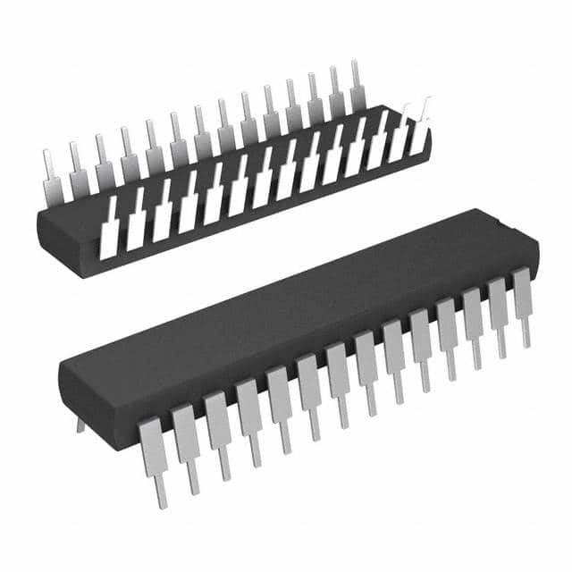
Microchip Technology AT28C64-12PI
- Part No.:
- AT28C64-12PI
- Manufacturer:
- Microchip Technology
- Category:
- Memory
- Package:
- 28-DIP (0.600", 15.24mm)
- Datasheet:
-
 AT28C64-12PI.pdf
- Description:
- IC EEPROM 64KBIT PARALLEL 28DIP
- Quantity:
- Payment:

- Shipping:

Inventory:2,630
Please send an inquiry. Send us your inquiry, and we will respond immediately.
Product details
Overview
AT28C64-12PI from Atmel is a 64 Kbit (8K × 8) parallel EEPROM with 120 ns read access time, 1 ms byte write cycle, and CMOS/TTL-compatible I/O. It operates at 5V ±10%, supports industrial temperature range (–40°C to +85°C), and features READY/BUSY output and DATA polling for write completion detection - used in firmware storage and configuration retention for microcontroller-based industrial controllers.
For engineers reviewing the AT28C64-12PI datasheet, AT28C64-12PI pinout, AT28C64-12PI application, or AT28C64-12PI equivalent, this page delivers verified electrical parameters, JEDEC-standard byte-wide pin mapping, self-timed write architecture details, and real-world use cases in embedded systems requiring nonvolatile, byte-erasable memory with direct MPU interface.
Technical Context
The AT28C64-12PI implements a self-timed byte write cycle using internal address/data latches and a control timer, eliminating external timing circuitry. It supports two write detection methods: open-drain RDY/BUSY output (pin 1) and DATA polling on I/O7, enabling flexible integration with 8-bit microprocessor buses.
Its dual-line chip enable (CE) and output enable (OE) logic prevents bus contention during read operations, while VCC sense (3.8 V threshold), power-on delay (5 ms), and signal-level write inhibit (OE high/CE high/WE high) provide robust inadvertent-write protection. The device includes 32 bytes of dedicated identification EEPROM accessible via A9 = 12 V.
Key Specifications
| Parameter | Value and Actual Design Meaning |
|---|---|
| Memory Size | 64 Kbit (8,192 × 8 bits) - provides sufficient space for boot code, calibration tables, or device configuration data in resource-constrained embedded systems. |
| Read Access Time | 120 ns - enables direct replacement of SRAM in legacy 8-bit MPU designs without wait-state insertion. |
| Byte Write Time | 1 ms (standard version) - defines minimum interval between successive byte writes; critical for firmware update sequencing and logging latency budgets. |
| Supply Voltage | 5 V ±10% - ensures compatibility with standard TTL/CMOS logic rails and eliminates need for auxiliary voltage regulation. |
| Operating Temperature | –40°C to +85°C - qualified for industrial environments including motor drives, PLC modules, and factory automation equipment. |
| Standby Current | 100 µA (CMOS mode) - reduces system-level power consumption during idle states in battery-backed or energy-sensitive applications. |
| Endurance | 10,000 write/erase cycles - supports long-term field deployment where infrequent but reliable parameter updates are required. |
| Data Retention | 10 years - guarantees persistent storage integrity across product lifecycle without refresh mechanisms. |
Pinout & Package
AT28C64-12PI is packaged in a 28-lead plastic DIP (PDIP, package code P6), compliant with JEDEC MS-011 AB standard. Pin 1 is RDY/BUSY (open-drain); pins 1 and 17 of PLCC variants are NC, but PDIP uses all 28 pins as defined.
| Pin/Terminal | Circuit Role | Design Meaning |
|---|---|---|
| A0–A12 | Address Inputs | 13-bit address bus supporting full 8K-word addressing; compatible with Z80, 8051, and 68K family MPU address lines. |
| I/O0–I/O7 | Bidirectional Data Bus | 8-bit parallel data path; tristated when CE or OE is high, enabling shared bus operation without external buffers. |
| CE | Chip Enable | Active-low global select; must be low for any read/write access - used for memory-mapped decoding in MPU address space. |
| OE | Output Enable | Active-low output gate; allows CE-controlled chip selection while enabling/disabling outputs independently - prevents bus contention. |
| WE | Write Enable | Active-low write strobe; falling edge latches address, rising edge latches data - synchronizes with MPU write timing. |
| RDY/BUSY | Status Output | Open-drain signal pulled low during write; released upon completion - supports wired-OR multi-device busy monitoring. |
| VCC | Power Supply | +5 V supply pin; internally monitored for write inhibition below 3.8 V to prevent partial writes during brown-out. |
| GND | Ground Reference | Signal and power ground reference for all inputs, outputs, and internal logic - requires low-impedance PCB connection. |
Key Features
| Feature | Design Value |
|---|---|
| Self-timed byte write | Eliminates external timing components and MPU wait-state management - simplifies design and improves reliability over externally timed EEPROMs. |
| DATA polling on I/O7 | Enables software-driven write completion detection without hardware interrupt or dedicated status line - ideal for systems with limited GPIO. |
| JEDEC byte-wide pinout | Ensures drop-in compatibility with industry-standard 28-pin parallel memory sockets and existing PCB layouts for SRAM/ROM replacements. |
| VCC sense & power-on delay | Prevents corruption during power ramp-up or brown-out by blocking writes until stable 5 V is confirmed and 5 ms internal delay expires. |
| 32-byte ID memory | Provides user-accessible nonvolatile storage for serial numbers, calibration offsets, or manufacturing traceability - accessed via A9 = 12 V and addresses 1FE0H–1FFFH. |
Applications
| Industrial PLC Configuration Storage | Medical Device Calibration Data Retention |
|---|---|
Use Scenario: Storing I/O mapping, PID tuning parameters, and alarm thresholds in programmable logic controllers deployed in factory environments. IC Role / Device Role / Timing Role: Nonvolatile configuration memory interfaced directly to an 8-bit microcontroller bus; accessed during power-up initialization and runtime parameter updates. Use Value: Ensures deterministic startup behavior and field-upgradable settings without requiring external programming hardware or battery backup. |
Use Scenario: Retaining sensor calibration coefficients and usage logs in portable diagnostic instruments operating under strict regulatory traceability requirements. IC Role / Device Role / Timing Role: Byte-erasable, long-retention memory mapped into MCU address space; written only during calibration procedures and read on every power cycle. Use Value: Meets IEC 62304 data integrity requirements with 10-year retention and 10,000-cycle endurance - eliminating need for FRAM or external NVSRAM. |
| Legacy Industrial HMI Firmware Storage | Automotive ECU Bootloader Parameter Table |
Use Scenario: Hosting boot firmware and UI assets in human-machine interface terminals with aging 8051-based controllers and no flash upgrade capability. IC Role / Device Role / Timing Role: Parallel EEPROM acting as primary code store; read at reset vector with 120 ns access matching MPU bus timing. Use Value: Enables firmware patching in the field using standard ISP tools and avoids costly PCB redesign to support modern serial flash interfaces. |
Use Scenario: Holding vehicle-specific configuration tables (e.g., fuel map offsets, CAN node IDs) in engine control units where reprogramming occurs infrequently during service intervals. IC Role / Device Role / Timing Role: Electrically erasable nonvolatile memory accessed via automotive-grade 8-bit MCU; written under controlled voltage conditions with built-in VCC sensing. Use Value: Guarantees safe, corruption-free updates even during marginal battery conditions - leveraging 3.8 V write-inhibit threshold and automatic clear-before-write. |
Equivalent & Alternatives
The following parts are listed as comparable options for similar parallel EEPROM applications.
| Alternative Part | Technical Difference | Application Difference | Selection Advice |
|---|---|---|---|
| AT28C64B-12PI | Enhanced revision with improved data retention (20 years) and tighter AC specs; same pinout, voltage, and timing. | Preferred for new designs requiring extended lifecycle support and higher reliability margin; backward compatible with AT28C64-12PI PCBs. | Select when long-term obsolescence mitigation and certified 20-year data retention are required - no layout or firmware changes needed. |
| MX28F640JTI-12 | Intel-compatible 64 Kbit JEDEC EEPROM; 120 ns access, but requires external WE timing control and lacks RDY/BUSY output. | Suitable for systems already designed around Intel 28Fxx timing models; not drop-in due to missing self-timed write and status signaling. | Choose only if migrating from legacy Intel 28F640 designs - expect firmware modifications for write polling and layout review for timing margin. |
Compared with AT28C64-12PI, AT28C64B-12PI offers extended data retention and enhanced process stability without altering system timing or layout, while MX28F640JTI-12 demands external timing control and removes hardware-based write completion signaling - increasing firmware complexity and reducing robustness in brown-out scenarios.
Availability
AT28C64-12PI is available at Aetrix Electronics and suitable for industrial control systems, medical instrumentation, and legacy HMI platforms requiring stable component supply, long-lifecycle support, and JEDEC-standard parallel EEPROM compatibility.
Supply support for AT28C64-12PI includes scheduled delivery planning, volume procurement assistance, BOM continuity management, traceable sourcing, and lifecycle availability coordination for OEM customers, industrial embedded developers, connected-device designers, and electronics production programs.
Manufacturer
Atmel Corporation (now part of Microchip Technology) is a fabless semiconductor company specializing in microcontrollers, nonvolatile memory, and secure authentication ICs for industrial, automotive, and consumer applications.
The AT28C64 series was designed as a pin-compatible, direct-replacement EEPROM for SRAM and mask ROM in 8-bit MPU systems - emphasizing ease of integration, robust write protection, and industrial temperature operation without external timing components.
FAQ
What is the maximum operating temperature range for AT28C64-12PI?
The AT28C64-12PI is rated for industrial temperature operation from –40°C to +85°C. This specification is validated per the manufacturer's DC and AC operating range table and applies to all package variants including the PDIP (P6) version. The device maintains full functionality-including 120 ns read access, 1 ms write timing, and 100 µA standby current-across this entire range. AT28C64-12PI is commonly deployed in motor control cabinets and outdoor automation enclosures where ambient thermal stress is present.
Does AT28C64-12PI support both RDY/BUSY and DATA polling for write completion detection?
Yes, AT28C64-12PI supports both RDY/BUSY (via open-drain pin 1) and DATA polling (on I/O7) to detect write completion. During a byte write, RDY/BUSY is actively pulled low and released upon finish; simultaneously, reading the target address returns complemented data on I/O7 until completion, then true data. This dual-method flexibility allows designers to choose hardware interrupt-driven or software-polling approaches depending on system resource constraints. Both methods are fully functional in the AT28C64-12PI PDIP variant.
Is AT28C64-12PI pin-compatible with standard 28-pin SRAM or ROM devices?
Yes, AT28C64-12PI uses a JEDEC-approved byte-wide pinout identical to industry-standard 28-pin parallel memories such as the 6264 SRAM and 2764 EPROM. Address lines A0–A12, data I/O0–I/O7, CE, OE, WE, VCC, and GND align exactly - enabling direct socket replacement in existing designs. No PCB modification is required, though firmware must accommodate write timing differences and status monitoring. This compatibility is explicitly confirmed in the "JEDEC Approved Byte-wide Pinout" feature listing and Pin Configurations section of the datasheet.
What write protection mechanisms does AT28C64-12PI implement to prevent accidental writes?
AT28C64-12PI implements three independent write protection mechanisms: (1) VCC sense - write is inhibited if VCC drops below ~3.8 V; (2) power-on delay - a 5 ms internal timer blocks writes after power-up until supply stabilizes; and (3) signal-level inhibit - holding OE high, CE high, or WE high disables all write operations. These features operate concurrently and are active across the full industrial temperature range. They ensure AT28C64-12PI remains immune to spurious writes during power transients, reset sequences, or firmware errors - a key requirement in safety-critical embedded applications.
Can AT28C64-12PI be used in place of AT28C64-12PC or AT28C64-12SC?
Yes, AT28C64-12PI can replace AT28C64-12PC (PDIP commercial) and AT28C64-12SC (SOIC commercial) in industrial-temperature applications, provided the PCB accommodates the PDIP package footprint and thermal environment. All three share identical speed grade (120 ns), memory organization (8K × 8), and electrical specifications - differing only in package type and temperature rating. AT28C64-12PI's –40°C to +85°C rating exceeds the 0°C to +70°C range of the commercial variants, making it a robust drop-in upgrade for field-deployed systems exposed to wider thermal swings.
AT28C64-12PI Specifications
- Product attributes
- Attribute value
- Manufacturer:
- Microchip Technology
- Series:
- -
- Package/Case:
- 28-DIP (0.600", 15.24mm)
- Packaging:
- Tube
- Product Status:
- Obsolete
- Programmable:
- Not Verified
- Memory Type:
- Non-Volatile
- Memory Format:
- EEPROM
- Technology:
- EEPROM
- Memory Size:
- 64Kbit
- Memory Organization:
- 8K x 8
- Memory Interface:
- Parallel
- Clock Frequency:
- -
- Write Cycle Time - Word, Page:
- 1ms
- Access Time:
- 120 ns
- Voltage - Supply:
- 4.5V ~ 5.5V
- Operating Temperature:
- -40°C ~ 85°C (TC)
- Grade:
- -
- Qualification:
- -
- Mounting Type:
- Through Hole
- Supplier Device Package:
- 28-PDIP
AT28C64-12PI FAQ
1.How can I place an order for AT28C64-12PI through Aetrix?
Please submit a Request for Quotation (RFQ) for AT28C64-12PI on Aetrix. Our sales agent will provide a competitive quotation and guide you through the order confirmation once you accept the terms.
2.Are the price and stock information for AT28C64-12PI reliable?
The price and inventory of AT28C64-12PI are updated periodically and may fluctuate due to market conditions. Stock and pricing data are typically refreshed every 24 hours. Quotation validity for AT28C64-12PI is usually 5 days.
3.What payment methods are accepted for AT28C64-12PI?
We accept Wire Transfer, PayPal, Credit Card, Western Union, MoneyGram, and Escrow for AT28C64-12PI transactions.
Note: Certain payment methods may incur a processing fee.
4.How is shipping managed for AT28C64-12PI?
AT28C64-12PI orders can be shipped via leading logistics carriers, including DHL, UPS, FedEx, TNT, or Registered Mail.
Once your AT28C64-12PI order is processed, you will receive an email with the shipment details and tracking number.
Note: Tracking information may take up to 24 hours to appear. Express delivery typically takes 3–5 business days.
5.How can I obtain technical support or documentation for AT28C64-12PI?
For technical support, including AT28C64-12PI datasheets, pinout diagrams, or application guidance, please contact our engineering support team. They can provide detailed documentation and assistance for your AT28C64-12PI requirements.
6.How does Aetrix verify that AT28C64-12PI is sourced from the original manufacturer or authorized distributors?
All AT28C64-12PI products on Aetrix are procured from qualified distributors and authorized channels. Our dedicated quality assurance team conducts strict verification, including traceability checks and, if necessary, third-party testing. This ensures that AT28C64-12PI meets industry standards.
7.What is the process for return or replacement of AT28C64-12PI?
All AT28C64-12PI units undergo pre-shipment inspection (PSI). If there is an issue with AT28C64-12PI, returns or replacements are accepted under the following conditions:
1.Quantity discrepancies, incorrect items, or visible external defects (such as breakage or corrosion), acknowledged by Aetrix.
2.The issue is reported within 90 days of delivery.
3.The AT28C64-12PI part is unused and in its original packaging.
Return procedure for AT28C64-12PI:
1.Submit a request within 90 days.
2.Obtain a Return Material Authorization (RMA) from Aetrix.
AT28C64-12PI Tags

-
M24C02-WMN6TP
STMicroelectronics

-
AT24C02C-XHM-T
Microchip Technology

-
AT21CS01-STUM10-T
Microchip Technology

-
AT24C02C-SSHM-T
Microchip Technology

-
24LC01BT-I/OT
Microchip Technology

-
M24C02-FMC6TG
STMicroelectronics
-
AT24CS02-SSHM-T
Microchip Technology

-
93LC46BT-I/OT
Microchip Technology
-
AT24C04C-SSHM-T
Microchip Technology

-
24LC01BT-I/SN
Microchip Technology
-
24AA02UIDT-I/OT
Microchip Technology

-
AT24C08C-STUM-T
Microchip Technology
Tech Hub

TTL and CMOS logic families differ in thresholds, loading, output drive, power and timing. This engineering guide compares 74HC and 74HCT, calculates noise margins and checks 3.3 V/5 V compatibility.

A practical engineering guide to 3.3V and 5V logic compatibility, input thresholds, resistor dividers, translator ICs, MOSFET level shifting, I2C pull-ups, timing limits and power-sequencing risks.

The 74HC595 uses push-pull logic outputs, while the TPIC6B595 uses 50 V open-drain DMOS sinks for higher-power loads. This guide compares timing, current limits, 3.3 V interfacing, load wiring, thermal…

The 74HC595 converts serial data into eight stable parallel outputs. This guide covers pin functions, shift and storage timing, OE and MR behavior, drive-current limits, cascading, voltage compatibilit…

A technical comparison of level-sensitive latches and edge-triggered flip-flops, covering timing windows, setup and hold limits, master–slave operation, time borrowing, race-through, HDL inference and…

A D latch stores one bit while Enable controls when data can pass. This reference covers gate-level operation, truth tables, transparency, setup and hold timing, LE versus OE, common ICs and practical …

An SR latch stores one bit through cross-coupled feedback. This engineering reference covers NOR and NAND implementations, truth tables, forbidden-state recovery, gated operation, switch debouncing, fa…

Latch circuits retain one bit through feedback. This technical reference covers SR and D latches, truth tables, transparency, timing limits, latch-versus-flip-flop behavior, applications and common log…

An engineering guide to LED driver operation, constant-current and constant-voltage outputs, linear and switching topologies, dimming, IC selection, calculations, replacement compatibility, and fault c…

Operational amplifier guide covering op amp basics, feedback, ideal vs real op amps, common configurations, buffer circuits, offset, bias current, gain-bandwidth, slew rate, rail-to-rail limits and sel…


