
 My Inquiry
 My Account


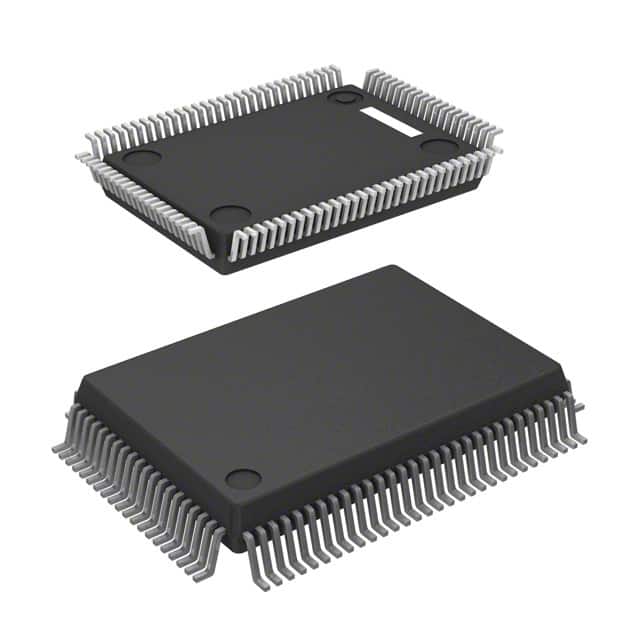
Infineon Technologies AT8992M-A2-T-1
- Part No.:
- AT8992M-A2-T-1
- Manufacturer:
- Infineon Technologies
- Category:
- Controllers
- Package:
- 100-BQFP
- Datasheet:
-
 AT8992M-A2-T-1.pdf
- Description:
- IC SWITCH PHY 100-MQFP
- Quantity:
- Payment:

- Shipping:

Inventory:4,932
Please send an inquiry. Send us your inquiry, and we will respond immediately.
Product details
Overview
AT8992M-A2-T-1 from Infineon Technologies is a 10/100 Mbps Ethernet physical layer transceiver (PHY) in 100-pin MQFP package, supporting IEEE 802.3u Fast Ethernet, MII/RMII interface, and integrated 1.25 V regulator. It operates from a single 3.3 V supply and features auto-negotiation, energy-detect mode, and 100BASE-TX compliance for embedded network edge applications.
For engineers reviewing the AT8992M-A2-T-1 datasheet, AT8992M-A2-T-1 pinout, AT8992M-A2-T-1 application, or AT8992M-A2-T-1 equivalent, key selection criteria include MII timing budget, RMII clock tolerance (±50 ppm), integrated voltage regulation capability, and 100BASE-TX PHY compliance status per IEEE 802.3u Clause 25.
Technical Context
The AT8992M-A2-T-1 implements a full-duplex 100BASE-TX PHY with integrated line driver/receiver, adaptive equalization, and baseline wander correction. It supports both MII (25 MHz reference clock) and RMII (50 MHz reference clock) host interfaces with configurable I/O voltage (3.3 V or 2.5 V).
Its internal 1.25 V regulator powers the core logic and analog front-end, eliminating need for external LDOs. Auto-MDIX and energy-detect power-down reduce system-level power consumption during link inactivity.
Key Specifications
| Parameter | Value and Actual Design Meaning |
|---|---|
| Data Rate | 10/100 Mbps - supports both 10BASE-T and 100BASE-TX modes per IEEE 802.3 standards. |
| Interface | MII/RMII - selectable host interface; RMII reduces pin count and simplifies PCB routing. |
| Supply Voltage | 3.3 V ±10% - single-supply operation eliminates dual-rail design complexity. |
| Integrated Regulator | 1.25 V output - powers internal analog/digital blocks, removing need for external 1.25 V LDO. |
| Auto-Negotiation | IEEE 802.3u compliant - negotiates speed/duplex with remote PHY without software intervention. |
| Energy Detect Mode | Low-power idle state - draws <150 µA when link partner is inactive, enabling green Ethernet operation. |
Pinout & Package
AT8992M-A2-T-1 is housed in a 100-pin plastic metric quad flat pack (MQFP) with 0.5 mm lead pitch, 14 mm × 20 mm body size, and exposed thermal pad for enhanced thermal dissipation in high-density industrial PCB layouts.
| Pin/Terminal | Circuit Role | Design Meaning |
|---|---|---|
| TXP/TXN | Differential 100BASE-TX transmit pair | Direct connection to magnetics; requires 100 Ω differential impedance trace routing. |
| RXP/RXN | Differential 100BASE-TX receive pair | Input to on-chip receiver with adaptive equalization; sensitive to board-level noise coupling. |
| REF_CLK | Reference clock input | 25 MHz for MII, 50 MHz for RMII; jitter tolerance ≤1.5 UI ensures reliable sampling. |
| CRS_DV | Carrier sense / data valid indicator | Synchronizes MII receive data capture; active high during valid frame reception. |
| MDIO/MDC | Management data I/O and clock | IEEE 802.3 clause 22 serial interface for register configuration and status readback. |
Key Features
| Feature | Design Value |
|---|---|
| Single 3.3 V supply operation | Eliminates need for auxiliary 2.5 V or 1.25 V rails, reducing BOM count and layout area. |
| Integrated 1.25 V regulator | Supplies internal analog/digital core; removes external LDO and associated decoupling components. |
| Auto-MDIX support | Automatically corrects crossover vs. straight-through cable connection, simplifying field deployment. |
| RMII interface option | Reduces host interface pin count from 16 (MII) to 7, easing microcontroller integration in space-constrained designs. |
Applications
| Industrial Ethernet Gateway | Smart Building Controller |
|---|---|
Use Scenario: Edge gateway aggregating Modbus TCP and EtherNet/IP traffic from PLCs and sensors. IC Role / Device Role / Timing Role: 100BASE-TX PHY bridging MCU's RMII interface to RJ-45 port with auto-negotiation and energy detect. Use Value: Single-supply operation and integrated 1.25 V regulator simplify power tree; RMII saves MCU GPIOs and PCB layers. | Use Scenario: HVAC controller connecting to building management system via managed switch infrastructure. IC Role / Device Role / Timing Role: MII-connected PHY providing IEEE 802.3u-compliant 100BASE-TX link with auto-MDIX and low-power idle. Use Value: Energy-detect mode cuts standby power by >90% versus always-on PHYs; auto-MDIX avoids field cabling errors. |
| POS Terminal Network Interface | Medical Device Data Logger |
Use Scenario: Payment terminal requiring secure, low-latency LAN connectivity for transaction upload. IC Role / Device Role / Timing Role: PHY handling 100BASE-TX physical layer signaling with deterministic MII timing and CRC offload support. Use Value: 25 MHz MII clock tolerance meets tight setup/hold margins of ARM Cortex-M7-based controllers. | Use Scenario: Portable diagnostic device transmitting ECG waveform data over hospital Ethernet backbone. IC Role / Device Role / Timing Role: RMII PHY enabling compact design with minimal MCU pin usage and low EMI emissions. Use Value: Exposed thermal pad ensures stable junction temperature under continuous 100 Mbps transmission at ambient up to 60°C. |
Equivalent & Alternatives
The following parts are listed as comparable options for similar 100BASE-TX PHY applications.
| Alternative Part | Technical Difference | Application Difference | Selection Advice |
|---|---|---|---|
| Microchip LAN8720AI-CP | 24-pin QFN, no integrated 1.25 V regulator; requires external 1.25 V supply. | Lacks energy-detect mode; higher idle current (~2 mA vs. <150 µA). | Preferred where board space is critical but power budget allows external regulator. |
| Realtek RTL8201CP-GR | 48-pin QFP, supports only MII; no RMII option or integrated regulator. | Requires separate 1.2 V core supply; no auto-MDIX hardware implementation. | Selected when legacy MII-only MCU interface and cost sensitivity outweigh feature trade-offs. |
Compared with LAN8720AI-CP and RTL8201CP-GR, AT8992M-A2-T-1 uniquely combines RMII support, integrated 1.25 V regulation, and energy-detect mode-enabling lower component count, smaller footprint, and sub-150 µA idle power in battery-backed or thermally constrained edge nodes.
Availability
AT8992M-A2-T-1 is available at Aetrix Electronics and suitable for industrial Ethernet gateways, smart building controllers, and medical data loggers requiring stable component supply, long-term lifecycle assurance, and traceable sourcing.
Supply support for AT8992M-A2-T-1 includes scheduled delivery planning, volume procurement assistance, BOM continuity management, traceable sourcing, and lifecycle availability coordination for OEM customers, industrial embedded developers, connected-device designers, and electronics production programs.
Manufacturer
Infineon Technologies is a German semiconductor manufacturer specializing in power management, automotive ICs, and industrial connectivity solutions, with global R&D and manufacturing infrastructure.
The AT8992M-A2-T-1 belongs to Infineon's Industrial Connectivity PHY product line, designed specifically for resource-constrained embedded systems needing robust, low-power, single-supply 100BASE-TX Ethernet physical layer interfacing.
FAQ
Does AT8992M-A2-T-1 support 1000BASE-T (Gigabit Ethernet)?
No. AT8992M-A2-T-1 is strictly a 10/100 Mbps PHY compliant with IEEE 802.3u (Fast Ethernet). It lacks the four-pair transceivers, DSP-based echo cancellation, and 125 MHz symbol rate required for 1000BASE-T. Its physical layer architecture is optimized for 100BASE-TX signaling only.
Can AT8992M-A2-T-1 operate with a 2.5 V I/O supply?
Yes. The I/O voltage is configurable via the VDDIO pin: tying it to 2.5 V enables 2.5 V-tolerant MII/RMII signaling, while 3.3 V enables standard 3.3 V I/O. Core logic remains powered by the internal 1.25 V regulator regardless of VDDIO setting.
Is an external crystal required for AT8992M-A2-T-1 operation?
No. AT8992M-A2-T-1 does not require an external crystal. It uses the host-provided REF_CLK (25 MHz for MII, 50 MHz for RMII) as its timing reference. No on-chip oscillator or crystal pins are present.
What is the thermal pad soldering requirement for the MQFP package?
The exposed thermal pad must be soldered to a dedicated PCB copper pour connected to ground plane via ≥4 thermal vias (0.3 mm diameter, spaced ≤2 mm apart). Insufficient thermal pad connection risks junction temperature exceeding 125°C under sustained 100 Mbps operation.
AT8992M-A2-T-1 Specifications
- Product attributes
- Attribute value
- Manufacturer:
- Infineon Technologies
- Package/Case:
- 100-BQFP
- Programmable:
- Not Verified
- Protocol:
- -
- Function:
- -
- Interface:
- -
- Standards:
- -
- Voltage - Supply:
- -
- Current - Supply:
- -
- Operating Temperature:
- -
- Supplier Device Package:
- PG-MQFP-100-2
- Grade:
- -
- Qualification:
- -
AT8992M-A2-T-1 FAQ
1.How can I place an order for AT8992M-A2-T-1 through Aetrix?
Please submit a Request for Quotation (RFQ) for AT8992M-A2-T-1 on Aetrix. Our sales agent will provide a competitive quotation and guide you through the order confirmation once you accept the terms.
2.Are the price and stock information for AT8992M-A2-T-1 reliable?
The price and inventory of AT8992M-A2-T-1 are updated periodically and may fluctuate due to market conditions. Stock and pricing data are typically refreshed every 24 hours. Quotation validity for AT8992M-A2-T-1 is usually 5 days.
3.What payment methods are accepted for AT8992M-A2-T-1?
We accept Wire Transfer, PayPal, Credit Card, Western Union, MoneyGram, and Escrow for AT8992M-A2-T-1 transactions.
Note: Certain payment methods may incur a processing fee.
4.How is shipping managed for AT8992M-A2-T-1?
AT8992M-A2-T-1 orders can be shipped via leading logistics carriers, including DHL, UPS, FedEx, TNT, or Registered Mail.
Once your AT8992M-A2-T-1 order is processed, you will receive an email with the shipment details and tracking number.
Note: Tracking information may take up to 24 hours to appear. Express delivery typically takes 3–5 business days.
5.How can I obtain technical support or documentation for AT8992M-A2-T-1?
For technical support, including AT8992M-A2-T-1 datasheets, pinout diagrams, or application guidance, please contact our engineering support team. They can provide detailed documentation and assistance for your AT8992M-A2-T-1 requirements.
6.How does Aetrix verify that AT8992M-A2-T-1 is sourced from the original manufacturer or authorized distributors?
All AT8992M-A2-T-1 products on Aetrix are procured from qualified distributors and authorized channels. Our dedicated quality assurance team conducts strict verification, including traceability checks and, if necessary, third-party testing. This ensures that AT8992M-A2-T-1 meets industry standards.
7.What is the process for return or replacement of AT8992M-A2-T-1?
All AT8992M-A2-T-1 units undergo pre-shipment inspection (PSI). If there is an issue with AT8992M-A2-T-1, returns or replacements are accepted under the following conditions:
1.Quantity discrepancies, incorrect items, or visible external defects (such as breakage or corrosion), acknowledged by Aetrix.
2.The issue is reported within 90 days of delivery.
3.The AT8992M-A2-T-1 part is unused and in its original packaging.
Return procedure for AT8992M-A2-T-1:
1.Submit a request within 90 days.
2.Obtain a Return Material Authorization (RMA) from Aetrix.
AT8992M-A2-T-1 Tags

-
PTN5150AHXMP
NXP USA Inc.

-
USB3740B-AI9-TR
Microchip Technology

-
USB3740B-AI2-TR
Microchip Technology

-
USB3300-EZK-TR
Microchip Technology
-
USB3300-EZK
Microchip Technology

-
FUSB340TMX
onsemi

-
FUSB302BMPX
onsemi

-
DP83826IRHBR
Texas Instruments

-
MCP2518FDT-E/QBB
Microchip Technology
-
FUSB302MPX
onsemi

-
MCP2518FDT-E/SL
Microchip Technology

-
FT260Q-R
FTDI, Future Technology Devices International Ltd
Tech Hub

An engineering guide to LED driver operation, constant-current and constant-voltage outputs, linear and switching topologies, dimming, IC selection, calculations, replacement compatibility, and fault c…

Operational amplifier guide covering op amp basics, feedback, ideal vs real op amps, common configurations, buffer circuits, offset, bias current, gain-bandwidth, slew rate, rail-to-rail limits and sel…

Jumper cables guide covering safe connection order, red and black clamp placement, final ground connection, cable gauge, length, clamp quality, copper vs CCA cables, jump starter comparison and battery…

LDO regulator guide covering low dropout voltage, power dissipation, thermal design, PSRR, output noise, capacitor stability, adjustable LDO circuits, LDO vs buck converter and datasheet selection chec…

Conditional Access Module guide covering CAM meaning, CI/CI+ interface, smart card authorization, DVB security workflow, TV and set-top box compatibility, internal electronics, ESD protection, connecto…

Guide to electronic component obsolescence covering EOL risk, PCN/PDN notices, last-time buy planning, replacement options, form-fit-function validation, counterfeit risk and BOM lifecycle management.

18650 battery guide covering lithium-ion cell basics, 3.6V/3.7V voltage, 4.2V charging, mAh and Wh capacity, protected cells, chargers, BMS, series-parallel packs, holders, welding and sourcing checks.…

Hall effect sensor guide covering working principle, linear and digital sensors, Arduino circuits, current sensing, speed detection, automotive applications, A3144 examples, signal filtering and datash…

Product Change Notification guide for electronic components, covering PCN meaning, PCN vs PDN/EOL, common change types, risk levels, form-fit-function review, engineering validation, BOM control, LTB/L…

A practical guide to blend door actuators, covering HVAC function, symptoms, location, AC and heater issues, reset and calibration, replacement cost, electrical diagnosis, compatibility checks, and rep…


