
 My Inquiry
 My Account


Microchip Technology ATF1508ASV-15AI100
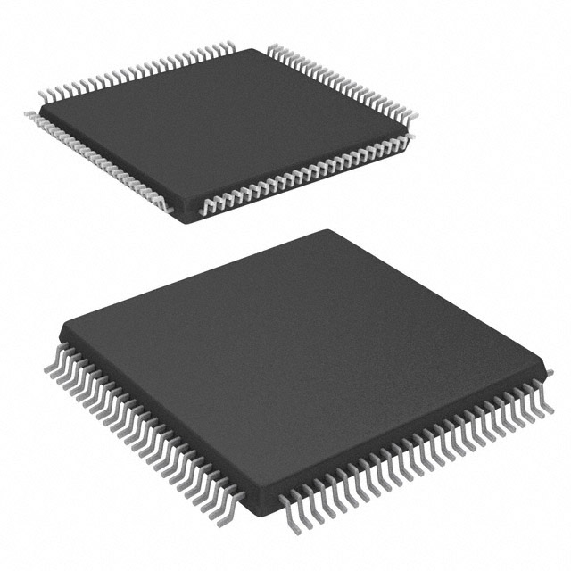
- Part No.:
- ATF1508ASV-15AI100
- Manufacturer:
- Microchip Technology
- Package:
- 100-TQFP
- Datasheet:
-
 ATF1508ASV-15AI100.pdf
- Description:
- IC CPLD 128MC 15NS 100TQFP
- Quantity:
- Payment:

- Shipping:

Inventory:4,345
Please send an inquiry. Send us your inquiry, and we will respond immediately.
Product details
Overview
ATF1508ASV-15AI100 from Microchip Technology (formerly Atmel) is a high-density, electrically-erasable Complex Programmable Logic Device (CPLD) with 128 macrocells, 15 ns maximum pin-to-pin delay, and operation across 3.0V–3.6V supply. It supports registered logic up to 77 MHz, features JTAG-based in-system programmability (ISP), and is packaged in a 100-lead TQFP for industrial temperature range (−40°C to +85°C). It serves as a reprogrammable glue logic replacement in legacy digital control systems.
For engineers reviewing the ATF1508ASV-15AI100 datasheet, ATF1508ASV-15AI100 pinout, ATF1508ASV-15AI100 application, or ATF1508ASV-15AI100 equivalent, key selection criteria include its 128-macrocell architecture, 3.3V-compatible I/O with programmable slew rate and open-collector option, IEEE 1149.1 boundary-scan support, PCI compliance, and dual power-down pins (PD1/PD2) enabling sub-5 mA standby current.
Technical Context
The ATF1508ASV-15AI100 implements a hierarchical CPLD architecture with eight logic chains, each supporting up to 40-product-term sum-of-products logic via cascade paths. Its global bus delivers 100+ signals-including all I/O, dedicated inputs, and buried macrocell feedback-to switch matrices that allocate up to 40 signals per logic block.
Each of its 128 macrocells integrates five product terms (expandable to 40 via cascade), configurable D/T/latch flip-flops, individual output enable routing, and programmable pin-keeper circuits. The device uses Atmel's advanced EEPROM technology for 10,000 program/erase cycles and 20-year data retention, with built-in security fuse and two bytes of user-accessible signature memory.
Key Specifications
| Parameter | Value and Actual Design Meaning |
|---|---|
| Logic Density | 128 macrocells - provides gate count equivalent to ~2,000 usable PLD gates for medium-complexity state machines and interface logic. |
| Propagation Delay | 15 ns max pin-to-pin - enables reliable operation in 66 MHz synchronous systems with margin. |
| Max Clock Frequency | 77 MHz registered operation - supports high-speed control loops and data path timing in industrial controllers. |
| I/O Count | Up to 96 bi-directional I/O + 4 dedicated inputs - allows full connectivity for parallel bus interfacing (e.g., ISA, LPC) without external glue logic. |
| Power Management | 5 µA standby (L-mode), 100 µA pin-controlled standby - reduces system idle power in battery-backed or energy-sensitive applications. |
| JTAG Compliance | IEEE Std. 1149.1-1990/1149.1a-1993 - enables production boundary-scan test, in-circuit debugging, and field firmware updates without physical rework. |
| Package & Temp | 100-lead TQFP, −40°C to +85°C - suitable for industrial motor drives, PLC modules, and telecom line cards requiring extended thermal reliability. |
Pinout & Package
ATF1508ASV-15AI100 is housed in a 100-lead Thin Quad Flat Package (TQFP) with 0.5 mm pitch, 14 mm × 14 mm body size, and exposed pad for thermal dissipation. Pin assignment follows standard Atmel CPLD layout with dedicated global clock (GCLK1–GCLK3), global clear (GCLR), output enable (OE1/OE2), power-down (PD1/PD2), and JTAG (TDI/TMS/TCK/TDO) pins.
| Pin/Terminal | Circuit Role | Design Meaning |
|---|---|---|
| 1, 41 | I/O/PD2 | Bi-directional I/O or power-down control input - when PD2 = high and power-down mode enabled, device enters sub-5 mA standby while latching outputs and internal states. |
| 3, 18, 34, 39, 51, 66, 82, 91 | VCCIO | I/O power supply pins - decoupled separately from VCCINT to support mixed-voltage signaling (e.g., 3.3V core / 5V I/O). |
| 4, 6, 15, 22, 62, 64, 73, 75, 85, 87, 89, 90 | I/O or dedicated function | Configurable I/O with programmable slew rate, open-collector option, and pin-keeper - eliminates need for external pull-ups on control lines like INT#, RESET#, or BUSY#. |
| 87, 85, 137 | I/O/GCLK3 | Third global clock input - enables multi-clock domain designs (e.g., separate control and data clocks) without external clock buffers. |
| 89, 87, 139 | INPUT/GCLK1 | Primary global clock input - routed directly to all macrocell registers with <5 ns skew, critical for synchronous state machine timing closure. |
| 91, 89, 141 | INPUT/GCLR | Asynchronous global reset - resets all macrocell flip-flops simultaneously, ensuring deterministic power-up initialization in safety-critical logic. |
Key Features
| Feature | Design Value |
|---|---|
| Programmable pin-keeper | Prevents floating inputs/I/Os without external resistors - reduces board area, BOM cost, and leakage-induced noise in unconnected control lines. |
| Three global clock inputs | Enables independent clock domains for control, data, and status logic - avoids clock domain crossing hazards in multi-function peripherals. |
| Input transition detection (ITD) | Detects edges on GCLKs, inputs, and I/Os without consuming macrocell resources - simplifies interrupt generation and event capture logic. |
| Combinatorial output with registered feedback | Allows buried latch within same macrocell - implements dual-edge-triggered logic or metastability-hardened synchronizers in minimal resource footprint. |
| VCC power-up reset | Guarantees register initialization at defined VCC threshold - ensures known startup state for finite-state machines in industrial automation hardware. |
Applications
| Industrial Motor Control | Legacy Bus Interface |
|---|---|
Use Scenario: Real-time PWM generation and fault monitoring in servo drive modules using discrete logic and microcontroller co-processing. IC Role / Device Role / Timing Role: CPLD implements synchronized 3-phase PWM edge alignment, overcurrent latch, and encoder quadrature decoding with sub-15 ns timing precision. Use Value: Replaces 8–10 discrete TTL/LSI chips, reduces PCB layer count by eliminating interconnect traces, and enables field-upgradable timing parameters via ISP. | Use Scenario: Bridging between modern ARM-based SoCs and legacy parallel buses (e.g., ISA, PC/104, or custom backplane interfaces). IC Role / Device Role / Timing Role: Glue logic handles address decoding, wait-state insertion, and bus arbitration with precise 15 ns setup/hold timing for 8/16-bit data transfers. Use Value: Eliminates need for ASIC or FPGA prototyping; supports drop-in replacement of obsolete PAL/GAL devices with identical pinout and JEDEC fuse map compatibility. |
| Telecom Line Card Control | Medical Instrumentation Sequencing |
Use Scenario: Supervisory logic for T1/E1 framer ICs, managing alarm reporting, loopback control, and channel provisioning in carrier-grade access equipment. IC Role / Device Role / Timing Role: Implements JTAG-accessible status registers, bit-banged SPI configuration, and fail-safe reset sequencing with ITD-based fault edge detection. Use Value: Enables remote diagnostics and firmware patching via existing JTAG infrastructure, reducing truck rolls and service downtime. | Use Scenario: Timing-critical sequencing of analog front-end calibration, ADC sampling, and DAC output in portable ultrasound or patient monitor subsystems. IC Role / Device Role / Timing Role: Generates synchronized strobes, manages sample-and-hold enable, and validates sensor readiness signals with deterministic 77 MHz register-to-output timing. Use Value: Meets IEC 62304 Class C software lifecycle requirements via hardware-enforced safe startup and watchdog-triggered recovery paths. |
Equivalent & Alternatives
The following parts are listed as comparable options for similar CPLD applications.
| Alternative Part | Technical Difference | Application Difference | Selection Advice |
|---|---|---|---|
| ATF1508ASVL-15AI100 | Same architecture and pinout, but includes automatic 5 µA standby mode (no PD pin required); lacks PD1/PD2 pins. | Better suited for always-on low-power systems where pin count is constrained and automatic sleep is preferred over manual control. | Select ATF1508ASVL-15AI100 if automatic ultra-low-power standby is required and PD pin flexibility is unnecessary. |
| XCR3256XL-10TQ144I | Xilinx CoolRunner-II CPLD with 256 macrocells, 10 ns delay, 3.3V-only I/O, no EEPROM (flash-based), different JTAG BSDL. | Higher density and speed, but requires flash programming infrastructure and lacks EEPROM reprogrammability in deployed units. | Select XCR3256XL-10TQ144I only when >128 macrocells are needed and field reprogramming via JTAG is not required. |
Compared with ATF1508ASVL-15AI100, the ATF1508ASV-15AI100 trades automatic standby for explicit PD pin control-enabling conditional power gating in response to system events. Against XCR3256XL-10TQ144I, it offers superior field-upgradability and pin-compatible migration from legacy Atmel designs, at the cost of lower macrocell count and slightly higher propagation delay.
Availability
ATF1508ASV-15AI100 is available at Aetrix Electronics and suitable for industrial motor control, legacy bus interface, and telecom line card applications requiring stable component supply, long-life availability, and reprogrammable logic for design iteration and field updates.
Supply support for ATF1508ASV-15AI100 includes scheduled delivery planning, volume procurement assistance, BOM continuity management, traceable sourcing, and lifecycle availability coordination for OEM customers, industrial embedded developers, connected-device designers, and electronics production programs.
Manufacturer
Microchip Technology acquired Atmel in 2016 and maintains full support for the ATF1508ASV family, including datasheets, BSDL models, and legacy programming tools.
The ATF1508ASV series was designed as a high-reliability, EEPROM-based CPLD solution for industrial and telecom applications requiring in-system programmability, long-term data retention, and robust boundary-scan testability.
FAQ
What is the maximum operating frequency of the ATF1508ASV-15AI100?
The ATF1508ASV-15AI100 supports registered logic operation up to 77 MHz, with a minimum global clock period of 13 ns (fCNT = 76.9 MHz) and array clock frequency up to 58.8 MHz. These values are guaranteed under industrial temperature conditions (−40°C to +85°C) and 3.3V supply. The ATF1508ASV-15AI100 achieves this performance using optimized routing and low-skew global clock distribution across its 128-macrocell array.
Does the ATF1508ASV-15AI100 support in-system programming (ISP)?
Yes, the ATF1508ASV-15AI100 fully supports IEEE 1149.1-compliant in-system programming via its four-pin JTAG interface (TDI, TMS, TCK, TDO). Programming can be performed without removing the device from the PCB using Atmel-provided or third-party ISP tools. The ATF1508ASV-15AI100 also allows disabling JTAG to reclaim all four pins as general-purpose I/O when ISP is not required.
What power management modes does the ATF1508ASV-15AI100 offer?
The ATF1508ASV-15AI100 provides three distinct low-power modes: automatic 5 µA standby (L-version behavior), pin-controlled 100 µA standby using PD1/PD2, and optional macrocell-level reduced-power mode adding tRPA delay. In power-down mode, supply current drops below 5 mA while latching all outputs and internal states. The ATF1508ASV-15AI100 retains full functionality upon wake-up with no configuration reload required.
Can the ATF1508ASV-15AI100 replace older PAL/GAL devices?
Yes, the ATF1508ASV-15AI100 is widely used as a drop-in replacement for obsolete 22V10, 20RA10, and GAL22V10 devices due to its JEDEC-standard fuse map compatibility, identical 100-lead TQFP footprint, and support for legacy design tools. Its 128 macrocells and enhanced routing provide backward compatibility while enabling feature upgrades such as JTAG test access and field reprogramming - all without modifying the ATF1508ASV-15AI100 PCB layout.
What is the purpose of the Input Transition Detection (ITD) feature in the ATF1508ASV-15AI100?
The Input Transition Detection (ITD) circuitry in the ATF1508ASV-15AI100 monitors edges on global clocks, inputs, and I/O pins independently of macrocell usage - enabling efficient asynchronous event capture (e.g., interrupt assertion, button press, or fault signal) without consuming logic resources. This feature is especially valuable in the ATF1508ASV-15AI100 for implementing low-latency response paths in safety-critical or real-time control applications.
ATF1508ASV-15AI100 Specifications
- Product attributes
- Attribute value
- Manufacturer:
- Microchip Technology
- Series:
- ATF15xx
- Package/Case:
- 100-TQFP
- Packaging:
- Tray
- Product Status:
- Obsolete
- Programmable:
- Not Verified
- Programmable Type:
- In System Programmable (min 10K program/erase cycles)
- Delay Time tpd(1) Max:
- 15 ns
- Voltage Supply - Internal:
- 3V ~ 3.6V
- Number of Logic Elements/Blocks:
- -
- Number of Macrocells:
- 128
- Number of Gates:
- -
- Number of I/O:
- 80
- Operating Temperature:
- -40°C ~ 85°C (TA)
- Grade:
- -
- Qualification:
- -
- Mounting Type:
- Surface Mount
- Supplier Device Package:
- 100-TQFP (14x14)
ATF1508ASV-15AI100 FAQ
1.How can I place an order for ATF1508ASV-15AI100 through Aetrix?
Please submit a Request for Quotation (RFQ) for ATF1508ASV-15AI100 on Aetrix. Our sales agent will provide a competitive quotation and guide you through the order confirmation once you accept the terms.
2.Are the price and stock information for ATF1508ASV-15AI100 reliable?
The price and inventory of ATF1508ASV-15AI100 are updated periodically and may fluctuate due to market conditions. Stock and pricing data are typically refreshed every 24 hours. Quotation validity for ATF1508ASV-15AI100 is usually 5 days.
3.What payment methods are accepted for ATF1508ASV-15AI100?
We accept Wire Transfer, PayPal, Credit Card, Western Union, MoneyGram, and Escrow for ATF1508ASV-15AI100 transactions.
Note: Certain payment methods may incur a processing fee.
4.How is shipping managed for ATF1508ASV-15AI100?
ATF1508ASV-15AI100 orders can be shipped via leading logistics carriers, including DHL, UPS, FedEx, TNT, or Registered Mail.
Once your ATF1508ASV-15AI100 order is processed, you will receive an email with the shipment details and tracking number.
Note: Tracking information may take up to 24 hours to appear. Express delivery typically takes 3–5 business days.
5.How can I obtain technical support or documentation for ATF1508ASV-15AI100?
For technical support, including ATF1508ASV-15AI100 datasheets, pinout diagrams, or application guidance, please contact our engineering support team. They can provide detailed documentation and assistance for your ATF1508ASV-15AI100 requirements.
6.How does Aetrix verify that ATF1508ASV-15AI100 is sourced from the original manufacturer or authorized distributors?
All ATF1508ASV-15AI100 products on Aetrix are procured from qualified distributors and authorized channels. Our dedicated quality assurance team conducts strict verification, including traceability checks and, if necessary, third-party testing. This ensures that ATF1508ASV-15AI100 meets industry standards.
7.What is the process for return or replacement of ATF1508ASV-15AI100?
All ATF1508ASV-15AI100 units undergo pre-shipment inspection (PSI). If there is an issue with ATF1508ASV-15AI100, returns or replacements are accepted under the following conditions:
1.Quantity discrepancies, incorrect items, or visible external defects (such as breakage or corrosion), acknowledged by Aetrix.
2.The issue is reported within 90 days of delivery.
3.The ATF1508ASV-15AI100 part is unused and in its original packaging.
Return procedure for ATF1508ASV-15AI100:
1.Submit a request within 90 days.
2.Obtain a Return Material Authorization (RMA) from Aetrix.
ATF1508ASV-15AI100 Tags
-
5M40ZE64C5N
Intel
-
ATF1502ASV-15AU44
Microchip Technology
-
5M80ZE64C5N
Intel
-
5M80ZT100C5N
Intel
-
ATF1502AS-10AU44
Microchip Technology
-
ATF1502AS-10JU44
Microchip Technology
-
5M80ZE64I5N
Intel
-
5M80ZT100I5N
Intel
-
LC4032V-75TN48C
Lattice Semiconductor Corporation
-
ATF1504ASV-15AU44
Microchip Technology
-
ATF1504AS-10JU44
Microchip Technology
-
5M160ZE64C5N
Intel
Tech Hub

TTL and CMOS logic families differ in thresholds, loading, output drive, power and timing. This engineering guide compares 74HC and 74HCT, calculates noise margins and checks 3.3 V/5 V compatibility.

A practical engineering guide to 3.3V and 5V logic compatibility, input thresholds, resistor dividers, translator ICs, MOSFET level shifting, I2C pull-ups, timing limits and power-sequencing risks.

The 74HC595 uses push-pull logic outputs, while the TPIC6B595 uses 50 V open-drain DMOS sinks for higher-power loads. This guide compares timing, current limits, 3.3 V interfacing, load wiring, thermal…

The 74HC595 converts serial data into eight stable parallel outputs. This guide covers pin functions, shift and storage timing, OE and MR behavior, drive-current limits, cascading, voltage compatibilit…

A technical comparison of level-sensitive latches and edge-triggered flip-flops, covering timing windows, setup and hold limits, master–slave operation, time borrowing, race-through, HDL inference and…

A D latch stores one bit while Enable controls when data can pass. This reference covers gate-level operation, truth tables, transparency, setup and hold timing, LE versus OE, common ICs and practical …

An SR latch stores one bit through cross-coupled feedback. This engineering reference covers NOR and NAND implementations, truth tables, forbidden-state recovery, gated operation, switch debouncing, fa…

Latch circuits retain one bit through feedback. This technical reference covers SR and D latches, truth tables, transparency, timing limits, latch-versus-flip-flop behavior, applications and common log…

An engineering guide to LED driver operation, constant-current and constant-voltage outputs, linear and switching topologies, dimming, IC selection, calculations, replacement compatibility, and fault c…

Operational amplifier guide covering op amp basics, feedback, ideal vs real op amps, common configurations, buffer circuits, offset, bias current, gain-bandwidth, slew rate, rail-to-rail limits and sel…


