
 My Inquiry
 My Account


Microchip Technology ATMSL3085BT
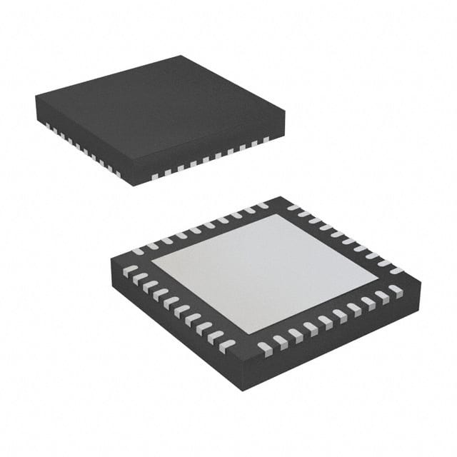
- Part No.:
- ATMSL3085BT
- Manufacturer:
- Microchip Technology
- Category:
- LED Drivers
- Package:
- 40-WFQFN Exposed Pad
- Datasheet:
-
 ATMSL3085BT.pdf
- Description:
- IC LED DRIVER CTRLR PWM 40TQFN
- Quantity:
- Payment:

- Shipping:

Inventory:1,601
Please send an inquiry. Send us your inquiry, and we will respond immediately.
Product details
Overview
ATMSL3085BT from Microchip Technology (formerly Atmel) is an 8-string white/RGB LED driver IC using external MOSFETs to sink up to 350mA per string with ±1.5% current accuracy and matching, adaptive DC-DC power supply control via two efficiency optimizer outputs, and I²C/SMBus interface at 1MHz for frame-synchronized area dimming in LCD TV backlight systems.
For engineers reviewing the ATMSL3085BT datasheet, ATMSL3085BT pinout, ATMSL3085BT application, or ATMSL3085BT equivalent, this device supports real-time video-sync PWM phasing, EEPROM-configurable power-up defaults, open/short-circuit fault detection per string, and multi-device chain negotiation of optimal LED supply voltage - critical for high-dynamic-range backlight design.
Technical Context
The ATMSL3085BT implements a dual-efficiency-optimizer architecture with FBO1/FBO2 outputs and FBI1 input, enabling up to eight devices to cascade and negotiate minimum required LED supply voltage while maintaining current regulation across all strings. It uses external MOSFETs (gate drive charge ≤10nC) and source-sense resistors (500mV threshold) for precise per-string current setting.
Its PWM engine synchronizes to external video timing via PHI (100Hz–480Hz) and GSC inputs, supporting 12-bit per-string intensity control (PWMn registers), 8-bit global scaling (GINT/ALTGINT), and programmable phase shifting to reduce motion blur and input capacitor stress. Internal VDD (2.5V) and VCC (5V) LDOs are powered from 12V VIN.
Key Specifications
| Parameter | Value and Actual Design Meaning |
|---|---|
| LED strings | 8 parallel strings, each driven by external N-channel MOSFETs with source-sense feedback |
| Max per-string current | 350mA, set by external sense resistor (500mV full-scale) |
| Current accuracy & matching | ±1.5% over –40°C to +105°C, enabling consistent white point and color gamut |
| I²C interface speed | 1MHz maximum, supporting up to eight devices on one bus with broadcast write capability |
| PWM resolution | 12-bit per string (PWMn registers), 8-bit global scaling (GINT/ALTGINT), synchronized to video frame timing |
| Efficiency optimizers | Two FBO outputs (FBO1/FBO2) and one FBI1 input for daisy-chained supply voltage negotiation |
| Operating temperature | –40°C to +105°C ambient, with thermal shutdown protection |
| Package | 40-pin TQFN, 6mm × 6mm × 0.75mm, exposed pad for thermal management |
Pinout & Package
ATMSL3085BT is housed in a 40-pin, 6mm × 6mm × 0.75mm TQFN package with exposed thermal pad (EP). Pin functions follow non-sequential naming (0, 2, 4, 6, 9, 11, 12, 14) to ensure register compatibility with the MSL2161 16-string variant.
| Pin/Terminal | Circuit Role | Design Meaning |
|---|---|---|
| G0, G2, G4, G6, G9, G11, G12, G14 | Gate drive outputs | Drive gates of external N-MOSFETs; each rated for ≤10nC gate charge, optimized for fast switching |
| S0, S2, S4, S6, S9, S11, S12, S14 | Source sense inputs | Connect to MOSFET source and current-sense resistor; regulate string current at 500mV threshold |
| D0, D2, D4, D6, D9, D11, D12, D14 | Drain sense inputs | Monitor drain voltage via 10MΩ resistor to detect open/short faults (threshold: 8V) |
| FBO1, FBO2 | Efficiency optimizer outputs | Inject 0–360µA into external DC-DC feedback node to dynamically minimize LED supply voltage |
| FBI1 | Efficiency optimizer input | Accepts FBO1 output from upstream device in daisy-chain; enables multi-device supply negotiation |
| FLTB | Fault indication output | Active-low open-drain signal asserting on open/short/over-temp/loss-of-sync; latched until fault registers read |
| PHI, GSC, PWM | Video synchronization inputs | PHI (frame sync, 100Hz–480Hz), GSC (pixel clock, 0–10MHz), PWM (external brightness control, ≤5kHz) |
| SDA, SCL, ADDR | I²C interface | Standard 1MHz I²C bus with hardware slave address selection via ADDR resistor to GND |
Key Features
| Feature | Design Value |
|---|---|
| Adaptive SourcePower™ technology | Two FBO outputs and FBI1 input enable up to eight ATMSL3085BT devices to auto-negotiate minimum LED supply voltage, reducing power loss without compromising current accuracy |
| 12-bit per-string PWM dimming | Enables precise area dimming for dynamic contrast enhancement in LCD TVs and medical displays, with phase-shifted timing to suppress motion blur |
| EEPROM-configurable defaults | On-chip EEPROM stores power-up register values (e.g., ISTR, PWMn, STRnSET), eliminating boot-time MCU configuration overhead |
| Comprehensive fault monitoring | Detects per-string open/short circuits, loss-of-sync, and over-temperature; FLTB asserts low and status is readable via I²C fault registers |
| Video-sync PWM engine | Accepts PHI (VSYNC) and GSC (HSYNC) inputs to align LED off-times with LCD pixel update, minimizing waterfall noise and improving perceived image quality |
| External MOSFET architecture | Decouples high-voltage/high-current handling from IC die, enabling flexible LED string voltage (e.g., 35–38V for 10× white LEDs) and scalable thermal design |
Applications
| Television Backlighting | Medical Instrument Displays |
|---|---|
Use Scenario: High-dynamic-range (HDR) LCD TV backlight with local dimming zones. IC Role / Device Role / Timing Role: ATMSL3085BT drives eight LED strings per zone, synchronizing PWM off-times to LCD refresh via PHI/GSC to eliminate motion artifacts. Use Value: Achieves >100,000:1 contrast ratio and reduces motion blur by aligning LED dimming with pixel update timing. | Use Scenario: Brightness-stable, flicker-free display backlight in surgical monitors and diagnostic imaging equipment. IC Role / Device Role / Timing Role: ATMSL3085BT provides ±1.5% current matching across strings and EEPROM-retained calibration to maintain consistent luminance and white point over time and temperature. Use Value: Ensures accurate grayscale rendering and eliminates visual fatigue during prolonged clinical use. |
| Automotive Infotainment | Architectural Lighting Control |
Use Scenario: A/V display backlight in automotive head units operating across –40°C to +105°C ambient. IC Role / Device Role / Timing Role: ATMSL3085BT manages thermal derating and fault reporting (open/short/over-temp) via FLTB and I²C, with EN-controlled cold-start bootload from EEPROM. Use Value: Guarantees fail-safe operation and meets AEC-Q100 reliability requirements without external supervision logic. | Use Scenario: Programmable RGB backlight for signage and façade lighting with smooth color transitions. IC Role / Device Role / Timing Role: ATMSL3085BT drives white + RGB strings independently using 12-bit PWMn registers and global 8-bit intensity scaling for hue/saturation/brightness control. Use Value: Enables precise color mixing and gamma-corrected dimming curves without MCU-intensive real-time computation. |
Equivalent & Alternatives
The following parts are listed as comparable options for similar 8-string LED driver applications.
| Alternative Part | Technical Difference | Application Difference | Selection Advice |
|---|---|---|---|
| TI TLC6983RGER | 16-channel constant-current LED driver with integrated MOSFETs; no external FET support; 40V max output; no efficiency optimizer outputs | Best suited for lower-current (<120mA), fixed-voltage LED arrays where board space is constrained and external MOSFETs are undesirable | Select TLC6983RGER when integrated drivers simplify layout and supply voltage is stable; choose ATMSL3085BT when higher current, adaptive supply control, or thermal scalability is required |
| ON Semiconductor NCP5623DTBR2G | 3-channel I²C LED driver with integrated MOSFETs; max 95mA/channel; no video sync inputs; no fault detection beyond thermal shutdown | Targeted at portable displays and indicator lighting where cost and footprint are primary; lacks area dimming or fault granularity | Select NCP5623DTBR2G for low-cost, low-power UI lighting; ATMSL3085BT remains preferred for industrial-grade backlighting with video synchronization and per-string diagnostics |
Compared with TLC6983RGER and NCP5623DTBR2G, the ATMSL3085BT uniquely combines external MOSFET flexibility, adaptive power optimization, video-sync PWM phasing, and per-string fault visibility - making it the only option among the three capable of driving 350mA strings while negotiating supply voltage across multiple devices in HDR TV backlight systems.
Availability
ATMSL3085BT is available at Aetrix Electronics and suitable for television backlighting, medical instrumentation displays, automotive infotainment systems, architectural lighting, and channel signage requiring stable component supply, long-term lifecycle support, and traceable sourcing.
Supply support for ATMSL3085BT includes scheduled delivery planning, volume procurement assistance, BOM continuity management, traceable sourcing, and lifecycle availability coordination for OEM customers, industrial embedded developers, connected-device designers, and electronics production programs.
Manufacturer
Microchip Technology acquired Atmel in 2016 and maintains its high-performance analog and mixed-signal product lines, including LED drivers engineered for reliability in demanding industrial and automotive environments.
The ATMSL3085BT belongs to Microchip's Adaptive SourcePower™ LED driver family, designed specifically for high-efficiency, video-synchronized local dimming in large-area LCD backlights where thermal management, current precision, and system-level power optimization are critical.
FAQ
What is the maximum LED string current supported by the ATMSL3085BT?
The ATMSL3085BT supports up to 350mA per LED string, set by an external current-sense resistor connected to the source terminal of each external N-channel MOSFET. The internal regulation threshold is fixed at 500mV, so RS = 500mV / ILED. For example, a 350mA string requires RS ≈ 1.43Ω. Current is digitally trimmed via the 8-bit ISTR register (0x31), allowing fine-grained reduction from full scale without changing hardware.
How does the ATMSL3085BT achieve adaptive power control across multiple devices?
The ATMSL3085BT uses two efficiency optimizer outputs (FBO1 and FBO2) and one input (FBI1) to form a daisy chain. When FBI1 of Device N is connected to FBO1 of Device N−1, up to eight ATMSL3085BT devices automatically negotiate the minimum LED supply voltage required to maintain current regulation across all strings. Each FBO injects 0–360µA into the external DC-DC feedback node, dynamically lowering the supply until the highest-Vf string reaches regulation margin.
Can the ATMSL3085BT synchronize LED PWM timing to video signals?
Yes, the ATMSL3085BT accepts external synchronization via PHI (frame sync, typically VSYNC) and GSC (gate shift clock, typically HSYNC) inputs. The internal PWM engine locks to PHI frequency (100Hz–480Hz) and uses GSC to define 12-bit on-time counts per string. This enables precise alignment of LED off-times with LCD pixel updates, reducing motion blur and waterfall noise - a key requirement for ATMSL3085BT in high-end television backlight designs.
What fault conditions does the ATMSL3085BT monitor, and how are they reported?
The ATMSL3085BT monitors open-circuit and short-circuit faults per LED string (using Dn pins), loss-of-sync on PHI/GSC inputs, and over-temperature conditions. All faults assert the open-drain FLTB pin low and populate dedicated I²C fault registers (0x00–0x02). Fault status is latched until read, and FLTB remains low until cleared - enabling robust MCU-based error handling without polling overhead in the ATMSL3085BT system.
Does the ATMSL3085BT require external components for power sequencing or startup?
No external sequencing components are required. The ATMSL3085BT integrates 2.5V (VDD) and 5V (VCC) LDO regulators powered from 12V VIN. Bypass capacitors (4.7µF ceramic on VDD/VCC, 10µF on VIN) are mandatory and must be placed close to respective pins. Startup is controlled by the EN pin: driving EN high loads EEPROM defaults into registers and clears fault flags, simulating a cold start - simplifying ATMSL3085BT integration in systems with minimal MCU boot-time intervention.
ATMSL3085BT Specifications
- Product attributes
- Attribute value
- Manufacturer:
- Microchip Technology
- Series:
- -
- Package/Case:
- 40-WFQFN Exposed Pad
- Packaging:
- Tape & Reel (TR)
- Product Status:
- Active
- Type:
- DC DC Controller
- Topology:
- Step-Up (Boost)
- Internal Switch(s):
- No
- Number of Outputs:
- 8
- Voltage - Supply (Min):
- 10.8V
- Voltage - Supply (Max):
- 13.2V
- Voltage - Output:
- -
- Current - Output / Channel:
- -
- Frequency:
- -
- Dimming:
- PWM
- Applications:
- Backlight, Lighting
- Operating Temperature:
- -40°C ~ 105°C (TA)
- Grade:
- -
- Qualification:
- -
- Mounting Type:
- Surface Mount
- Supplier Device Package:
- 40-TQFN (6x6)
ATMSL3085BT FAQ
1.How can I place an order for ATMSL3085BT through Aetrix?
Please submit a Request for Quotation (RFQ) for ATMSL3085BT on Aetrix. Our sales agent will provide a competitive quotation and guide you through the order confirmation once you accept the terms.
2.Are the price and stock information for ATMSL3085BT reliable?
The price and inventory of ATMSL3085BT are updated periodically and may fluctuate due to market conditions. Stock and pricing data are typically refreshed every 24 hours. Quotation validity for ATMSL3085BT is usually 5 days.
3.What payment methods are accepted for ATMSL3085BT?
We accept Wire Transfer, PayPal, Credit Card, Western Union, MoneyGram, and Escrow for ATMSL3085BT transactions.
Note: Certain payment methods may incur a processing fee.
4.How is shipping managed for ATMSL3085BT?
ATMSL3085BT orders can be shipped via leading logistics carriers, including DHL, UPS, FedEx, TNT, or Registered Mail.
Once your ATMSL3085BT order is processed, you will receive an email with the shipment details and tracking number.
Note: Tracking information may take up to 24 hours to appear. Express delivery typically takes 3–5 business days.
5.How can I obtain technical support or documentation for ATMSL3085BT?
For technical support, including ATMSL3085BT datasheets, pinout diagrams, or application guidance, please contact our engineering support team. They can provide detailed documentation and assistance for your ATMSL3085BT requirements.
6.How does Aetrix verify that ATMSL3085BT is sourced from the original manufacturer or authorized distributors?
All ATMSL3085BT products on Aetrix are procured from qualified distributors and authorized channels. Our dedicated quality assurance team conducts strict verification, including traceability checks and, if necessary, third-party testing. This ensures that ATMSL3085BT meets industry standards.
7.What is the process for return or replacement of ATMSL3085BT?
All ATMSL3085BT units undergo pre-shipment inspection (PSI). If there is an issue with ATMSL3085BT, returns or replacements are accepted under the following conditions:
1.Quantity discrepancies, incorrect items, or visible external defects (such as breakage or corrosion), acknowledged by Aetrix.
2.The issue is reported within 90 days of delivery.
3.The ATMSL3085BT part is unused and in its original packaging.
Return procedure for ATMSL3085BT:
1.Submit a request within 90 days.
2.Obtain a Return Material Authorization (RMA) from Aetrix.
ATMSL3085BT Tags

-
BCR402RE6327HTSA1
Infineon Technologies

-
BCR430UXTSA2
Infineon Technologies

-
BCR420UE6433HTMA1
Infineon Technologies
-
BCR420UE6327HTSA1
Infineon Technologies
-
BCR421UE6327HTSA1
Infineon Technologies

-
LYT1604D-TL
Power Integrations

-
HV9910CLG-G
Microchip Technology

-
CL2N8-G
Microchip Technology

-
BCR420UW6-7
Diodes Incorporated
-
BCR421UW6-7
Diodes Incorporated

-
BCR420UFD-7
Diodes Incorporated
-
BCR421UFD-7
Diodes Incorporated
Tech Hub

TTL and CMOS logic families differ in thresholds, loading, output drive, power and timing. This engineering guide compares 74HC and 74HCT, calculates noise margins and checks 3.3 V/5 V compatibility.

A practical engineering guide to 3.3V and 5V logic compatibility, input thresholds, resistor dividers, translator ICs, MOSFET level shifting, I2C pull-ups, timing limits and power-sequencing risks.

The 74HC595 uses push-pull logic outputs, while the TPIC6B595 uses 50 V open-drain DMOS sinks for higher-power loads. This guide compares timing, current limits, 3.3 V interfacing, load wiring, thermal…

The 74HC595 converts serial data into eight stable parallel outputs. This guide covers pin functions, shift and storage timing, OE and MR behavior, drive-current limits, cascading, voltage compatibilit…

A technical comparison of level-sensitive latches and edge-triggered flip-flops, covering timing windows, setup and hold limits, master–slave operation, time borrowing, race-through, HDL inference and…

A D latch stores one bit while Enable controls when data can pass. This reference covers gate-level operation, truth tables, transparency, setup and hold timing, LE versus OE, common ICs and practical …

An SR latch stores one bit through cross-coupled feedback. This engineering reference covers NOR and NAND implementations, truth tables, forbidden-state recovery, gated operation, switch debouncing, fa…

Latch circuits retain one bit through feedback. This technical reference covers SR and D latches, truth tables, transparency, timing limits, latch-versus-flip-flop behavior, applications and common log…

An engineering guide to LED driver operation, constant-current and constant-voltage outputs, linear and switching topologies, dimming, IC selection, calculations, replacement compatibility, and fault c…

Operational amplifier guide covering op amp basics, feedback, ideal vs real op amps, common configurations, buffer circuits, offset, bias current, gain-bandwidth, slew rate, rail-to-rail limits and sel…


